76 Worked Examples: Propulsion Systems
These worked examples have been fielded as homework problems or exam questions.
Worked Example #1
A static thrust stand is to be designed to test jet engines. The following conditions are expected for a typical test: intake air velocity = 200 m/s, exhaust gas velocity = 500 m/s, intake cross-section area = 1 m , static intake pressure = 78.5 kPa, static intake temperature = 268K, static exhaust pressure = 101 kPa. Estimate the thrust reaction force to design the test stand to withstand, if it must have a structural safety factor of 3.
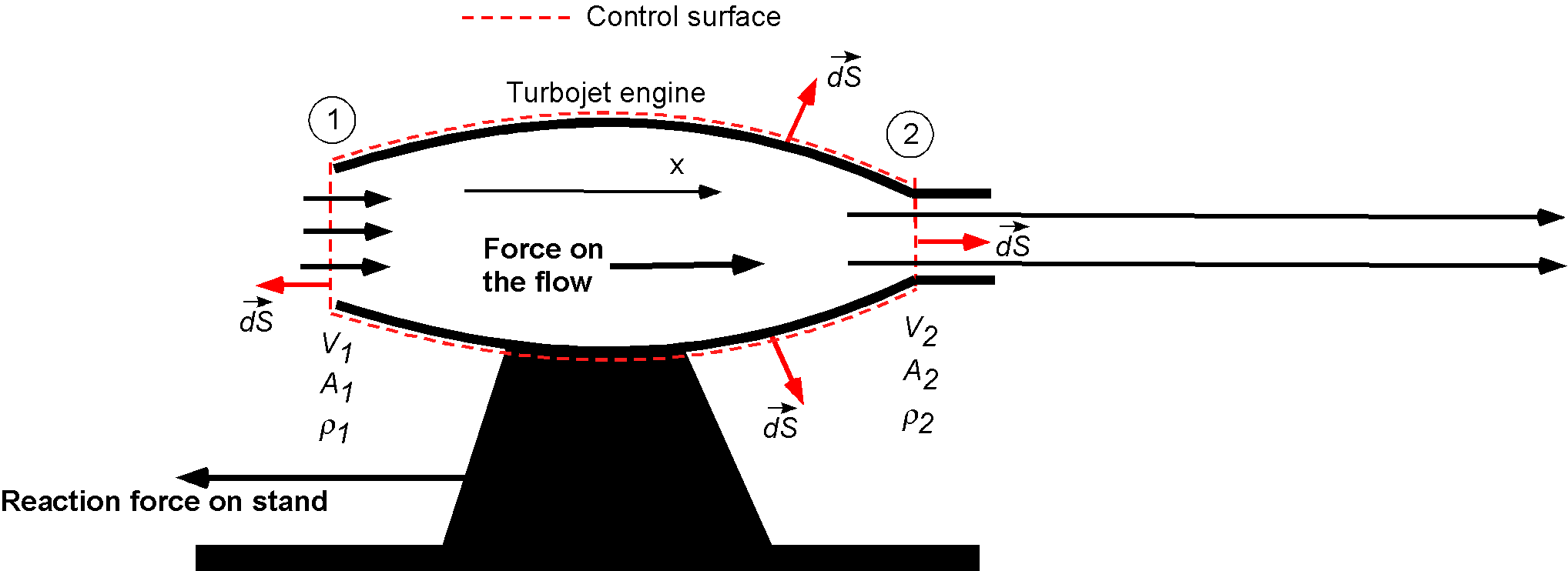
Assume that the inlet condition is identified as station 1 and the outlet as station 2. Assume also that the exit area is equal to the inlet area. The density of the air at the inlet can be found using
![\[ \varrho_1 = \frac{p_1}{R T_1} = \frac{78.5 \times 10^3}{(287)(268)} = 1.0206~\mbox{kg m${^{-3}}$} \]](https://eaglepubs.erau.edu/app/uploads/quicklatex/quicklatex.com-b0ba9cd0131c2309a58a9b3aa5bfcf43_l3.svg "Rendered by QuickLaTeX.com")
From continuity considerations (assume 1-dimensional, steady flow), then
![\[ \varrho_1 A_1 V_1 = \varrho_2 A_2 V_2 = \overbigdot{m} = 204.12~\mbox{kg s$^{-1}$} \]](https://eaglepubs.erau.edu/app/uploads/quicklatex/quicklatex.com-a07a728270a2591642a184a344180931_l3.svg "Rendered by QuickLaTeX.com")
Conservation of momentum (assume 1-dimensional flow) gives the force on the fluid as
![\[ F = -p_1 A_1 + p_2 A_2 + \overbigdot{m} ( V_2 - V_1 ) \]](https://eaglepubs.erau.edu/app/uploads/quicklatex/quicklatex.com-d8f2ebdc40c4269ff94d0ab464645781_l3.svg "Rendered by QuickLaTeX.com")
and substituting the numerical values gives
![\[ F = (-78.5 \times 10^3)(1.0) + (101.0 \times 10^3) \times 1.0 + 204.12 \times (500.0 - 200.0) = 83,736~\mbox{N} \]](https://eaglepubs.erau.edu/app/uploads/quicklatex/quicklatex.com-f040a562ac62b77cd6e8e1fb7b713785_l3.svg "Rendered by QuickLaTeX.com")
For the conditions stated, the residual force on the fluid must be 83,736 N in the direction of fluid flow, and the reaction force on the test stand will be in the opposite direction. Because there is a structural factor of safety requirement of 3, the force to which the stand should be designed is about 251 kN.
Worked Example #2
Consider a turbojet-powered airplane flying at an altitude of 35,000 ft with a true airspeed  of 530 mph; refer to the schematic below. At this altitude, the pressure ratio
  is 0.2353, and the density ratio
  is 0.3099. The inlet and exit areas of the turbojet engine are
  =13 ft and
  = 8 ft, respectively. The fuel-to-air ratio by mass injected into the engine is 0.005. The jet exit velocity
  is 1,510 ft s
 and the pressure at the exit
  is 450.0 lb ft
 . Assume one-dimensional flow.
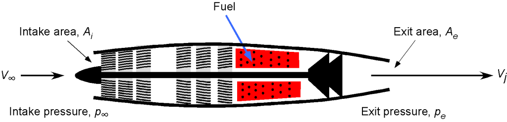
- Draw an appropriately annotated control volume to analyze this problem.
- Calculate the mass flow rate of air at the inlet to the turbojet.
- Calculate the thrust of the turbojet at this flight condition.
- Calculate the fuel consumption of the turbojet in units of lb hr.
- Determine the turbojet’s thrust-specific fuel consumption (TSFC).
1. The control volume is shown in the figure below.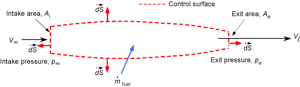
2. The air density at the given altitude is
![\[ \varrho_\infty = \sigma \, \varrho_0 = 0.3099 \times 0.002378 = 0.000737~\mbox{slug ft${^{-3}}$} \]](https://eaglepubs.erau.edu/app/uploads/quicklatex/quicklatex.com-1636fdf130cae4bcc553deec4ba715b4_l3.svg "Rendered by QuickLaTeX.com")
The corresponding ambient pressure of the air is
![\[ p_\infty = \delta \, p_0 = 0.2353 \times 2116.4 = 498.0~\mbox{lb ft$^{-2}$} \]](https://eaglepubs.erau.edu/app/uploads/quicklatex/quicklatex.com-f526a408ae9a4c51be8e815333cc9f81_l3.svg "Rendered by QuickLaTeX.com")
3. The air mass flow rate at the inlet of the turbojet engine is
![\[ \overbigdot{m}_{\rm air} = \varrho_{\infty} \, A_i \, V_\infty \]](https://eaglepubs.erau.edu/app/uploads/quicklatex/quicklatex.com-6b55c6b2ee9bee12a6adc5aa8c5ac189_l3.svg "Rendered by QuickLaTeX.com")
and substituting the numerical values gives
![\[ \overbigdot{m}_{\rm air} = 0.000737 \times 13.0 \times \left( 530.0 \times 1.46667 \right) = 7.45~\mbox{slug s$^{-1}$} \]](https://eaglepubs.erau.edu/app/uploads/quicklatex/quicklatex.com-c71689de47c3e3bb3209b2ba47cafa09_l3.svg "Rendered by QuickLaTeX.com")
At the exit, the mass flow rate is
![\[ \overbigdot{m}_e = \overbigdot{m}_{\rm air} + \overbigdot{m}_{\rm fuel} = 7.45 + 7.45 \times 0.005 = 7.487~\mbox{slug s$^{-1}$} \]](https://eaglepubs.erau.edu/app/uploads/quicklatex/quicklatex.com-0c61026b84d699abc3dcacb8b9628e73_l3.svg "Rendered by QuickLaTeX.com")
noting that the mass flow rate of fuel  has been. accounted for. With the effects of the pressure on the inlet and outlet, the thrust generated at this flight condition is
![\[ T = \overbigdot{m}_e V_j - \overbigdot{m}_{\rm air} V_\infty + p_e A_e -p_\infty A_{\rm in} \]](https://eaglepubs.erau.edu/app/uploads/quicklatex/quicklatex.com-110244a842432b134092009777163cdf_l3.svg "Rendered by QuickLaTeX.com")
Inserting the numerical values gives
![\[ T = 7.487 \times 1,510 - 7.45 \times 777.0 + 450.0 \times 8.0 - 498.0 \times 13.0 = 2,642.7~\mbox{lb} \]](https://eaglepubs.erau.edu/app/uploads/quicklatex/quicklatex.com-6fa1bbb8ec6ac9378426670df6676597_l3.svg "Rendered by QuickLaTeX.com")
4. The fuel flow rate in terms of the weight of fuel is
![\[ \overbigdot{W}_{\rm fuel} = \overbigdot{m}_{\rm fuel} \, g = 7.45 \times 0.005 \times 3, 600 \times 32.17 = 4,314.0 ~\mbox{lb~hr}^{-1} \]](https://eaglepubs.erau.edu/app/uploads/quicklatex/quicklatex.com-2bd34c8c18c7591affa0025ca33692e1_l3.svg "Rendered by QuickLaTeX.com")
5. Finally, the TSFC is
![\[ \mbox{TSFC} = \frac{\overbigdot{W}_{\rm fuel}}{T} = \frac{4,314.0}{2,642.7} = 1.63~\mbox{lb lb$^{-1}$ hr$^{-1}$} \]](https://eaglepubs.erau.edu/app/uploads/quicklatex/quicklatex.com-adeae3602e9ee42ef7acc996767a785e_l3.svg "Rendered by QuickLaTeX.com")
Worked Example #3
Consider the turbojet in Worked Example #2 with an afterburner. The fuel-to-air ratio by mass injected into the afterburner is 0.016. The jet velocity is 1,510 ft s. Consider the flow fully expanded, so there are no pressure difference effects. If the afterburner is ignited, increasing the exit jet velocity to 2,700 ft s, what is the extra thrust produced, and what is the new TSFC?
The extra thrust generated with the afterburner is
![\[ T = (\overbigdot{m}_e + \overbigdot{m}_{f_{a}} ) V_{j_{a}} - \overbigdot{m}_e V_j \]](https://eaglepubs.erau.edu/app/uploads/quicklatex/quicklatex.com-eb9e5ad84af0a2fe2ddaac3e136e9359_l3.svg "Rendered by QuickLaTeX.com")
Substituting the numerical values gives
![\[ T = (7.485 + 0.016 \times 7.445) \times 2,700 - 7.485 \times 1,510 = 9,228.77~\mbox{lb} \]](https://eaglepubs.erau.edu/app/uploads/quicklatex/quicklatex.com-e0eb448d56e397a04401a537c6904bee_l3.svg "Rendered by QuickLaTeX.com")
so it gives a massive increase in the thrust from the engine. The new fuel flow rate is
![\[ \overbigdot{W}_f = 4,314.0 + 0.016 \times 7.445 \times 3,600 \, g = 18,113.9~\mbox{lb/hr} \]](https://eaglepubs.erau.edu/app/uploads/quicklatex/quicklatex.com-e23fa02d955d95777e6e623ab7669731_l3.svg "Rendered by QuickLaTeX.com")
and the new TSFC is
![\[ \mbox{TSFC} = \frac{\overbigdot{W}_{\rm fuel}}{T} = \frac{18,113.9}{ 2,642.7 + 9,228.77} = 1.53~\mbox{lb lb$^{-1}$ hr$^{-1}$} \]](https://eaglepubs.erau.edu/app/uploads/quicklatex/quicklatex.com-7618e1e063e82f155e2bf8b1c240c14d_l3.svg "Rendered by QuickLaTeX.com")
Worked Example #4
Consider the flow through a turbofan engine, i.e., an engine with a hot jet core of diameter  and a cold bypass fan of diameter
  , as shown in the figure below. Using the flow conservation principles applied to the control volumes, show (using appropriate reduced forms of the conservation equations) how to calculate the net thrust from the engine (i.e., the combined thrust from the core and the fan) in terms of the intake flow velocity and the jet velocities from the hot core and bypass fan
  , respectively. Write your result in terms of the bypass ratio and comment on it. State any assumptions that you use. Hints: 1. Consider also the mass of fuel introduced into the engine. 2. Neglect all pressure difference effects.
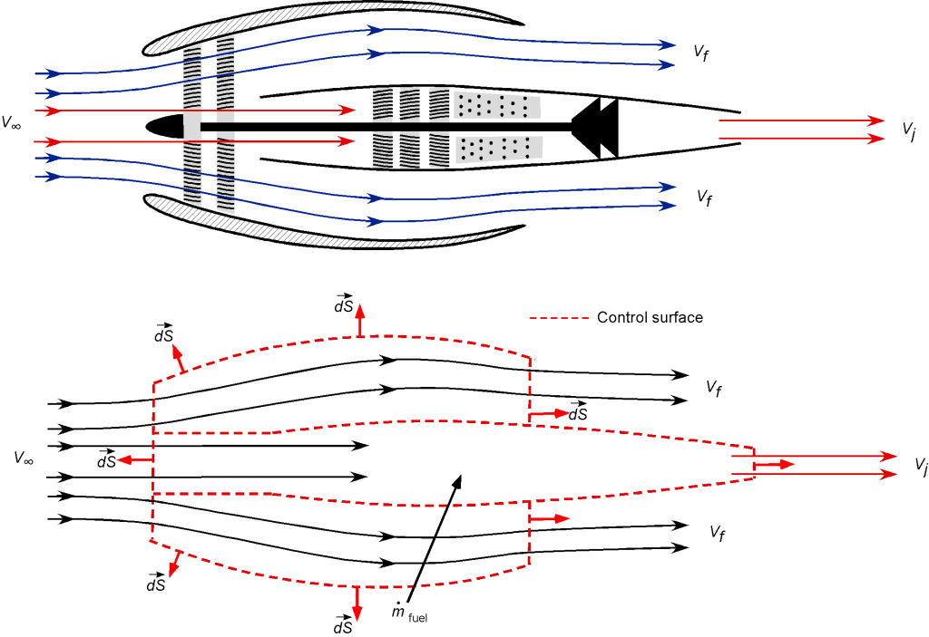
Assume one-dimensional flow throughout the problem. The mass flow through the fan (outer, cold section) is
![\[ \overbigdot{m}_{\rm fan} = \varrho_{\infty} \, A_{\rm fan} V_{\infty} \]](https://eaglepubs.erau.edu/app/uploads/quicklatex/quicklatex.com-9fb421f8263b97cb203e2f5f66570b53_l3.svg "Rendered by QuickLaTeX.com")
The mass flow through the engine core (inner, hot section) is
![\[ \overbigdot{m}_{\rm core} = \varrho_{\infty} \, A_{\rm core} V_{\infty} \]](https://eaglepubs.erau.edu/app/uploads/quicklatex/quicklatex.com-5118d9105c7fd3344b5f49446b5f01c3_l3.svg "Rendered by QuickLaTeX.com")
Because is much smaller than the mass flow of air into the engine, another assumption is that can be neglected.
Therefore, the application of conservation of momentum gives us that
![\[ T_{\rm fan} = \overbigdot{m}_{\rm fan} \left(V_{f} - V_{\infty}\right) \]](https://eaglepubs.erau.edu/app/uploads/quicklatex/quicklatex.com-c4197f775ceaefc16cac8591251832b5_l3.svg "Rendered by QuickLaTeX.com")
and
![\[ T_{\rm core} = \overbigdot{m}_{\rm core} \left(V_{j} - V_{\infty} \right) \]](https://eaglepubs.erau.edu/app/uploads/quicklatex/quicklatex.com-58eb94c16aefba91c3df33c3ee2c4eab_l3.svg "Rendered by QuickLaTeX.com")
where the pressure effects have also been neglected. The bypass ratio (BPR) is given by
![\[ \mbox{BPR} = \frac{\overbigdot{m}_{\rm fan}}{ \overbigdot{m}_{\rm core} } \]](https://eaglepubs.erau.edu/app/uploads/quicklatex/quicklatex.com-a9976fff22f98693bf7e52a90b50bc3a_l3.svg "Rendered by QuickLaTeX.com")
Therefore, the total thrust is
![\[ T = T_{\rm fan} + T_{\rm core} = \overbigdot{m}_{\rm fan} \left(V_{f} - V_{\infty} \right) + \overbigdot{m}_{\rm core} \left(V_{j} - V_{\infty} \right) \]](https://eaglepubs.erau.edu/app/uploads/quicklatex/quicklatex.com-ea693f1251dd499bbe854c803a9f7d2e_l3.svg "Rendered by QuickLaTeX.com")
or in terms of the BPR
![\[ T = \mbox{BPR} \, \overbigdot{m}_{\rm core} \left(V_{f} - V_{\infty} \right) + \overbigdot{m}_{\rm core} \left(V_{j} - V_{\infty} \right) \]](https://eaglepubs.erau.edu/app/uploads/quicklatex/quicklatex.com-e0f0a5e05660cbbbd359bcaac3beb586_l3.svg "Rendered by QuickLaTeX.com")
Notice that the higher the BPR, the higher the thrust from the fan stage of the engine. This is also a more efficient way of producing thrust because for a turbofan, the jet velocity for the fan stage, , is less than that of the core, , i.e.,
![\[ \eta_f = \frac{2}{1 + \displaystyle{\frac{V_f}{V_{\infty}}} } \]](https://eaglepubs.erau.edu/app/uploads/quicklatex/quicklatex.com-aaa01381e36e6f5f08d73783bdadeec2_l3.svg "Rendered by QuickLaTeX.com")
and
![\[ \eta_c = \frac{2}{1 + \displaystyle{ \frac{V_j}{V_{\infty}} }} \]](https://eaglepubs.erau.edu/app/uploads/quicklatex/quicklatex.com-4fb2596f6f33c13cb75552d22145fee5_l3.svg "Rendered by QuickLaTeX.com")
Therefore, the higher the mass flow rate and the lower the jet velocity, the more efficiently the turbojet engine will produce thrust.
Worked Example #5
An aircraft flying at a true airspeed of 200 m/s is powered by a turbofan engine with a bypass ratio of 5:1. The mass flow rate into the engine core is 20 kg/s, and the fuel consumption is 2 kg/s. The average discharge flow velocity from the engine core is = 410 m/s, and from the bypass fan, it is = 270 m/s, both with respect to the engine. Determine the thrust and equivalent power developed by this turbofan engine. Finally, determine the net propulsive efficiency of the turbofan. Neglect all pressure difference effects.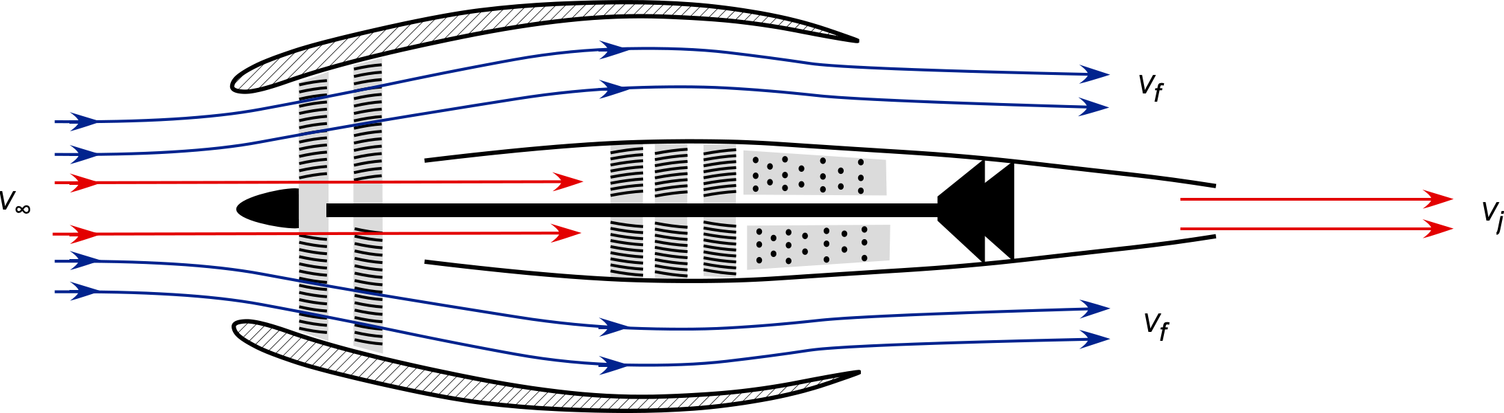
The mass flow of air into the core of the engine is
![\[ \overbigdot{m}_{\rm core} = 20~\mbox{kg/s} \]](https://eaglepubs.erau.edu/app/uploads/quicklatex/quicklatex.com-d09efce2c5e748b00928b3dd34af73a7_l3.svg "Rendered by QuickLaTeX.com")
and with a bypass ratio of 5:1, the mass flow into the fan will be
![\[ \overbigdot{m}_{\rm fan} = 5 \overbigdot{m}_{\rm core} = 100~\mbox{kg/s} \]](https://eaglepubs.erau.edu/app/uploads/quicklatex/quicklatex.com-c9bbb671e2f3055a5f246215391dc425_l3.svg "Rendered by QuickLaTeX.com")
The mass flow rate of fuel is
![\[ \overbigdot{m}_{\rm fuel} = 2~\mbox{kg/s} \]](https://eaglepubs.erau.edu/app/uploads/quicklatex/quicklatex.com-ac58a2b54bb88ed38035fee2824a8435_l3.svg "Rendered by QuickLaTeX.com")
Therefore, the thrust from the engine core is
![\[ T_{\rm core} = (\overbigdot{m}_{\rm core} + \overbigdot{m}_{\rm fuel} ) V_{\rm core} - \overbigdot{m}_{\rm core} V_{\infty} \]](https://eaglepubs.erau.edu/app/uploads/quicklatex/quicklatex.com-cf4529288e8d4dd8c1a0d9b2b43e843b_l3.svg "Rendered by QuickLaTeX.com")
and from the fan, the thrust is
![\[ T_{\rm fan} = \overbigdot{m}_{\rm fan} V_{\rm fan} - \overbigdot{m}_{\rm fan} V_{\infty} = \overbigdot{m}_{\rm fan} \left( V_{\rm fan} - V_{\infty} \right) = 5 \overbigdot{m}_{\rm core} \left( V_{\rm fan} - V_{\infty} \right) \]](https://eaglepubs.erau.edu/app/uploads/quicklatex/quicklatex.com-79765d9ad9b40ac7f5f9ac884f892dc1_l3.svg "Rendered by QuickLaTeX.com")
The total thrust is then
![\[ T = T_{\rm core} + T_{\rm fan} \]](https://eaglepubs.erau.edu/app/uploads/quicklatex/quicklatex.com-c578dc3fef087b45eeb07823323745cc_l3.svg "Rendered by QuickLaTeX.com")
In this case we are given that  = 20 kg/s, = 2 kg/s, and also that
  = 410 m/s,
  = 270 m/s, and = 200 m/s. Therefore, substituting the numerical values gives
![\[ T_{\rm core} = (20.0 + 2.0 ) \times 410.0 - 20.0 \times 200 = 9,020 - 4,000 = 5.02~\mbox{kN} \]](https://eaglepubs.erau.edu/app/uploads/quicklatex/quicklatex.com-da42890f4960dae7f1c77b310de6b919_l3.svg "Rendered by QuickLaTeX.com")
and
![\[ T_{\rm fan} = 5 (20.0) (270.0 - 200.0) = 7.0~\mbox{kN} \]](https://eaglepubs.erau.edu/app/uploads/quicklatex/quicklatex.com-9180a11638b7c518743132ef62603182_l3.svg "Rendered by QuickLaTeX.com")
The total thrust is then
![\[ T = T_{\rm core} + T_{\rm fan} = 5.02 + 7.0 = 12.02~\mbox{kN} \]](https://eaglepubs.erau.edu/app/uploads/quicklatex/quicklatex.com-b05d963c10d95ab1b132f76bf99dd992_l3.svg "Rendered by QuickLaTeX.com")
The equivalent net power,  , that is developed is
![\[ P_{\rm eq} = T V_{\infty} = 12.02 \times 10^3 \times 200 = 2.4~\mbox{MW} \]](https://eaglepubs.erau.edu/app/uploads/quicklatex/quicklatex.com-645d54ca284b5aa04b9baa54babe352b_l3.svg "Rendered by QuickLaTeX.com")
The net propulsive efficiency of the engine is defined as
![\[ \eta_p = \dfrac{\text{Useful power}}{\text{Actual power}} \]](https://eaglepubs.erau.edu/app/uploads/quicklatex/quicklatex.com-9a3fff9cd0c0bf51e0c84701ba173ffd_l3.svg "Rendered by QuickLaTeX.com")
Therefore, for the core and the fan together, then
![\[ \eta_p = \frac{T V_{\infty}}{T V_{\infty} + \frac{1}{2} \overbigdot{m}_{\rm core} \left( V_j^2 - V_{\infty}^2 \right) + \frac{1}{2} \overbigdot{m}_{\rm fan} \left( V_f^2 - V_{\infty}^2 \right)} \]](https://eaglepubs.erau.edu/app/uploads/quicklatex/quicklatex.com-95e17ef5d120222fdccf31158ea6529e_l3.svg "Rendered by QuickLaTeX.com")
Substituting all of the numerical values gives
![\[ \eta_p = \frac{ 12.02 \times 10^3 \times 200 }{2.404 \times 10^6 + 1.281 \times 10^6 + 1.645 \times 10^6} = \frac{2.404 \times 10^6}{5.33 \times 10^6} = 45.1\%. \]](https://eaglepubs.erau.edu/app/uploads/quicklatex/quicklatex.com-858dc655c7d5d204ae6aa0387a06a895_l3.svg "Rendered by QuickLaTeX.com")
Worked Example #6
Refer to the attached propeller charts, which are a standard performance presentation for all propellers. Assume that an actual propeller has a diameter of 7 ft and is a constant-speed propeller with a rotational speed of 2,000 rpm. The propeller operates at an equivalent of 8,000 ft ISA density altitude.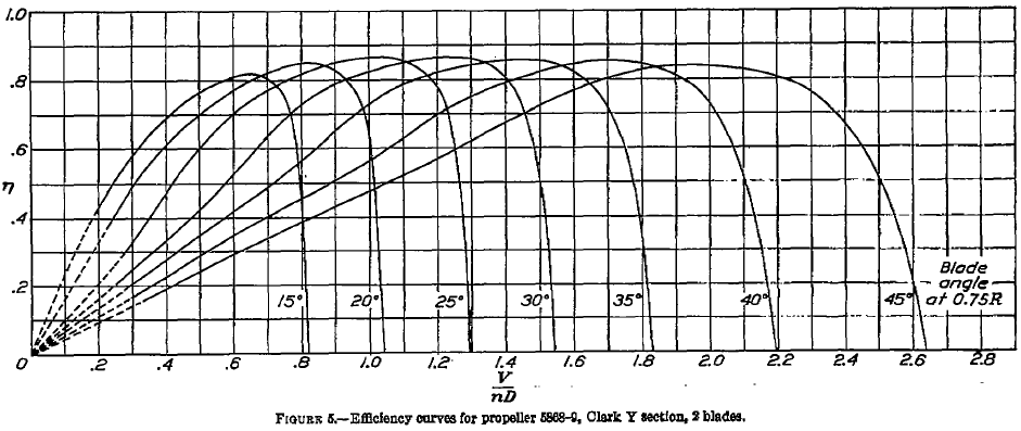
For each blade pitch angle measured at 75% radius and at the point of maximum propulsive efficiency in each case, estimate the following:
(a) What are the advance ratio values and corresponding airspeed values?
(b) What are the propeller thrust coefficient values and the propeller’s corresponding thrust?
(c) What are the values of the propeller power coefficient and the corresponding shaft torque and power required to spin the propeller?
(d) What are the propeller’s helical tip speed values and helical Mach number? Comment on your results. Note: The helical tip speed is the vector sum of the rotational speed at the tip of the propeller and the freestream (airspeed).
(a) At the peak efficiency, the values of the advance ratio can be read off the first chart. We can easily do this to two decimal places; the chart can be digitized for better accuracy. We are also given information about the specific propeller, which is relatively small and would likely be for a general aviation aircraft, so in each case, we can calculate the corresponding airspeed for a given value of  , i.e.,
![\[ J = \frac{V_{\infty} }{n \, d} =\frac{V_{\infty} }{(\text{\small rpm}/60) \, d} \]](https://eaglepubs.erau.edu/app/uploads/quicklatex/quicklatex.com-7e7d23594dd6ab1c6a75215a79f67430_l3.svg "Rendered by QuickLaTeX.com")
so
![\[ V_{\infty} = J \, (\text{\small rpm}/60) \, d = J (2,000/60) \times 7.0 = 233.34 \, J~\mbox{ft/s} \]](https://eaglepubs.erau.edu/app/uploads/quicklatex/quicklatex.com-e0b3ce070732f5c3aef218bf0b8a9477_l3.svg "Rendered by QuickLaTeX.com")
It is best to use a table to show the results, i.e.,
Blade pitch ( ) ) |
 |
|
(ft/s) |
|---|---|---|---|
| 15 | 0.82 | 0.65 | 151.7 |
| 20 | 0.85 | 0.82 | 191.3 |
| 25 | 0.87 | 1.04 | 242.7 |
| 30 | 0.87 | 1.25 | 292.7 |
| 35 | 0.86 | 1.45 | 338.3 |
| 40 | 0.86 | 1.70 | 398.7 |
| 45 | 0.84 | 1.95 | 455.0 |
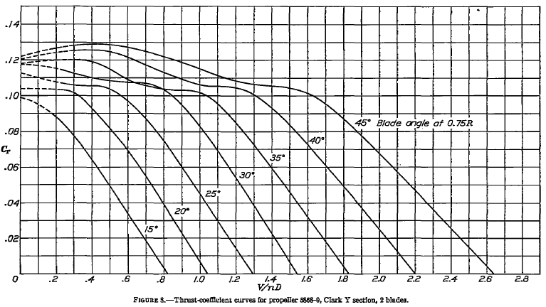
(b) The propeller thrust coefficient can be read off the second chart for each value of the advance ratio, as was identified in the previous part. The thrust coefficient for a propeller is defined as
![\[ C_T = \frac{T}{\varrho n^2 d^4} \]](https://eaglepubs.erau.edu/app/uploads/quicklatex/quicklatex.com-3db77f035fec5ebfd5dca78d590352fb_l3.svg "Rendered by QuickLaTeX.com")
so the corresponding thrust (in units of force) from the propeller is
![\[ T = \varrho n^2 d^4 C_T \]](https://eaglepubs.erau.edu/app/uploads/quicklatex/quicklatex.com-51c295acce7ec434a43dc30371379f13_l3.svg "Rendered by QuickLaTeX.com")
We are told that the propeller operates at the equivalent of 8,000 ft ISA density altitude, so according to the ISA equations, the density at this altitude is 0.001869 slugs ft . Inserting the information gives
![\[ T = \varrho n^2 d^4 C_T = 0.001869 \times \left( \frac{2000}{60} \right)^2 \times 7.0^4 \, C_T = 4986.08 \, C_T \]](https://eaglepubs.erau.edu/app/uploads/quicklatex/quicklatex.com-6e954ad5272b1999c6d4b9707980e40d_l3.svg "Rendered by QuickLaTeX.com")
Again, it is best to use a table to show the results, i.e.,
| Blade pitch () |
|
 |
 |
|---|---|---|---|
| 15 | 0.65 | 0.025 | 124.7 |
| 20 | 0.82 | 0.038 | 189.5 |
| 25 | 1.04 | 0.040 | 199.4 |
| 30 | 1.25 | 0.047 | 234.4 |
| 35 | 1.45 | 0.052 | 259.3 |
| 40 | 1.70 | 0.060 | 299.2 |
| 45 | 1.95 | 0.072 | 359.0 |
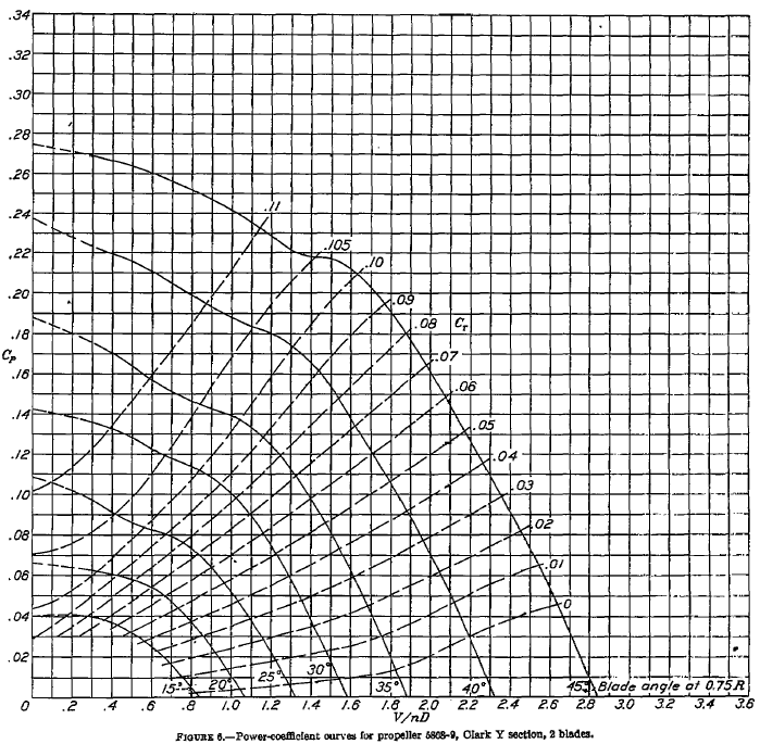
(c) The propeller power coefficient can be read off the third chart for each value of the advance ratio identified in the previous part. The power coefficient for a propeller is defined as
![\[ C_P = \frac{P}{\varrho n^3 d^5} \]](https://eaglepubs.erau.edu/app/uploads/quicklatex/quicklatex.com-b2ab74fab44e673c3efe4d5bf741ce02_l3.svg "Rendered by QuickLaTeX.com")
so the corresponding power needed to drive the propeller is
![\[ P = \varrho n^3 d^5 C_P \]](https://eaglepubs.erau.edu/app/uploads/quicklatex/quicklatex.com-0526df4dd2c2554cda288d4e385a2aee_l3.svg "Rendered by QuickLaTeX.com")
Inserting the known information gives
![\[ P = \varrho n^3 d^5 C_P = 0.001869 \times \left( \frac{2000}{60} \right)^3 \times 7.0^5 \, C_P = 2115.31 \, C_P \]](https://eaglepubs.erau.edu/app/uploads/quicklatex/quicklatex.com-1d53fadac6a46f410b346c7d5deaba99_l3.svg "Rendered by QuickLaTeX.com")
where we have converted to horsepower (hp) by dividing the result in ft-lb s by 550. Again, it is best to use a table to show the results, i.e.,
| Blade pitch () |
|
 |
 (hp) (hp) |
|---|---|---|---|
| 15 | 0.65 | 0.022 | 46.5 |
| 20 | 0.82 | 0.035 | 74.0 |
| 25 | 1.04 | 0.048 | 101.3 |
| 30 | 1.25 | 0.065 | 137.5 |
| 35 | 1.45 | 0.09 | 190.3 |
| 40 | 1.70 | 0.12 | 253.8 |
| 45 | 1.95 | 0.17 | 359.7 |
(d) Let  be the helical tip velocity based on the vector sum of the rotational and airspeed components. The rotational tip speed of a propeller of diameter
  is
is
![\[ V_{\rm tip} = \Omega \left( \frac{d}{2} \right) \]](https://eaglepubs.erau.edu/app/uploads/quicklatex/quicklatex.com-5e4b7fcc4a7dedc2443023b7b8cc28cd_l3.svg "Rendered by QuickLaTeX.com")
where  and so the helical tip speed of the propeller is
![\[ V_{\rm hel} = \sqrt{ V_{\rm tip}^2 + V_{\infty}^2} \]](https://eaglepubs.erau.edu/app/uploads/quicklatex/quicklatex.com-0dca16c84de1c5392e13cdb4574f0a09_l3.svg "Rendered by QuickLaTeX.com")
where is the forward airspeed. The helical Mach number  will be
![\[ M_{\rm hel} = \frac{V_{\rm hel} }{a} \]](https://eaglepubs.erau.edu/app/uploads/quicklatex/quicklatex.com-1c22f43b83b6b9799a906cbae15b97d8_l3.svg "Rendered by QuickLaTeX.com")
where  is the local speed of sound at the conditions at which the propeller operates. At 8,000 ft ISA density altitude,
  1085.3 ft/s.As a final table to show the results, the helical tip speed and Mach number are:
| Blade pitch () |
|
(ft/s) |
(ft/s) |
|
|---|---|---|---|---|
| 15 | 0.65 | 151.7 | 748.6 | 0.69 |
| 20 | 0.82 | 191.3 | 757.6 | 0.70 |
| 25 | 1.04 | 242.7 | 772.2 | 0.71 |
| 30 | 1.25 | 292.7 | 788.9 | 0.73 |
| 35 | 1.45 | 338.3 | 807.3 | 0.74 |
| 40 | 1.70 | 398.7 | 833.5 | 0.77 |
| 45 | 1.95 | 455.0 | 862.8 | 0.79 |
We notice that for an airspeed above 400 ft/s, the propeller blade tips would likely begin to operate near or just beyond the critical Mach number (i.e., the onset of transonic flow), which for the thin tips of propeller blades is about 0.8. Under these conditions, the propeller will likely lose propulsive efficiency.
Worked Example #7
A rocket engine is to be tested on a test stand. The propellant burns at a steady rate of 150 kg/s, and the specific impulse of the propulsion system is 240 seconds. What thrust does the rocket engine develop?
The equivalent exhaust velocity  is given in terms of the specific impulse, i.e.,
![\[ V_{\rm eq} = I_{\rm sp} \, g_0 = 240.0 \times 9.81 = 2,354.4~\mbox{m/s} \]](https://eaglepubs.erau.edu/app/uploads/quicklatex/quicklatex.com-fc831085d1756f900bf7da5c18753b28_l3.svg "Rendered by QuickLaTeX.com")
Therefore, the thrust produced, , will be
![\[ T = \overbigdot{m}_P \, V_{\rm eq} = 150.0 \times 2,354.4 = 353.16~\mbox{kN} \]](https://eaglepubs.erau.edu/app/uploads/quicklatex/quicklatex.com-6c7b8bab5020f6e5669d54f65755a87a_l3.svg "Rendered by QuickLaTeX.com")
Worked Example #8
A rocket engine generates a thrust of 5,000 N and consumes propellant at a rate of 2 kg/s. Calculate the engine’s specific impulse.
![\[ I_{\rm sp} = \frac{\text{\small Thrust}}{\text{\small Rate of propellant consumption}} = \frac{T}{\overbigdot{m}} \]](https://eaglepubs.erau.edu/app/uploads/quicklatex/quicklatex.com-20499ff421c65361f287b70b82cebf5a_l3.svg "Rendered by QuickLaTeX.com")
Inserting the numerical values gives
![\[ I_{\rm sp} = \frac{5,000.0}{2.0} = 250.0~\mbox{s} \]](https://eaglepubs.erau.edu/app/uploads/quicklatex/quicklatex.com-7bd43ff7795d05f4a5f74f9c553f9f8b_l3.svg "Rendered by QuickLaTeX.com")
Worked Example #9
A small rocket engine has a specific impulse of 300 s and operates in a vacuum. If the engine consumes propellant at a rate of 4 kg/s, what is the thrust produced by the engine?
The thrust is given by
![\[ T = \overbigdot{m} V_{\rm eq} = \overbigdot{m} \, I_{\rm sp} \, g_0 \]](https://eaglepubs.erau.edu/app/uploads/quicklatex/quicklatex.com-2ccd83ed69b563c78f0d9673400b87b9_l3.svg "Rendered by QuickLaTeX.com")
Inserting the numerical values gives
![\[ T = 4.0 \times 300.0 \times 9.81 = 11,772~\mbox{N} = 11.772~\mbox{kN} \]](https://eaglepubs.erau.edu/app/uploads/quicklatex/quicklatex.com-52a1a8fdde6d445f0b996afac4a9616e_l3.svg "Rendered by QuickLaTeX.com")
