66 Ground Effect Vehicles
Introduction
Ground Effect Vehicles (GEVs) are designed to operate in close proximity to an impervious surface, such as the ground or water, where the interaction between the airflow and the surface produces a rise in static pressure and a reduction in drag. This phenomenon, known as ground effect, enables the vehicle to generate lift more efficiently and support its weight when flying at low altitudes. GEVs are specifically configured to take advantage of this ground effect regime, and they are often referred to as surface skimmers. They can travel efficiently over flat surfaces without fully flying or floating in the water, which places them outside conventional classifications of airplanes and marine vessels. As such, they occupy a hybrid category requiring distinct design, operational, and regulatory approaches.
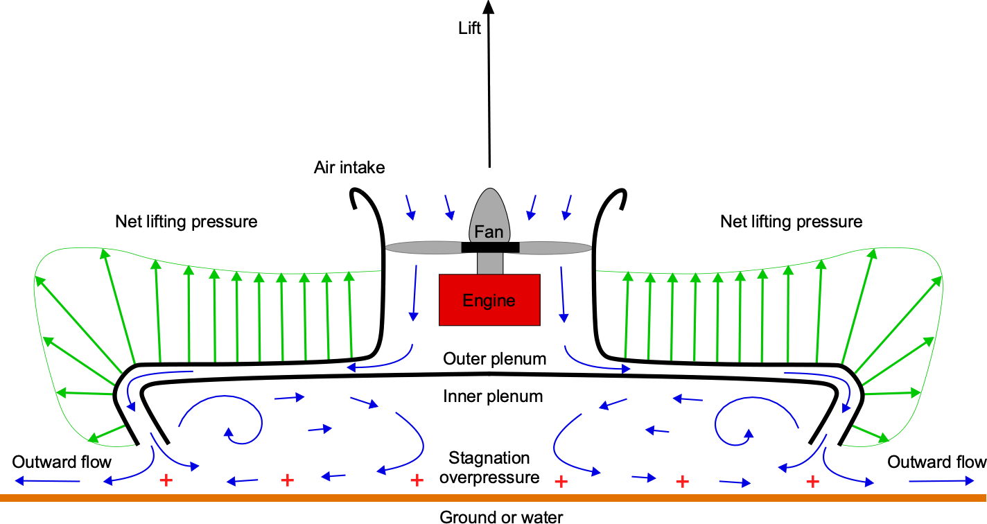
A hovercraft, also known as an air-cushion vehicle (ACV), is one type of ground-effect vehicle (GEV) that creates lift and “flies” using ground effect. The hovercraft rides on a combination of a so-called “cushion” of higher-pressure air below the vehicle inside the inner plenum as well as a jet thrust contribution from a radial “momentum curtain” of downward flow that flows between the inner and outer plenums, as shown in the schematic below. This higher-pressure air and momentum jet originates from an engine driving a fan, for which the excess pressure generated may also be used to direct bleed air through horizontal jets for forward propulsion and control.
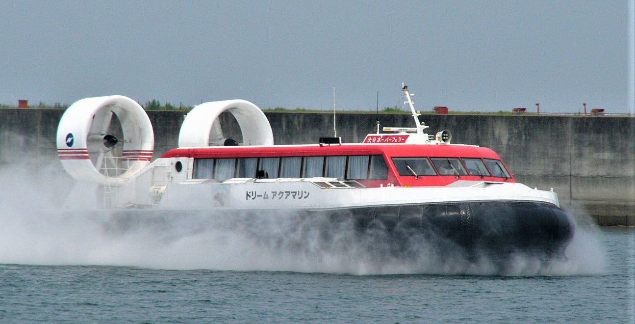
The name “hovercraft” is a trademarked name of Saunders-Roe, an aircraft and maritime engineering company. However, a hovercraft has since become synonymous with all air-cushioned vehicles that can hover free of the ground. An example of a modern hovercraft is shown in the photograph below, which, in this case, is being propelled over water by two ducted fans with steerable rudder vanes, also known as ruddervators. The name “hovercraft” is also known as “Aeroglisseur” (in France), “Luftkissenboot” (in Germany), and “Ground Effect Machine” (in the U.S.).
Hovercraft are operated by a pilot, much like an aircraft rather than a marine vessel. However, the classification of the vehicle as an aircraft per se is debatable. Nevertheless, a hovercraft can fly free of the ground using aerodynamic lift, so it is technically, on the one hand, an aircraft. On the other hand, it can operate over the water as a marine vehicle, so specific additional naval architectural design and seaborne requirements apply, including a need for flotation. Hence, a hybrid vehicle classification for a hovercraft is also appropriate. Hovercraft can travel easily over rough surfaces, including long grass, brush, water, land, mud, and snow, making them rather unusual but highly versatile vehicles for many civil applications and military missions.
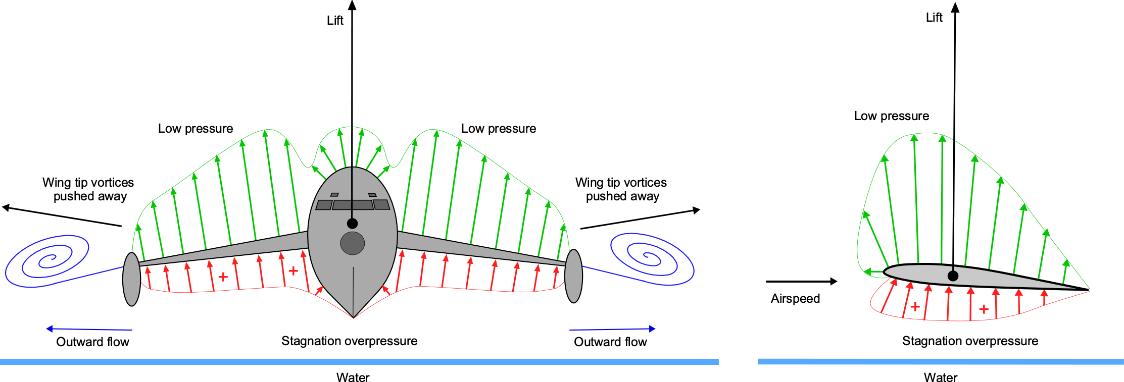
Another type of GEV utilizes the wing-in-ground-effect (WIGE) concept, which operates by riding on a region of higher-pressure air below the vehicle and the ground, creating lift for reasons similar to those of a hovercraft. However, a wing-in-ground-effect (WIGE) vehicle cannot hover and needs forward airspeed to produce lift on its wings; this lift force is significantly increased by the proximity of the wing to the surface, as shown in the schematic below. Besides the increased stagnation pressure below the wings, sometimes referred to as a “ram-air” effect, ground effect pushes the wing tip vortices laterally further away from the wings, significantly increasing their effective aspect ratio and reducing their drag. The upshot of these beneficial aerodynamic effects is that a WIGE vehicle can skim efficiently over the water at airplane speeds, e.g., more than 100 knots, but only if it maintains relatively low altitudes of less than a wingspan.
The concept of WIGE vehicles is not new, and they continue to be explored for military applications, cargo transportation, and even recreational use. Other names for such vehicles include “surface effect ship” and “surface skimmer.” These rather unusual-looking vehicles perform running takeoffs and landings from the water like a seaplane, but they do not have any contact with the water while in “flight.” Some WIGE concepts may also be able to travel over relatively flat ground, similar to a hovercraft, but they are primarily designed for water operations, such as a seaplane; they cannot take off from any other surface.
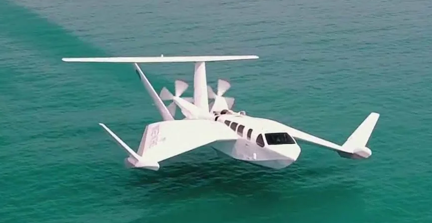
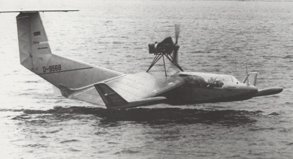
A WIGE design utilizing the “reverse-delta wing” concept, which can also fly out of ground effect, is illustrated in the photograph below. This vehicle skims over water at speeds that are four or five times those of most watercraft. It is unsurprising, therefore, that WIGE vehicles must be operated at least partially in accordance with maritime regulations. Consequently, the International Maritime Organization (IMO) has issued guidelines for wing-in-ground vehicles (referred to as a “WIG craft”) in the context of other marine vehicles, including safety and navigational requirements. Nevertheless, a WIGE vehicle is still technically classified as an aircraft and is generally piloted accordingly, just like a hovercraft, which is considered more of an aircraft than a marine vehicle.
Look! That’s a funny-looking boat! Nope, it’s a funny-looking airplane!
The U.K. aviation authorities remain at odds with the European Union (EU) and the U.S. over the classification and regulation of wing-in-ground-effect (WIGE) vehicles. The U.K. Civil Aviation Authority (CAA) insists WIGE vehicles should be classified as aircraft. In contrast, the European Aviation Safety Agency (EASA) and the U.S. Federal Aviation Administration (FAA) classify WIGE vehicles as marine vehicles. One day, the authorities will sort it all out and reach a consensus. In the meantime, we should be neutral and refer to the concept simply as a “vehicle.” Nevertheless, it might be worthwhile for potential pilots and operators of WIGE vehicles to obtain maritime certifications and a pilot’s license with a seaplane rating.
Learning Objectives
- Review the developmental technical history of ground-effect vehicles (GEVs), such as hovercraft and wing-in-ground-effect (WIGE) vehicles.
- Explore the anatomy and distinctive design features of ground-effect vehicles, as well as their operational principles.
- Study the basic aerodynamic theory behind lift production on hovercraft and other ground-effect vehicles.
- Appreciate the valuable performance characteristics of GEVs and their limitations.
History
Like most flight vehicles, the ideas of developing “ground effect” and “air-cushioned” vehicles go back over a century. John Thornycroft patented an early concept for an air-cushioned boat in 1877, proposing that the air cushion would reduce the surface contact area of the boat’s hull with the water, thereby reducing its drag and increasing its speed over the water. He built a catamaran model and used a bellows mechanism driven by a wound-up spring to trap pressurized air between the two hulls. The resulting overpressure partially lifted the boat out of the water, allowing it to glide just above the surface and markedly increase its speed. Thornycroft needed a powerful engine to make it practical on a bigger scale. Still, it was not until the 1920s, with advancements in internal combustion engines, that proper hovercraft and other GEVs became more viable. In many ways, the availability of engines with high power-to-weight ratios for use in GEVs paralleled the tipping point in the successful development of helicopters.
Hovercraft
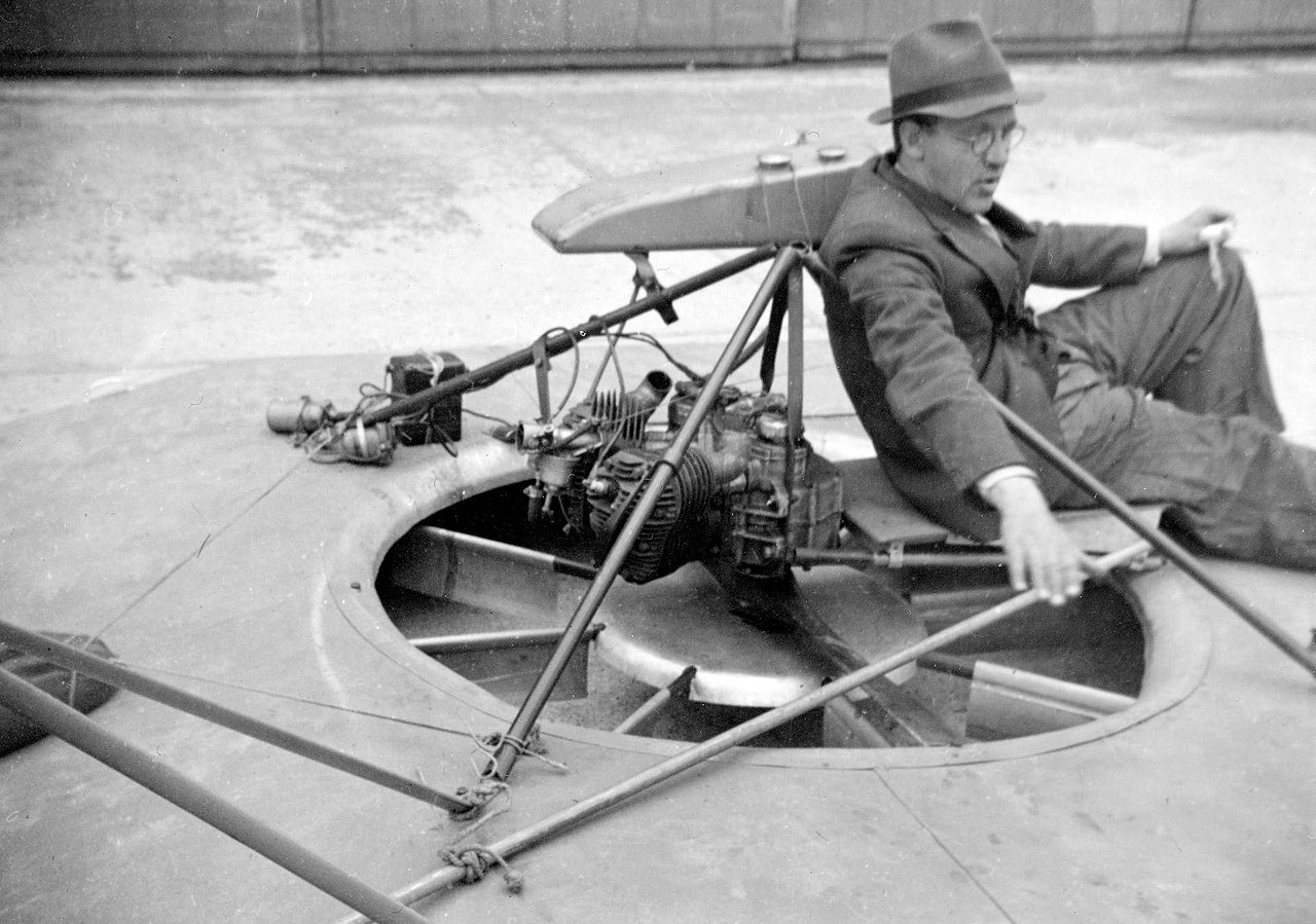
In 1915, Dagobert Müller von Thomamühl modified a speedboat by pumping air into the space below its hull. His idea was similar to that of Thornycroft: to reduce hull drag as the boat traveled over the water. Thomamühl’s modified speedboat reportedly achieved a speed of over 32 knots (59.3 kph), more than twice the speed of the original boat. However, despite being able to lift itself partially out of the water, it could not hover. The availability of suitable engines powerful enough to drive a rotor or fan soon led to designs that created higher-pressure air to form a “cushion” below the vehicle. In 1932, Toivo Kaario is believed to have been the first to develop an air cushion vehicle (ACV) or hovercraft-type ground-effect vehicle utilizing this ground cushion effect. His prototype, dubbed pintaliitäjä (surface hoverer or hovercraft), shown in the photograph below, used a fan driven by a Harley-Davidson motorcycle engine. It was tested until approximately 1935 with some modest success, and although Kaario obtained Finnish patents for the design, further development was halted because of a lack of funding.
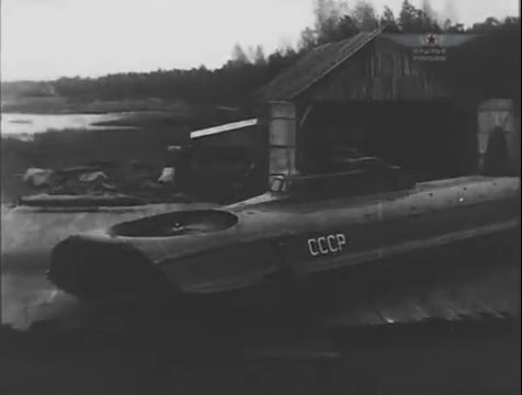
In the mid-1930s, Vladimir Levkov developed a series of ACVs that could hover above ground or water. The L-1 prototype featured a simple design, consisting of a wooden catamaran with two hulls separated by a cavity under pressure, which followed Thornycroft’s ideas and previous work. Further development continued with a series of other prototype machines, each with increasing refinements and performance. One of Levkov’s ACVs, known as the fast-attack L-5 boat or “hover tank,” as depicted in the photograph below, achieved a speed of 70 knots (130 kph); a surviving film of its flights is also available. Levkov led the development of several other ACVs, including the much more capable L-11, but these vehicles were destroyed during WWII. At about the same time, Charles Fletcher in the U.S. designed a hovercraft called a “Glidemobile.” This design also worked on trapping pressurized air in a plenum to lift it from the surface. However, the U.S. government classified the concept shortly after testing, and the prototype was never developed further.
Significant developments in hovercraft technology occurred after WWII. Christopher Cockerell is widely recognized as the pioneer who developed the modern hovercraft. In 1950, he disclosed his ideas of a hovercraft in British Patent GB854211A in which a radial air jet created a reaction “momentum curtain” force and an excess pressure beneath the vehicle, allowing it to hover and travel above ground or water. Cockerell’s design, which added a flexible rubber skirt to trap the air cushion, significantly improved on certain limitations of earlier hovercraft designs. He built a small demonstrator of his hovercraft concept to market it. However, shipbuilding companies claimed his invention was an airplane, and aircraft companies claimed it was a ship, so neither was interested. Nevertheless, a demonstration of the concept before British Government officials led to a grant for further development, but they also declared it top-secret technology.
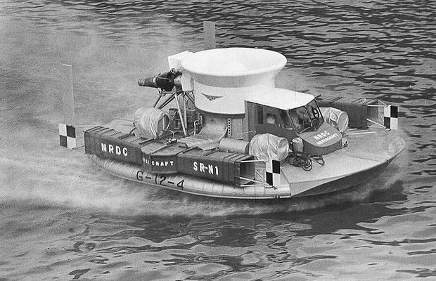
The first technically successful hovercraft was the SR-N1 (Saunders-Roe Nautical Model 1), a demonstrator built under the design leadership of Cockerell, with its first flights made in June 1959. The initial version had a circular structure that resembled a “flying saucer,” a name coined by the press. Later versions featured a bow that was more akin to a boat, designed to aid its movement over water, as shown in the photograph below. It was primarily made of riveted aluminum stressed skin, similar to an aircraft, with a separate buoyancy tank for flotation. It utilized a 450-hp (336 kW) radial aircraft engine that drove a large fan in a duct positioned below an intake nozzle, generating the air cushion beneath the machine and allowing it to hover in ground effect. Directing some bleed air through ducts to nozzles, rudders, or vanes gave translational speed and directional control. The pilots sat in a small cockpit just forward of the duct. The SR-N1 successfully demonstrated hovercraft technology, including a flight across the English Channel, and paved the way for the rapid development of larger and more capable concepts.
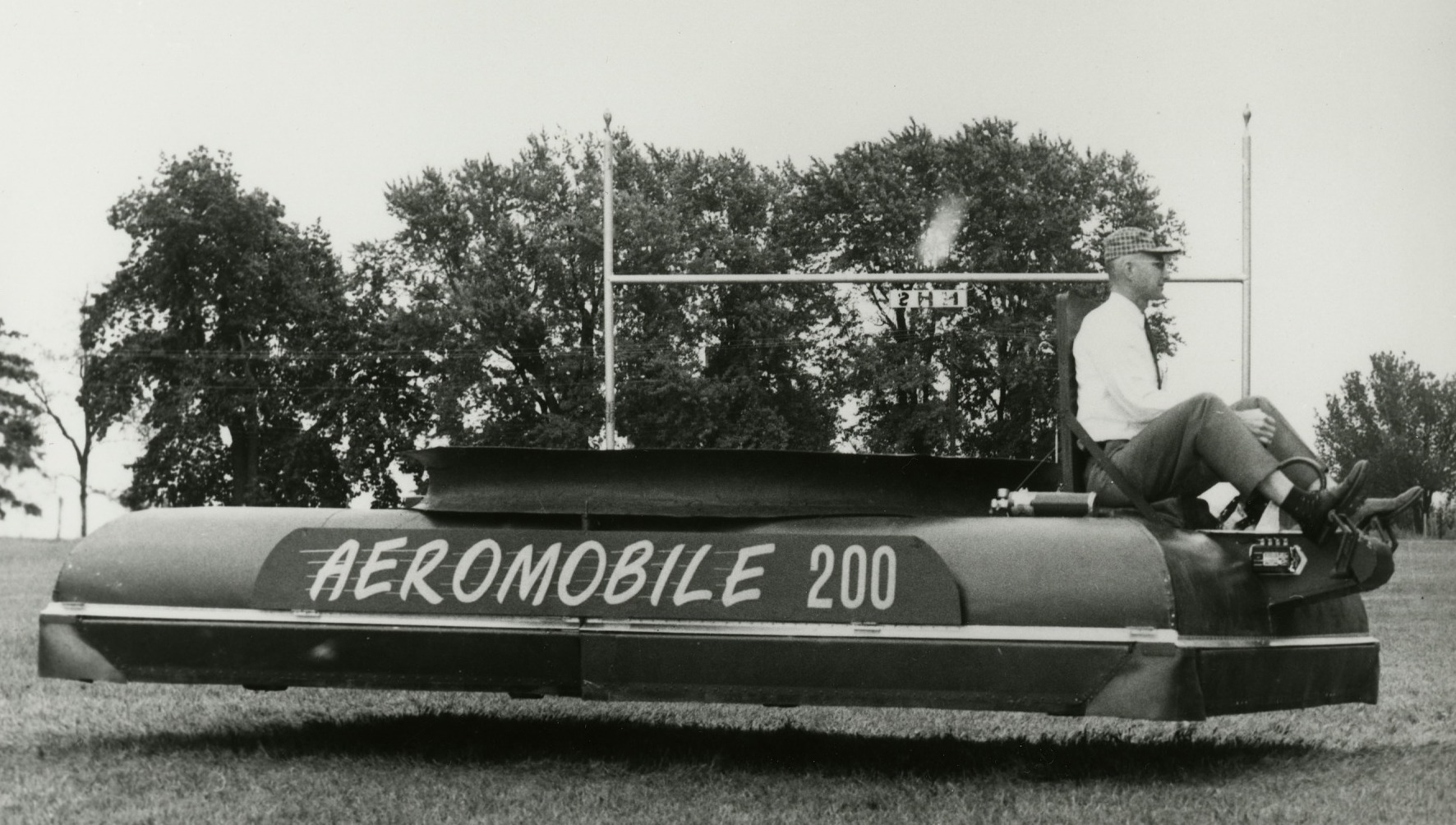
Melville Beardsley developed several hovercraft designs in the 1950s and 1960s and founded the National Research Associates (NRA). NRA developed and tested several ACVs, with the Aqua-GEM being sold in limited numbers. The company also sold several small personal hovercraft, including the “Little Skimmer.” The company was wound up in the late 1960s after being embroiled in patent disputes with the British hovercraft industry. William Bertelsen built a hovercraft concept in 1959 called the Aeromobile 35-B, which was followed by another series of prototype designs, including the Aeromobile-200, as shown in the photograph below. There is also a film of one of his hovercraft traveling down the streets of Chicago. None of his concepts, however, were to go into production.
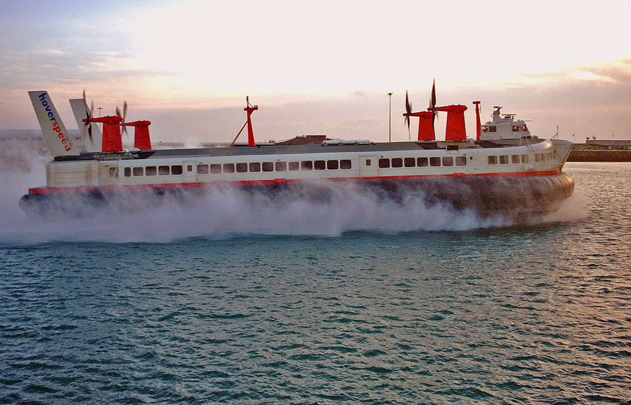
By the early 1970s, the basic hovercraft concept had undergone considerable technical development, and larger, more capable hovercraft began to find several helpful, if niche, roles in both civilian and military applications. The Saunders-Roe company continued to develop a series of hovercraft models with increasing capabilities, including the enormous SR-N4, as shown in the photograph below. The SR-N4 and its variants were used to carry up to 400 passengers and 30 vehicles across the English Channel from Ramsgate and Dover in England to Calais and Boulogne in France, respectively. The SR-N4 weighed over 250 tons and was powered by four turboshaft engines driving variable pitch propellers that could also swivel  30 degrees on azipods. It had a cruise speed over the water of 65 knots, making the cross-channel trip in only 30 minutes, about four times as fast as a regular sea ferry. However, such large hovercraft were operationally expensive and not very profitable. With the opening of the Channel Tunnel in 1994, the last two operational SR-N4 hovercraft became obsolete and were retired in October 2000, marking the end of their impressive 30-year continuous service.
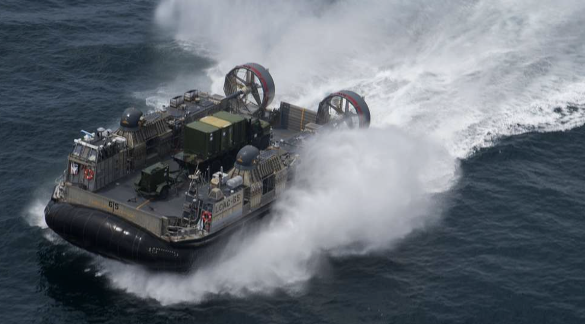
Today, various branches of the armed services, particularly the Marines, utilize hovercraft or air cushion vehicles (ACVs) for amphibious operations and search-and-rescue missions. These ACVs mainly transport personnel, weapons, vehicles, equipment, and cargo over diverse terrain. The photograph below shows the Landing Craft Air Cushion Vehicle (LCACV), a high-speed, hovercraft-style, fully amphibious landing craft. It can carry a payload of up to 70 U.S. tons (63.5 tonnes), such as trucks, support vehicles, and even an M-1 tank, and land on almost any shoreline worldwide. These fantastic vehicles have proved their worth to armed forces worldwide for several decades.
The flexibility and speed of hovercraft over water and other terrain also make them suitable for several important service roles, such as patrols and rescue work. Many manufacturers worldwide supply hovercraft for these purposes. Smaller hovercraft are used in Britain as part of the inshore fleet operated by the Royal National Lifeboat Institute. They have been used, with great success, on large areas of tidal mudflats or sand where the surface is too soft to support land vehicles and the water is too shallow for boats.
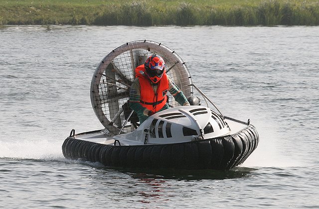
Smaller types of hovercraft are used as recreational vehicles or for fishing and hunting in various terrains. Like their larger counterparts, these hovercraft can easily traverse a wide range of terrain, crossing rivers, lakes, snow, and thin ice. They can reach places often inaccessible by any other vehicle, making them the epitome of amphibious transportation. Some types of single-person sporting hovercraft are used for racing, as shown in the photograph below.
Wing-in-Ground-Effect Vehicles
The first practical application of the wing-in-ground effect (WIGE) phenomenon was demonstrated in 1929 by the enormous Dornier Do X flying boat, which was found to achieve a considerable increase in its flight range by skimming close to the ocean’s surface. In wind tunnel tests, it was also found that the vertical proximity of a lifting wing to a ground surface affected both its lift and drag, with beneficial effects when less than a chord length above the surface. One reason is the reduced induced drag because of the laterally outward movement of the wing tip vortices near the ground. Pilots also became aware of ground effect during the landing flare, which helped cushion the landings. However, if the airspeeds were too high, they would also “float” down the length of the runway.
Rostislav Alexeyev of the Russian Central Hydrofoil Design Bureau developed the first of a series of specifically designed Wing-in-Ground-Effect (WIGE) vehicles, also known as ekranoplans (meaning “screenplanes”). The SM-1, powered by a single jet engine with two lifting wings, took its first flight in July 1961. The improved SM-2, which flew in March 1962, had a single main wing and large vertical and horizontal stabilizers, shown in the photograph below. This vehicle incorporated a secondary turbojet engine in its nose to blow air toward the main wing, thereby creating more lift at lower speeds, known as power-augmented lift. During the Cold War, several other WIGE vehicles were explored for various military applications, including troop transport and anti-submarine warfare; however, none entered operational service. Nevertheless, development activities on such ground-effect vehicles continued through the 1960s.
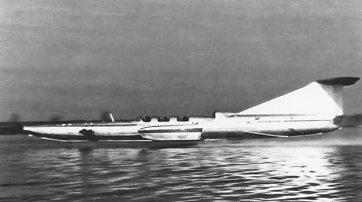
The first flight of the massive KM (Korabl Maket) ekranoplan, as depicted in the photograph below, took place in August 1967. The vehicle had a cruise speed of 267 mph (430 km/h) and a maximum speed of 311 mph (500 km/h). The KM had a gross weight of 544,000 kg (1,199,313 lb), with a range of 1,500 km (932 miles). The aircraft first appeared to observers on satellite images during its trials in the Caspian Sea, its unusual shape raising many questions about its identity and earning it the moniker “Kaspian Monster” or “Caspian Sea Monster.” It underwent trials, as well as various developments and improvements, throughout the 1980s.
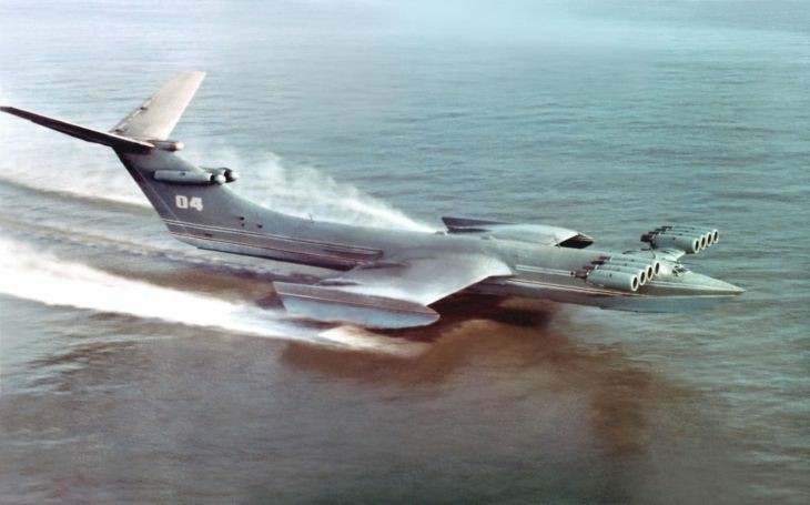
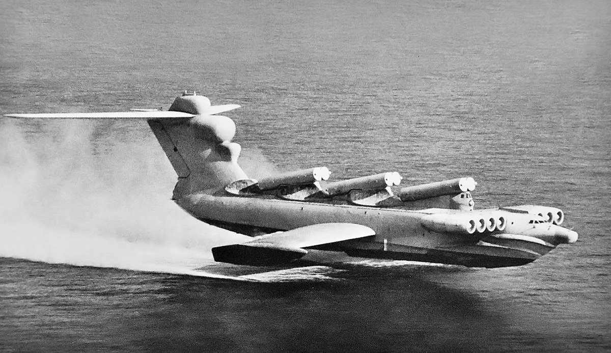
The KM design served as the basis for the Lun-class ekranoplan, developed in the 1980s, which saw one example enter service with the Soviet Navy and later the Russian Navy. This massive missile-carrying S-31 (MD-160) Lun (“Harrier“), as shown in the photograph below, was powered by eight turbojet engines mounted on a foreplane. While only one vehicle was built, it had a maximum takeoff weight of 380,000 kg (837,756 lb), with a payload of up to 137,000 kg (302,000 lb) and a range of 2,000 km (1,243 miles) at a speed exceeding 200 knots. It could launch up to six cruise missiles and was a potentially formidable weapon, able to evade both sonar and radar; fortunately, it was never used in earnest and was retired from service in the late 1980s.
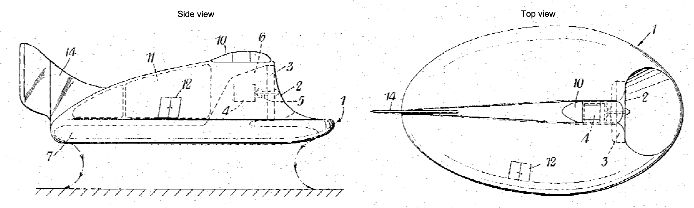
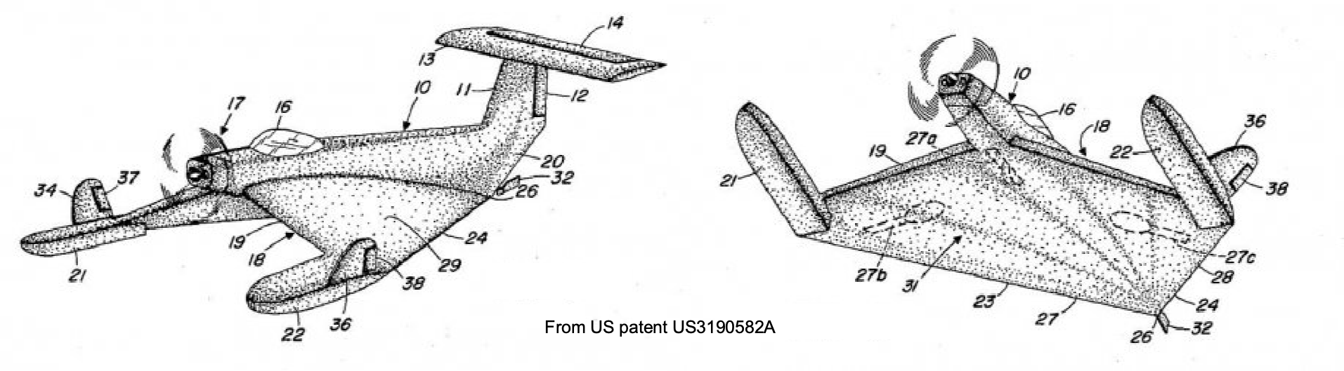
Alexander Lippisch designed a WIGE vehicle in the late 1960s. Lippisch was an ambitious and forward-thinking aeronautical engineer who had initially worked for the Zeppelin company in Germany. Lippisch became interested in tailless and other unorthodox aircraft, and significantly advanced aircraft designs of the WWII era soon followed. His most famous design was the Messerschmitt Me 163 rocket-powered interceptor, which saw limited use during WWII but paved the way for future swept-wing aircraft designs. Lippisch patented a WIGE design featuring a “reverse-delta” wing shape with an unswept leading edge and a highly swept trailing edge, as illustrated in the figure below. Notably, the significant anhedral on the wing also helped capture the air cushion effect.
Lippisch’s patent was sold to Rhein-Flugzeugbau (RFB), resulting in the X-113, as shown in the photograph below. Anhedral on the wing was found to maintain the benefits of ground effect to a higher cruise altitude over the water, allowing it to operate over rougher seas. It even demonstrated its ability to fly well out of ground effect to about 1,000 ft (330 m). The wingtips had winglets to increase the effective aspect ratio of the wings and reduce drag, and wing-tip floats to provide stability on the water. A T-tail fin and tail fin were located at the end of a long dorsal fin, the large tail surfaces giving sufficient stability and control.
One of the adverse characteristics of WIGE aircraft is a relatively significant shift in its center of pressure as it moves in and out of ground effect, leading to pitch instability; therefore, a sizable horizontal tail and good elevator authority are required. The first flight of the X-113 took place in October 1970, and tests continued until 1974; however, the vehicle did not enter production. However, many WIGE vehicles are derivatives of the reverse delta wing concept, such as the Airfish, Eska, and XTW, which have shown that high lift-to-drag ratios of 20:1 are achievable with this type of reverse delta wing.
There has been intermittent interest in WIGE vehicles over the last few decades. DARPA evaluated the Aerocon “Wingship” design as part of a technical study of the WIGE concept for military uses during the 1990s. However, the idea did not progress. In 2002, Boeing’s Phantom Works unveiled a WIGE called the Pelican. It would have been the biggest and heaviest aircraft ever built, but the project seems to have faded into obscurity. However, the WIGE concept has recently received renewed attention from various aerospace companies and government organizations, such as DARPA, which have proposed reconsidering such a surface skimmer ground effect vehicle for efficient, long-range, heavy-lift transport over oceans.
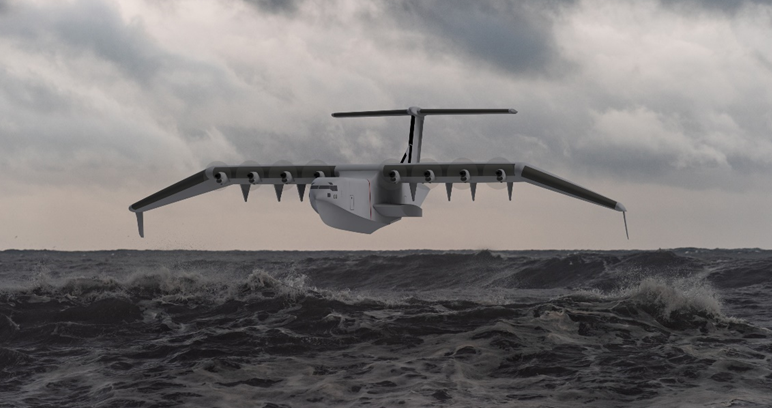
The DARPA Liberty Lifter program aims to develop a vehicle similar in size and payload capacity to the C-17 transport aircraft; an artist’s impression of one concept is shown in the figure below. It remains to be seen whether such a vehicle will be realized, although the benefits of it enhancing the long-reach and “under the radar” military capabilities remain attractive.
Anatomy of GEVs
The anatomy of GEV vehicles, which encompass various hovercraft and wing-in-ground-effect concepts, is somewhat mysterious to most people, including engineers. Their principle of operation is relatively straightforward/ However, the aerodynamics underlying their performance and handling characteristics require a deeper understanding. Both vehicles operate under the well-known “ground cushion” effect, which results from redistributed air pressure below and above the vehicle, leading to an enhanced lift force that helps overcome its weight. It should be noted that even slight pressure differences can generate significant lift forces when acting over large surface areas.
Hovercraft Anatomy
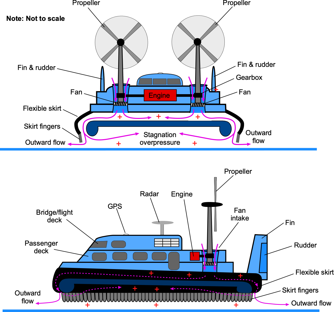
The anatomy of a generic hovercraft is shown in the schematic below. The ground cushion between the vehicle and the surface is created using one or more engine-generated fan combinations. Piston or turboshaft engines can be utilized, although turbocharged marine diesel engines are also popular for modern hovercraft. The fan, sometimes referred to as an impeller, draws in air to increase its static pressure. Either axial or centrifugal fans can be used. The fan must have high efficiency, so it requires carefully designed blades with appropriate airfoil sections, blade twist, and planform shape. This higher-pressure air is channeled and distributed in a plenum beneath the vehicle, creating a lift force that helps the vehicle to rise just above the surface, as illustrated in the figure below.
Lift Fan(s)
While the fan may produce some vertical lift, depending on its design (i.e., axial or centrifugal), this is only a fraction of the lift produced by the increased static pressure below the vehicle. The flexible skirt or curtain produces the remainder of the lift forces, directing airflow as a slightly inward-angled jet that impinges on the surface. The effect provides an additional momentum lift to the vehicle, exceeding the pressure force generated in the plenum, known as the “momentum curtain,” following the concepts proposed by Cockerell.
Increasing the power delivered to the fan increases its rotational speed, resulting in higher static pressure and a greater height above the surface. However, more air escapes below the skirts when this happens, and the pressure cushion effect diminishes. The vehicle reaches an equilibrium height when the bottom of the skirt is a short distance above the surface; the judicious application of engine power can regulate the ride height.
Engines
One or more engines can power a hovercraft. Smaller hovercraft may use one engine with the drive split through a gearbox, delivering power to the lift fan and the remaining power to the propulsion system. Other hovercraft may use ducting to allow one engine to perform both tasks by directing some air to the skirt and the remaining air out of horizontal ducts for propulsion. On a hovercraft with several engines, one usually drives the lift fan, and the other engines drive propellers or fans. Larger, heavier hovercraft may incorporate variable-pitch and reversing-pitch propellers that can swivel on azipods for better performance and control.
Propulsion is a vital aspect of hovercraft design, and modulation of the thrust is essential for forward, backward, and lateral movements. To this end, hovercraft may use differential propeller pitch, rudders, and/or vectored thrust to achieve control. Rudders assist in yaw (directional changes), while vanes located below the fan or inside the plenum can be used to control the mass flow rate from the fan, thereby regulating pressure and providing pitch and roll control. Modern hovercraft may also have control systems that augment stability and responsiveness to control inputs.
Skirt
An essential part of the anatomy of a hovercraft is its flexible rubber skirt, which extends around the periphery of the hovercraft and encapsulates the pressure plenum. A secondary skirt or curtain with inward-pointing, independent, flexible extensions, known as fingers, allows the skirt to deform when striking an obstacle or traversing uneven terrain or choppy seas, minimizing pressure loss below the vehicle. While other concepts may be used, skirts must be flexible and adaptive to accommodate changes in surface contours and maintain an effective seal.
Control
A hovercraft has unlimited directional movement over a surface and is more difficult to control than a boat or a terrestrial vehicle. Therefore, this issue presents unique challenges in its control, specifically determining the machine’s center of gravity (CG) and ensuring it moves in the correct direction. Methods used include aerodynamic control surfaces (e.g., rudders), differential thrust, thrust vectoring, differential plenum pressure, and air jets. Control surfaces, such as rudders, provide an effective and responsive means for directional control in the slipstream of a propeller. However, their effectiveness is reduced at lower airspeeds and low thrusts. Adverse coupling between yaw and roll can occur if the center of pressure of these surfaces is high relative to the c.g. of the vehicle. Another method of control is to use pressurized bleed air, which is ejected through nozzles mounted at appropriate locations to generate yawing moments and side forces. However, their response time is relatively long, so pilots must anticipate the vehicle’s behavior well in advance.
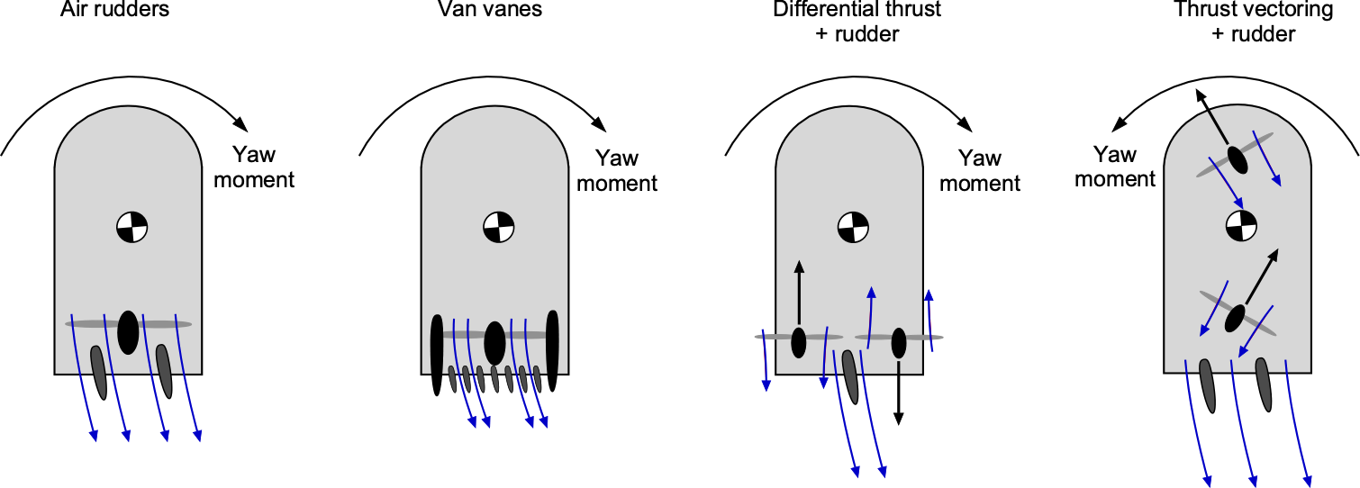
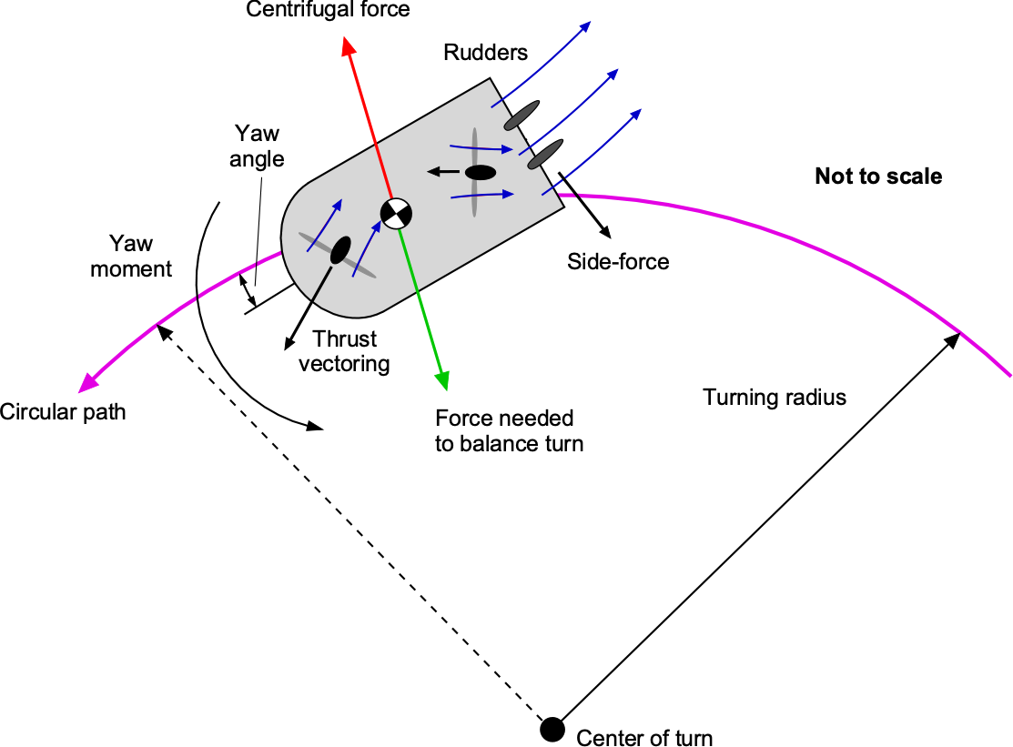
Differential thrust can be produced on twin propellers mounted laterally side by side by controlling the propeller pitch angles and/or rotational speeds. In this fixed, side-by-side propeller configuration, the thrust is parallel to the vehicle’s longitudinal axis, introducing a turning/speed coupling effect. The vehicle must also operate with some yaw angle to generate a lateral force, balancing the centrifugal forces during a turning maneuver, as illustrated in the figure below. Higher centrifugal forces on larger vehicles during turns mean that thrust vectoring is the most effective method for achieving directional control, which can also be balanced using rudders. Water rudders can also be deployed for over-water operations to provide better control and reduce the turn radius.
The yawing moment and side force required for directional (yaw) control can also be generated using fore-and-aft swiveling pylon-mounted propellers on azipods. For some designs, the swivel angle must be limited on either side of the longitudinal axis to limit the magnitude of the adverse rolling moment on the hovercraft relative to its c.g. Compared with the fixed side-by-side propeller arrangement, swiveling pylon-mounted propellers can generate a higher yawing moment because the propellers can be mounted further from the vehicle’s c.g., and less forward thrust is lost for a given yawing moment. Aerodynamic rudders can help balance the turn to minimize the yaw angle, which may need cross-controlled inputs.
WIGE Anatomy
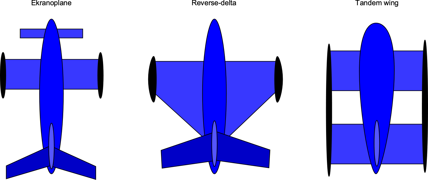
By design, this type of flight vehicle utilizes the benefits of ground effect to lift itself above the water’s surface. However, it still flies close to the surface, typically at a distance less than half its wingspan. Such WIGE vehicles can achieve high cruise speeds over surfaces like water with good aerodynamic efficiency. Much of the power needed from the engines is for takeoff to overcome the hydrodynamic drag from the water. Once airborne and settled at an equilibrium height in the ground effect condition, the drag reduces significantly, allowing the vehicle to cruise relatively fast at a significantly reduced power. Cruise speeds of 200 knots or more are entirely possible. There are three types of WIGE vehicles, as shown in the figure below: an ekranoplan, a reverse delta wing, and a tandem wing. They are distinctive from conventional subsonic airplanes because of their characteristically small aspect ratio of the main wing, the addition of endplates and floats, and unique fuselage/hull shapes that allow them to take off and land on water.
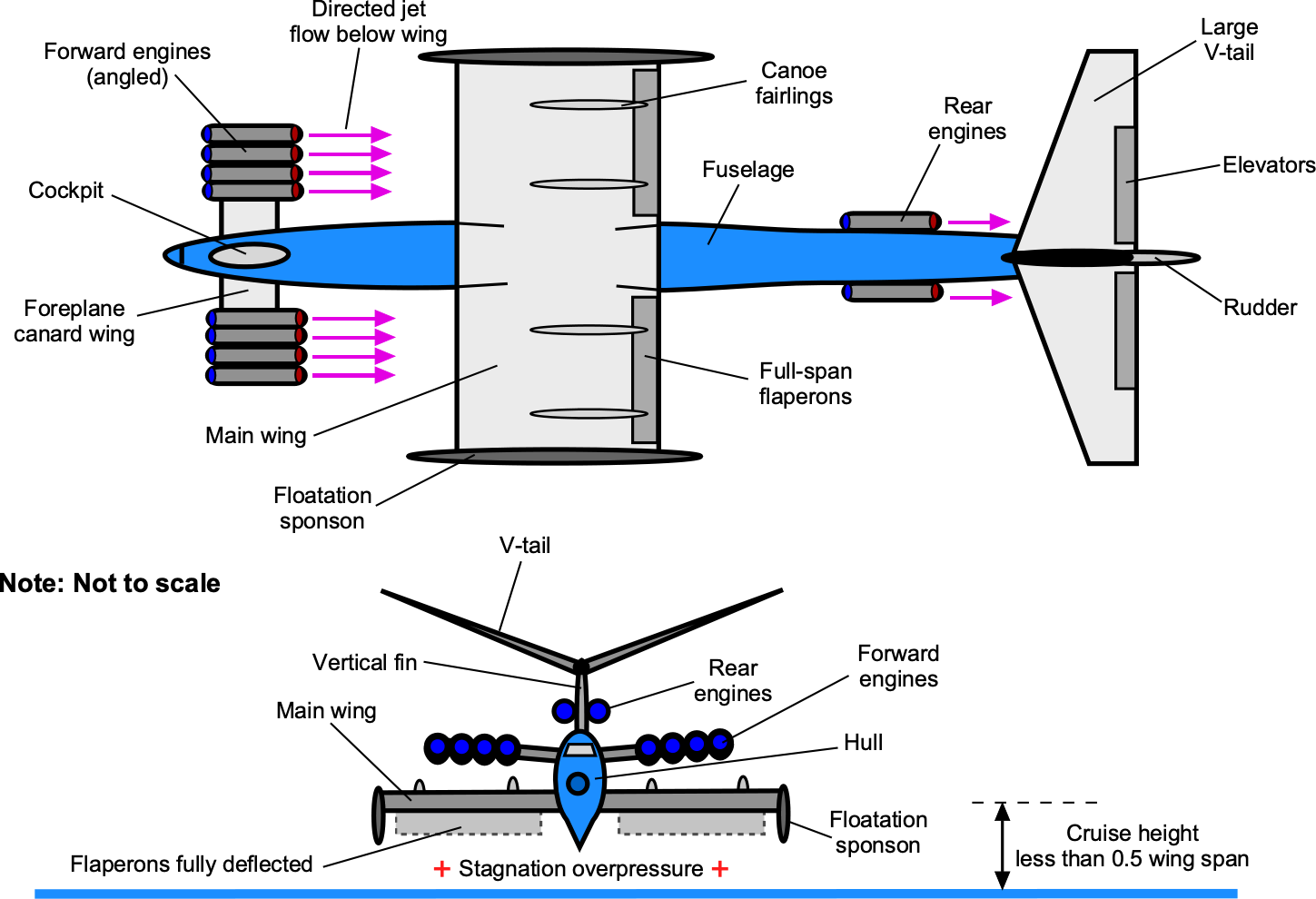
The more detailed anatomy of a wing-in-ground-effect (WIGE) vehicle, also known as an ekranoplane (after the Russian concept), is illustrated in the schematic below. Ekranoplans are typically powered by turbojet or turboprop engines, providing the necessary thrust for lift and propulsion. The number and placement of engines depend on the specific design and size of the ekranoplan. Placing the engines on a foreplane canard allows the jet exhaust to be directed downward toward the wings, increasing their lift. The lift augmentation by the propulsive system can be significant, helping the vehicle transition from the high drag of being seaborne to free flight, similar to an airplane. Full-span trailing edge flaps on the wing help trap the higher-pressure air below the wings, creating the “ram air” effect and reducing the takeoff distance over water.
Wings
Like all WIGE vehicles, ekranoplans have large surface area wings but are relatively short in wing span and have a fairly low aspect ratio, perhaps between 2 and 3. It is well known that higher aspect ratio wings give the least induced drag, but at the price of higher structural weight. However, for a WIGE vehicle, the ground effect condition increases the stagnation pressure below the wing, pushing the wingtip vortices further away from the wing. This effect increases the wing’s effective aspect ratio, providing the benefits of lower induced drag typically associated with a wing of lower aspect ratio, thereby saving structural weight. Flotation sponsons are needed at the tips of the wings, providing the vehicle with lateral stability on the water.
Fuselage/Hull
Like an airplane, the fuselage of a WIGE vehicle houses the cockpit and other essential flight systems, including volume for a payload. However, unlike an airplane, the fuselage must be designed to be aerodynamic and hydrodynamic. Indeed, the hydrodynamic loads on the hull are significant during waterborne operations, and the structure must be designed for increased strength and stiffness compared to an airplane to carry the hydrodynamic loads at the expense of structural weight. The design requirements are similar to those of a seaplane.
Empennage
Like all aircraft, WIGE aircraft have an empennage comprising horizontal and vertical stabilizers. The horizontal tail must have a significant area and control authority to compensate for the change in pitching moment when the vehicle reaches an altitude that exits ground effect. A large dihedral angle on the horizontal tail can significantly enhance lateral stability. At the same time, the main wing typically has either minimal dihedral or even anhedral characteristics, thereby making no direct contribution to stability. Anhedral can help maintain the benefits of ground effect to a greater altitude over the water, which can benefit operations in rough seas.
Control
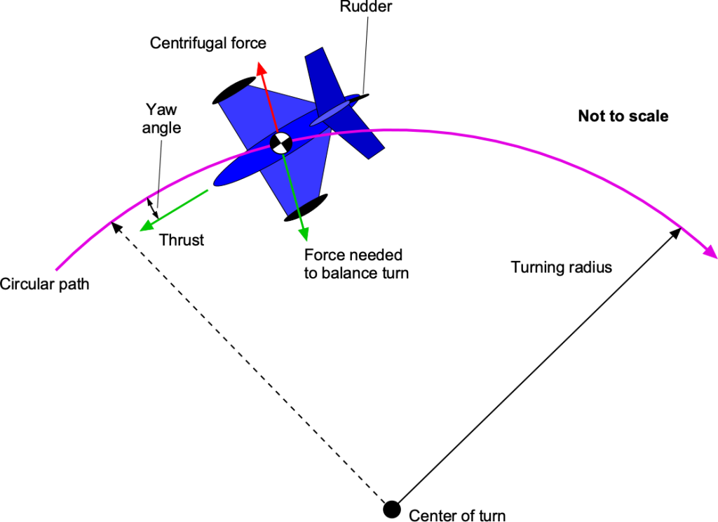
The control of WIGE vehicles is similar to that of hovercraft. Turns are made in a horizontal plane, for which the balance of centrifugal and aerodynamic forces must be considered, as shown in the figure below. Wide-radius skidding turns are the norm, depending on the thrust available and rudder authority. Suppose the vehicle can fly a little higher off the ground or water. In that case, banking using the differential application of the flaperons can increase the bank angle to control the turn. However, the proximity to the ground may severely limit the bank angle.
Hovercraft Performance
Two types of hovercraft require analysis. The first is the pure plenum type, in which the vehicle is lifted entirely by the fan’s increased pressure differential. The second type is the plenum type, augmented by a “momentum curtain” or peripheral jet, where a combination of differential plenum pressure and the reaction force of a peripheral jet impinging on the ground contributes to lift production. It is known that the latter type is preferred for a hovercraft, as it creates more lift; however, both types are worthy of analysis to reveal their performance and design characteristics.
Both can be analyzed, at least initially, by applying the conservation principles of mass, momentum, and energy in their integral forms. The published literature shows that the theory of hovercraft comes up in two different fluid dynamic contexts. The first theory is a plenum discharge analysis originating in internal flow theory. The second comes from the aerodynamic theory for a lift fan. As will be shown, both theoretical approaches yield the same results for the power required to lift a hovercraft off a surface to a specified hover height.
Plenum Discharge Theory
The radial fluid discharge from a plenum chamber forms one mathematical foundation for analyzing the hovercraft. The figure below shows the cross-section of the control volume of a simple hovercraft that uses the pure “plenum” type to lift the vehicle. A fan draws air from the ambient atmosphere at pressure,  , and does work on the air to raise the static pressure by
  , then to a stagnation pressure,
  , inside a plenum of large volume where the flow velocity approaches zero. The resulting differential “cushion” pressure, i.e.,
  acting over the surface area of the plenum, then becomes the primary source of the lift force on the vehicle,
  , to overcome its weight,
  , i.e.,
(1) 
where  is the effective lifting area of the cushion below the vehicle, and
  is the fan area. It can be assumed that the air induced by the fan continuously and steadily escapes from under the vehicle around the periphery of the skirt, a necessary byproduct of creating lift.
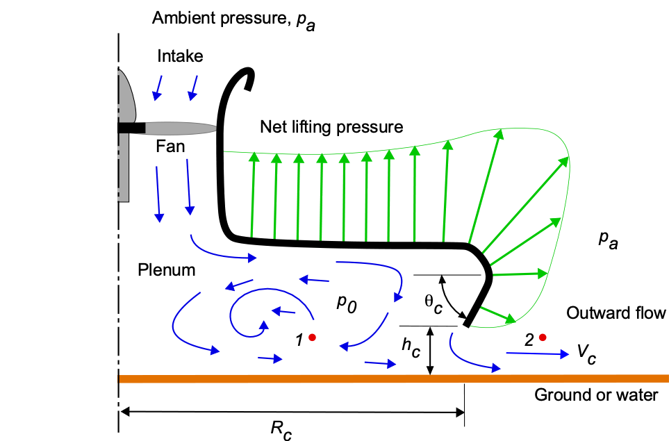
Applying the Bernoulli equation between points 1 and 2, as shown in the figure (above), gives
(2) 
Solving for the discharge velocity  gives
gives
(3) 
The mass flow rate and volume flow rate,  , out from around the perimeter of the plenum depend on the ride height,
  , so that
(4) 
This latter equation is often modified in accordance with hydraulic theory using an effective discharge coefficient,  , i.e.,
(5) 
where  and depends on the wall angle,
  .
.
The resulting “pumping” power required,  , to discharge the air around the perimeter gap will be
(6) 
which, on rearrangement, gives
(7) 
The using Eq. 1 gives
(8) 
which, after simplification, gives
(9) 
without using the discharge coefficient.
Notice that the power required to hover depends on the vehicle’s weight to the power of 3/2 and is also linearly proportional to the hover or ride height, . Additional pressure losses from the intake fan and plenum, as well as frictional losses associated with flow over the ground, can be expected to increase this estimated power by at least 30%. Despite the weight penalty, a power margin of at least 100% would help ensure the hovercraft’s ability to operate under various conditions.
Fan/Plenum Theory
The figure below shows a cross-section of the control volume of a simple hovercraft that uses the pure “plenum” type to lift the vehicle. Assume that the hovercraft has weight and is of the circular airframe shape with a pressure cushion radius of effective radius  . A fan of radius,
  , which is driven by an engine, draws air from the ambient atmosphere at pressure, , and does work on the air to raise its static pressure by , and then to a stagnation pressure, , inside the plenum as the flow velocities approach zero. The resulting differential pressure, i.e., acting over the surface of the plenum, becomes the primary source of the resultant lift force on the hovercraft. The other source of lift is the thrust produced by the fan itself, although, in practice, this contribution is smaller and, in the first instance, can be ignored. Again, it can be assumed that the air continuously and steadily escapes from under the hovercraft around the periphery of the plenum.
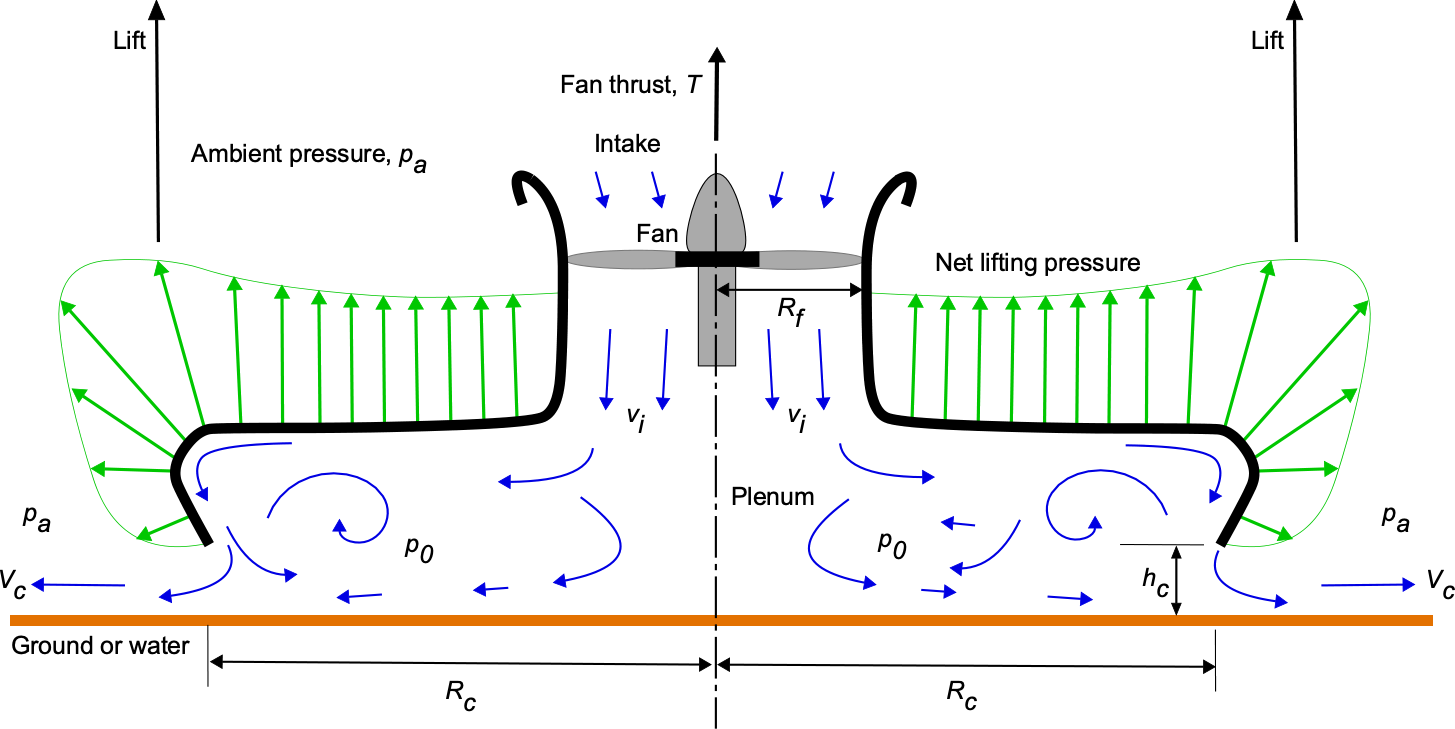
From the conservation of mass, the inlet volume flow rate through the fan must be equal to the exit mass flow rate around the periphery of the plenum, i.e.,
(10) 
Therefore, the relationship between the velocity induced by the fan and the exit velocity below the skirt can be expressed as
(11) 
The fan does work on the air to increase its static pressure by the amount
(12) 
where  is the fan thrust and the ratio
  is the fan disk loading. The fan thrust is obtained by varying its rotational speed as driven by the engine. A gearbox may be installed between the engine and the fan. Notice that lift production from the distribution of the pressure differential in the plenum depends on the disk loading of the fan, i.e., . The higher its rotational speed, the higher the disk loading (for a given fan size), resulting in a higher stagnation pressure in the plenum, which in turn increases the lift on the hovercraft to overcome its weight. Because
(13) 
then
(14) 
For most hovercraft, the ratio  is greater than 10. It will be apparent that a critical attribute of the hovercraft is the ability to distribute the pressure increment induced by the fan over a relatively large surface area, thereby producing more lift on the vehicle than the fan of a given disk area could produce by itself, i.e., the benefits of a low effective disk or surface loading.
The flow velocity induced by the fan,  , depends on the fan disk loading, i.e., for a ducted fan, the relationship is
(15) 
Also, from the conservation of mass, the induced velocity must be
(16) 
Therefore, equating terms leads to
(17) 
The power required by the fan (using conservation of energy) is given by
(18) 
which, after simplification, gives
(19) 
Notice that the result obtained in Eq. 19 is the same as given previously in Eq. 9 using the plenum discharge theory, as it should be because its derivation is based on the same conservation principles. The power required depends on the hovercraft’s weight to the power of 3/2 and the cushion ride height, . Some fan power increases the static pressure in the plenum, and some of it goes into kinetic energy in the flow. This kinetic energy is lost because it escapes from under the vehicle around its periphery, a necessary byproduct of producing the required stagnation pressure.
Check Your Understanding #1 – Power required for a plenum hovercraft
A small plenum-type hovercraft has a weight, , of 4,000 lb. It is of the disk or “saucer” type with a plenum of effective cushion lifting radius, , of 12 ft. The lift fan has a radius of 3 ft. At MSL ISA conditions, estimate the power required for a hover ride height of  ft. Assume a net power system efficiency of 70%.
Show solution/hide solution.
The hovercraft theory gives the power required as
![\[ P_{\rm req} = 2 \pi R_c h_c \left( \dfrac{W}{A_c - A_f} \right)^{3/2} \sqrt{ \dfrac{2 }{\varrho} } \]](https://eaglepubs.erau.edu/app/uploads/quicklatex/quicklatex.com-f4dff8200478ff836511fece675a6281_l3.svg "Rendered by QuickLaTeX.com")
assuming a discharge coefficient of unity. Inserting the numerical values gives
![\[ P_{\rm req} = 2 \pi \times 12.0 \times 1.0 \left( \dfrac{4,000}{\pi ( 12.0^2 - 3.0)^2} \right)^{3/2} \sqrt{ \dfrac{2 }{0.002378} } = 63,334.7~\mbox{ft-lb s$^{-1}$} = 115.15~\mbox{hp} \]](https://eaglepubs.erau.edu/app/uploads/quicklatex/quicklatex.com-feada11721fc11dbe2f6f31ac32172ad_l3.svg "Rendered by QuickLaTeX.com")
where MSL ISA density is 0.002378 slugs/ft3. If losses give a net system efficiency of 70%, the power required will increase to 115.15/0.70 = 164.5 hp.
Peripheral Jet Theory
The figure below shows the cross-section of a hovercraft that uses the “momentum curtain” type. Again, assume that the hovercraft has weight and is of the circular “flying saucer” type with an effective pressure cushion of radius . In this case, the fan operates on the air that flows through the volume between the inner and outer plenums. The resulting flow provides “jet” thrust as it exhausts vertically downward through a plenum gap of width  , which then impinges on the ground around the vehicle’s periphery. In this case, the momentum jet reaction enhances the lift production on the hovercraft beyond that produced by the stagnation overpressure in the plenum.
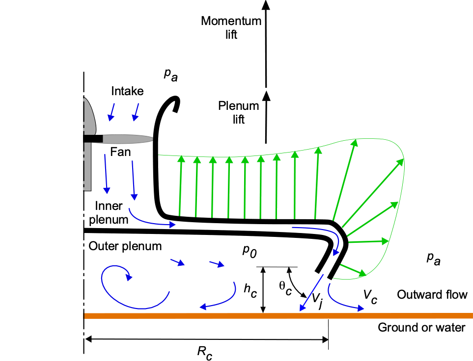
The “momentum” lift force from the peripheral momentum curtain,  , depends on the time rate of change of momentum of the flow as it is brought to zero at the surface of the ground or the water. The area of the flow at the exit,
  , is given by
(20) 
which can be approximated as
(21) 
if is small compared to . Conservation of mass means that the mass flow rate out of the jet equals the mass flow rate into and through the fan, i.e.,
(22) 
so that
(23) 
The momentum force (lift) augmentation, , on the hovercraft is then
(24) 
when assuming the jet velocity is turned in a direction parallel to the ground, there are otherwise no other momentum losses. The induced velocity at the fan is
(25)
so the lift augmentation is
(26) 
The fan does work on the air to increase its static pressure by the amount
(27) 
Finally, a relatively simple result for the momentum thrust augmentation is obtained, i.e.,
(28) 
If it is further assumed, based on the plenum pressure contribution to the lift, that
(29) 
then, the final result for the lift from momentum thrust is
(30) 
Check Your Understanding #2 – Lift augmentation for a “momentum curtain” hovercraft
For the hovercraft assumed in Example #1, estimate the additional lift augmentation using the “momentum curtain” effect. Assume that  and the curtain jet has a width of = 0.25 feet.
Show solution/hide solution.
The momentum lift augmenting is given by
![\[ L_m = 2 W \left( \frac{R_f^4}{R_c w (R_c^2 - R_f^2)} \right) \sin \theta_c \]](https://eaglepubs.erau.edu/app/uploads/quicklatex/quicklatex.com-d3f505e85a1f949b71c650fa1e8a8499_l3.svg "Rendered by QuickLaTeX.com")
Inserting the numerical values gives
![\[ L_m = 2 \times 4,000 \left( \frac{3.0^4}{12.0 \times 0.25 \times (12.0^2 - 3.0^2)} \right) \sin 75^{\circ} = 1,016.5~\mbox{lb} \]](https://eaglepubs.erau.edu/app/uploads/quicklatex/quicklatex.com-56133e20330612e3579b8867adebe8ad_l3.svg "Rendered by QuickLaTeX.com")
Therefore, with all other parameters remaining the same and having the same power, the gross weight of the hovercraft could be increased from 4,000 lb to 5,000 lb, representing approximately a 25% increase.
Forward Motion of a Hovercraft
Besides lifting fans, a hovercraft must have some form of propulsion to overcome aerodynamic drag and other sources of resistance, allowing it to move over the ground or water. There are several drag components, some unique to hovercraft, which must be considered when estimating the performance of such a vehicle in forward motion. In addition to the parasitic drag on the hovercraft, there are contributions from momentum drag, trim drag, and skirt contact drag. For overwater operations, wetting drag and other sources of hull drag from waves must also be considered. Therefore, the drag buildup for a hovercraft is more complicated than for an airplane because it requires accounting for both aerodynamic and hydrodynamic effects, as well as various vehicle, ground, and water interactional effects, which are difficult to quantify.
The use of flexible skirts of various designs has permitted a considerable reduction in ride height, reducing the power required. However, a lower clearance height may increase the contact drag between the skirt and the surface, thereby increasing the drag on the vehicle and the propulsive power. In hovercraft design, there must be a good balance between the power installed for lift and propulsion, which affects the total power requirements for movement over a given surface at a certain weight and speed. Sufficient thrust and power margins are necessary to prevent overestimating performance, allowing the hovercraft to travel over a broad range of terrain and sea states.
Aerodynamic Parasitic Drag
All vehicles create aerodynamic parasitic drag when moving through the air, denoted as  . This drag component can be calculated using the standard drag formula
(31) 
where  is the “airspeed” of the hovercraft over the surface, and
  is the drag coefficient of the specific shape of the hovercraft. Most hovercraft are not particularly streamlined, partly for utility, nor do they need to be because they operate at relatively low speeds compared to airplanes. Drag coefficients for hovercraft shapes have been obtained from wind-tunnel tests and have been found to range in value from 0.25 to 0.4 where
  is based on the reference of frontal area. However, instead of using drag coefficients and the ambiguity of what is meant by a reference area, it is often useful to represent the drag in terms of equivalent drag area,
  , where
  , i.e.,
(32) 
Skirt Contact Drag
While a hovercraft is designed to have a cushion height and a skirt clearance, there can still be some contact between the rubber skirt and the terrain under certain conditions. Therefore, the manifestation of this contact is a drag component known as the skirt contact drag,  . Contact mainly occurs when the hovercraft travels over rough terrain, such as tall grass, vegetation, or brush. This source of drag will also depend on the cushion height, which can be represented as
(33) 
where  is a drag coefficient at a certain cushion height. Notice that skirt contact drag is analogous to a friction force, which depends on weight, not forward speed.
There are no reliable methods to predict this drag component other than semi-empirical rules derived from experiments. However, available results suggest that for average cushion heights, the value of varies from approximately 0.01 over smooth surfaces, such as concrete or short grass, to as much as 0.05 for long grass, vegetation, or brush. In some cases, increasing the lifting fan power can increase the cushion height and reduce the drag from skirt contact.
Momentum Drag
When a hovercraft is moving forward over ground or water, the air exiting around the perimeter of the plenum that produces the “momentum curtain” is redirected by the effects of the airspeed, . The upshot of this behavior is a form of extra drag known as momentum drag. The equation used to account for the momentum drag is
(34) 
where is the volume flow rate through the air cushion system, i.e.,
(35) 
However, the creation of momentum drag is offset by the increased dynamic pressure at the intake to the lifting fan. While no rigorous methods exist to calculate such effects, this latter effect may reduce momentum drag by as much as 50%. Compared to other sources of drag on a hovercraft, the momentum drag contribution is relatively small, and its explicit contribution can be neglected in preliminary analyses.
Trim Drag
If the bottom of the hovercraft is not horizontal to the surface, i.e., it is tilted forward or backward, then there will be a horizontal component of the lift force (equal to weight) that will contribute to the drag, i.e.,
(36) 
where  is the angle between the cushion base and the surface, which could be nose-down or nose-up. Therefore, trim drag can be a thrust or a drag, depending on the trim state. Because the trim state will also affect skirt contact drag, the weight and balance of the hovercraft must be properly maintained.
Overwater Drag
For overwater operations, there will be additional drag contributions on the hovercraft, including wetting drag and drag from waves. Wetting drag is similar to the effects of skirt drag over the ground, but this drag source depends on the degree of water contact and the volume of water spray hitting the skirt. The factors affecting wetting drag will include the cushion height, vehicle size and shape, and vehicle speed. Empirical data are usually used to estimate overwater drag, which is primarily a hydrodynamic problem. Drag on watercraft from waves, for example, depends on the Froude number and the size and length of the waves, so the effects obtained on drag become a nonlinear function of speed over the water.
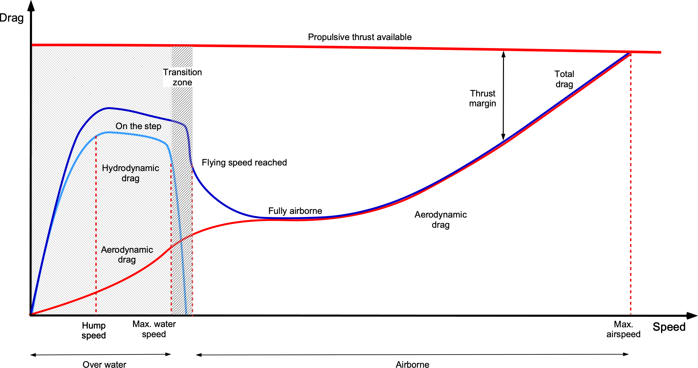
Notice that there is a speed at which the hydrodynamic drag reaches a maximum, often referred to as the “hump” speed. This form of drag is usually referred to as wave-making drag. This condition occurs when the length of the wave created by the bow matches the curtain diameter of the hovercraft, which is equivalent to the hull waterline length for a boat. Significant thrust is required to exceed the hump speed, which pilots usually refer to as “getting on the step,” but after that, the drag will decrease as the hovercraft skims over the waves.
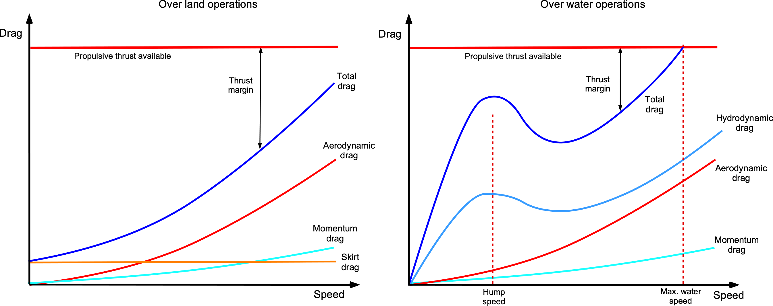
Total Drag
The aggregate contribution of all drag sources is shown qualitatively in the figure below. Notice that power is the product of drag and speed; for example, the parasitic power increases with the cube of speed. Overwater operations significantly increase the drag on the vehicle, so the thrust and power required increase commensurately. Therefore, because of the complexity and higher quantitative uncertainties in the drag buildup on a hovercraft, significant power margins are typically introduced into its design, which results in some increased weight and cost. However, any significant underestimation of the required installed power could have a major impact on the hovercraft’s ability to operate in conditions for which it would otherwise be expected to operate.
Check Your Understanding #3 – Estimating the propulsive power for a hovercraft
For the small hovercraft considered in the previous worked examples, estimate the thrust and power required to propel it over tall grass at a speed of 30 knots under MSL ISA conditions. Assume an equivalent parasitic drag area of 30 ft , a skirt contact drag coefficient of 0.045, and a net propulsive efficiency of 0.7. Neglect the momentum drag component.
Show solution/hide solution.
The total drag on the vehicle will comprise the sum of contributions from aerodynamic drag, momentum drag, and skirt contact drag. The aerodynamic drag is
![\[ D_a = \frac{1}{2} \varrho\, V_{\infty}^2 \, f_e = \frac{1}{2} \times 0.002378 \times (30.0 \times 1.688)^2 \times 30.0 = 91.47~\mbox{lb} \]](https://eaglepubs.erau.edu/app/uploads/quicklatex/quicklatex.com-a869af98ca54633777b6074e478d1635_l3.svg "Rendered by QuickLaTeX.com")
The skirt drag is
![\[ D_{\rm sk} = C_{\rm sk} W = 0.045 \times 4,000 = 180.0~\mbox{lb} \]](https://eaglepubs.erau.edu/app/uploads/quicklatex/quicklatex.com-bbd703c88c144d33208f6e55b656d9d9_l3.svg "Rendered by QuickLaTeX.com")
Therefore, the total drag is
![\[ D = D_a + D_{\rm sk} = 91.47 + 180.0 = 271.47~\mbox{lb} \]](https://eaglepubs.erau.edu/app/uploads/quicklatex/quicklatex.com-4b92da2ef3de767a2596d787012f06c8_l3.svg "Rendered by QuickLaTeX.com")
and the power required to generate the needed thrust will be
![\[ P_{\rm req} = \left( \frac{1}{\eta_p}\right) D \, V_{\infty} = 271.47 \times 30.0 \times 1.688/0.7 = 19,600.53~\mbox{ft-lb/s} = 35.64~\mbox{hp} \]](https://eaglepubs.erau.edu/app/uploads/quicklatex/quicklatex.com-967b065f6cea326dc31a2c43136fb1bc_l3.svg "Rendered by QuickLaTeX.com")
Hovercraft Stability
The interaction between air cushion pressure, vehicle geometry, and the dynamic response to external disturbances governs the stability of a hovercraft. The primary modes of motion relevant to stability analysis are similar to those of a flight vehicle: heave (vertical motion), pitch (tilting forward or backward), and roll (tilting side to side). Stability in each mode depends on whether the resulting forces and moments act to restore the hovercraft to its equilibrium state after a disturbance.
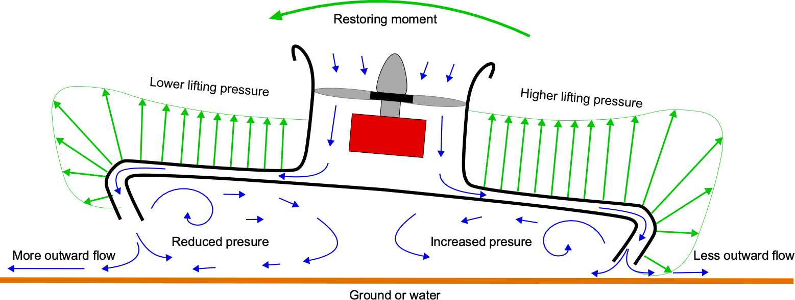
The skirt also gives an inherent pitch and roll stability to a hovercraft. For example, suppose a disturbance causes the vehicle to pitch or roll, as shown in the figure below. In that case, the distance from the bottom of the curtain to the ground increases on one side, allowing more air to escape and thereby reducing pressure, while less air escapes on the other side, increasing pressure. The net effect, therefore, is a restoring moment on the vehicle that will cause it to self-right itself. However, there may be a considerable lag in the buildup of the restoring moment because of the vehicle’s inertia.
Improved roll and pitch stability, as well as a finer level of control, can also be achieved by inflating compartments that divide the skirt and, consequently, the ground cushion into separate compartments. The air pressure can then be modulated to obtain pitch and roll control. Proper weight distribution is also crucial for stability and control. An evenly distributed load helps prevent tilting or leaning to one side; therefore, pilots must ensure that the vehicle is loaded within its defined weight and balance envelope. Sometimes, hovercraft can be equipped with water ballast systems to adjust their weight distribution. Hovercraft designed for maritime use also need to exhibit good sea-keeping abilities, especially in their ability to negotiate waves.
Heave (Vertical) Stability
In the vertical direction, the hovercraft hovers when the cushion pressure , acting over the effective cushion area  , generates a lift force equal to the vehicle’s weight, i.e.,
(37) 
To achieve static stability, the lift must decrease with upward displacement, ensuring that any vertical disturbance results in a net restoring force, i.e.,
(38) 
This goal is typically achieved through increased air leakage as the hovercraft rises, which reduces the cushion pressure. Damping forces arising from skirt dynamics or airflow behavior will also oppose rapid vertical oscillations. The vertical equation of motion is then
(39) 
where  represents the vertical damping. A design goal is to provide the hovercraft with sufficient heave damping to ensure a smooth ride over most surfaces. To this end, the skirt design is critical for enabling controlled pressure relief and providing damping.
Pitch & Roll Stability
Pitch and roll stability arise from asymmetries in the cushion pressure distribution when the hovercraft tilts. The side of the cushion that moves closer to the ground experiences increased air leakage, resulting in reduced pressure and lift on that side. This imbalance generates a restoring moment that resists further tilting. The rotational dynamics are given by
(40) 
where  and
and  are the moments of inertia about the pitch and roll axes, respectively, and
  and
and  are the corresponding restoring moments. Static stability requires these moments to oppose the motion, i.e.,
(41) 
A low and centrally located c.g. position improves resistance to tipping by minimizing destabilizing moments during pitch or roll. Additionally, the air cushion system must respond smoothly to changes in pressure distribution, such that any disturbance results in restoring forces and moments. Together, these features contribute to the hovercraft’s ability to maintain a stable hover and consistent orientation during regular operation.
WIGE Vehicle Performance
Flight performance estimates for a WIGE vehicle follow the same fundamental principles as those for an airplane. However, in this case, the challenge is quantifying the additional aerodynamic effects from flow interactions caused by flying near the ground. While various corrections can be applied, the most representative results are likely to be obtained from wind tunnel tests using scaled models. The diverse types and sizes (flight weights) of WIGE concepts, combined with sparse empirical data, make it challenging to rely on historical trends to establish specific design rules.
A critical issue to consider in predictions is that when a finite wing or lifting surface approaches the ground or another impervious surface, it experiences an increase in lift and a reduction in drag, resulting in improved overall aerodynamic efficiency. There are two causes of the increase in lift. The first source is the change in the flow field around a wing cross-section, which increases the lower surface pressure and the effective angle of attack, sometimes referred to as a ram air effect. The other impact is caused by the laterally outward movement of the wing tip vortices, which manifests as an increase in the effective aspect ratio of the wing and, hence, a reduction in induced drag. The combined effect of both factors is an increase in lift and a decrease in drag on the wing, thereby enhancing its lift-to-drag ratio and improving the aircraft’s aerodynamic efficiency. Some WIGE vehicles have been estimated to have lift-to-drag ratios of more than 20, which is higher than many aircraft.
Ram Air Effect
The “ram air” effect typically refers to the increase in stagnation pressure on the lower surface of a wing when flying in proximity to the ground. This beneficial effect results from the alteration of airflow patterns around the wing, leading to increased lift. Further improvements in aerodynamic efficiency arise from the lower suction pressure around the airfoil’s leading edge. These two effects on wing characteristics help enable a WIGE vehicle to maintain flight with improved aerodynamic efficiency, thereby reducing power requirements and fuel consumption. The primary effects are illustrated in the figure below.
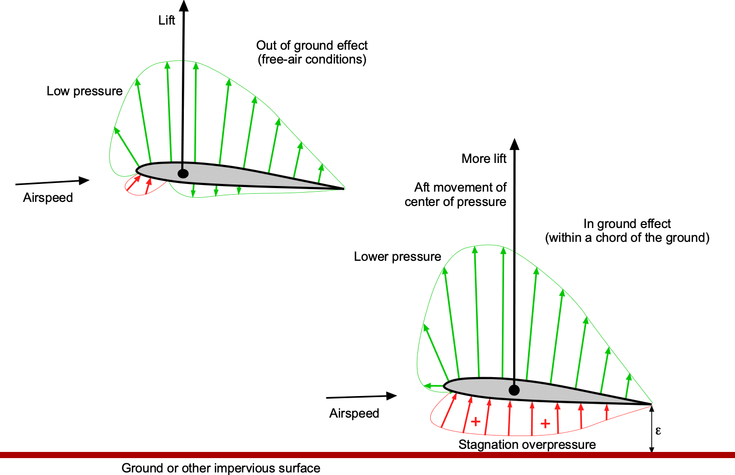
The ram air effect depends primarily on the distance between the trailing edge of the wing and the ground,  , so a wing needs to get within one chord length to experience the benefits. Full-span trailing edge flaps can further reduce , as seen on ekranoplans, thereby enhancing the ram air effect.
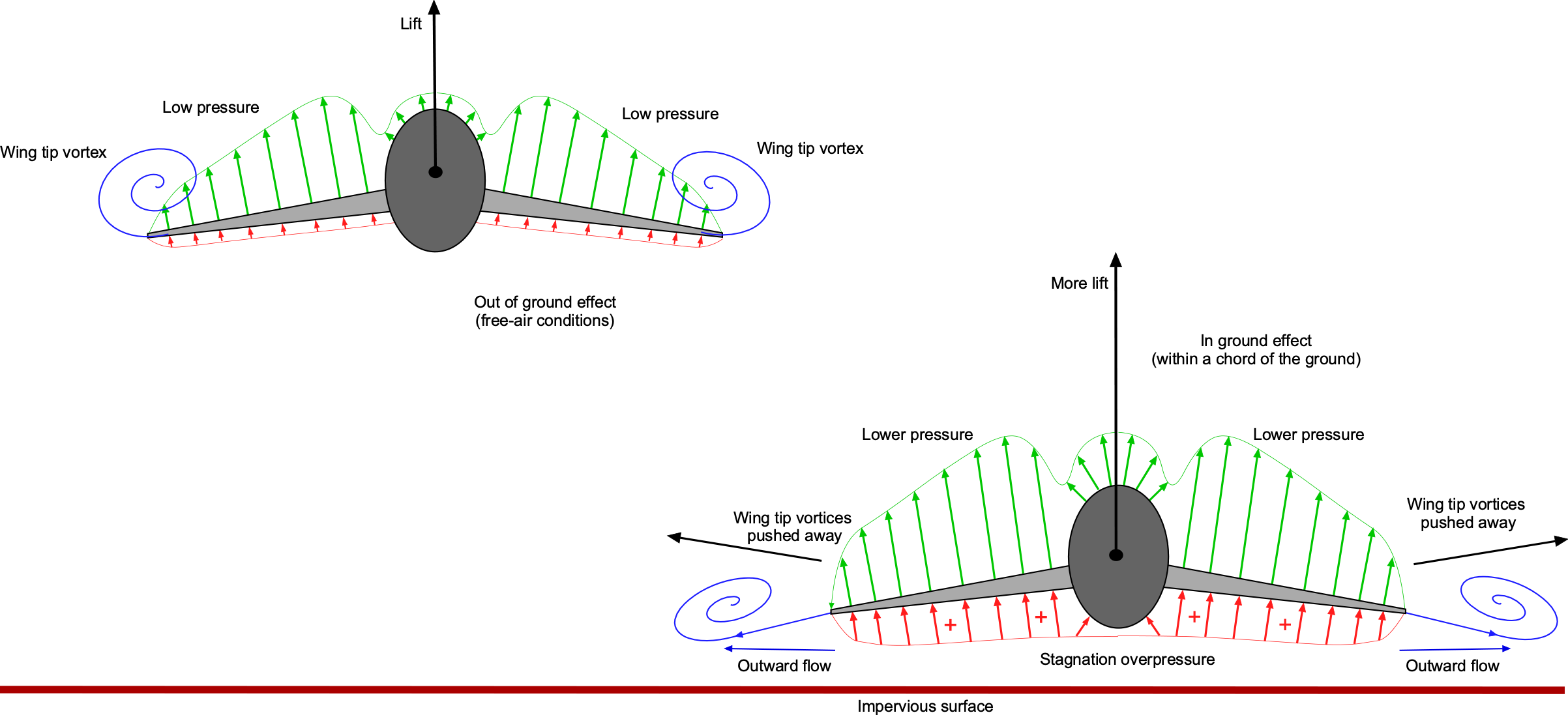
Wing Aspect Ratio Effect
The aspect ratio effect for a wing operating in ground effect pertains to the increase in the effective aspect ratio of the wing by the presence of the ground. Wings with higher aspect ratios (longer and narrower) generally experience less induced drag and are more efficient. Wings with lower aspect ratios can experience a more significant improvement in lift and ground effect efficiency than wings with higher aspect ratios. However, the effects are pronounced for wings of all aspect ratios. The basic principle is illustrated in the figure below, where the ground or other impervious surface causes a lateral outward movement of the wing tip vortices, increasing the effective aspect ratio of the wing.
The induced drag on a wing near a surface can be approximated by the equation
(42) 
One equation to account for the benefits of the surface proximity is the aspect ratio correction factor or “ factor” as given by
(43) 
where  is the height-to-span ratio of the wing above the surface. Notice that
  as increases, so the effects are only significant when the wing operates within one wing span. Therefore, the effective aspect ratio of the wing increases in proximity to the surface, as given by
(44) 
Another approximation for the correction factor is that
(45) 
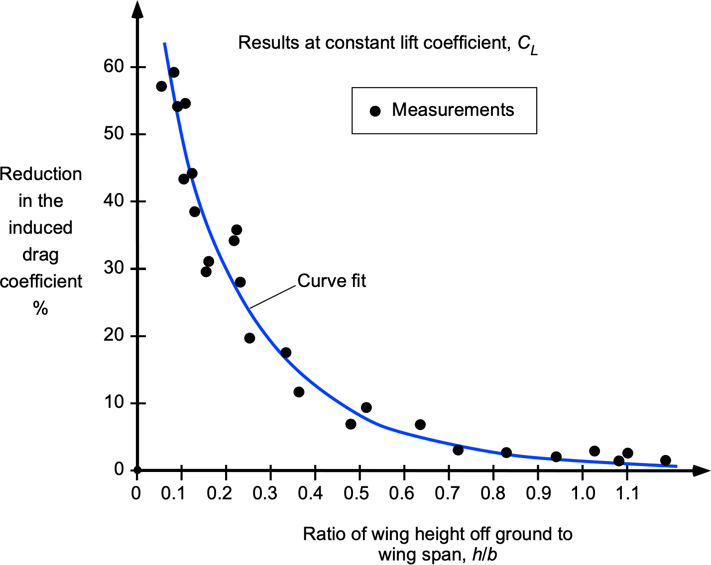
where  is the distance between the trailing edge of the wing and the surface. These simple models are confirmed by the results below, obtained with wings in wind tunnels, suggesting that surface effects can be considered negligible for more than one wing span above the ground.
Thrust & Power Requirements
The drag build-up for a WIGE vehicle follows the same principles as those for an airplane when in flight, although hydrodynamic effects must also be considered until the point of takeoff. Hydrodynamic effects associated with wave-making drag are dominant at low speeds and reach a maximum at the “hump” speed. A significant thrust is required to exceed this speed and get “on the step,” but the net drag on the vehicle decreases markedly when it becomes airborne, as summarized in the figure below. The initial aerodynamic drag remains relatively high from induced losses, but quickly reduces to a minimum as the airspeed increases. The drag then builds as the airspeed increases, and the vehicle eventually reaches its maximum speed, where drag equals the available thrust.
For steady-level flight where thrust equals drag, then
(46) 
The coefficient  is given by
(47) 
where  is the wing’s aspect ratio and is Oswald’s efficiency factor. Because in steady flight
  then
then
(48) 
where  is the air density in which the aircraft is flying,
  is the reference wing area, and
  is the total wing lift coefficient (the assumption here is that the wings generate all of the lift). Notice that
  where the value of
  comes from the ISA model, i.e.,
(49) 
Rearranging this equation, the lift coefficient that needs to be produced on the wing for a given flight speed can be solved for, i.e.,
(50) 
Therefore, the drag becomes
(51) 
and where the corresponding power required, , is given by
(52) 
The first term in this latter equation (the profile or zero-lift power) becomes dominant at higher airspeeds, and the second (induced power) becomes more prominent at lower airspeeds. Of course, the exact quantitative relationships between power and airspeed depend on the detailed aerodynamics of the vehicle, the characteristics of the engines, and overall propulsive and aerodynamic efficiencies. Treating all of a WIGE vehicle’s intricacies must be considered beyond the scope of this introductory exposition.
Limitations of WIGE Vehicles
Several significant limitations of WIGE vehicles must be noted, as is the case with all GEVs. They are specifically designed to operate within half a wingspan above the surface, where the ground effect is most pronounced. Beyond this height, the ground effect quickly diminishes, and the vehicle’s efficiency decreases significantly. This issue can also limit the operational flexibility of WIGE vehicles compared to conventional airplanes, as they cannot use airport runways.
Indeed, WIGE vehicles need large bodies of water or flat surfaces for takeoff and landing, further restricting their operational envelope and increasing vulnerability to weather conditions such as strong winds and high waves. High sea states, characterized by water spray and large waves, can impose significant loads on the wings and fuselage structure. These loads can manifest as structural limitations during take-off and landing in the same manner as a hovercraft. Large quantities of water ingested into the engines can also cause surging and significantly increase the risk of power loss. Despite these limitations, WIGE vehicles can be viable for maritime surveillance, coastal patrol, and high-speed transportation over limited ranges.
Summary & Closure
Ground Effect (Air) Vehicles (GEVs) offer several operational advancements and potential enhancements to the aviation spectrum. The hovercraft, a type of GEV, continues to offer possibilities for various civil and military applications. The elementary theories and methods discussed in this chapter provide the needed equations to help size hovercraft concepts. Specifically, the results have been derived to relate the fan power to the increase in static pressure to overcome the weight of a hovercraft and raise it to some specified hovering height. The methods can also be used to size the propulsion system. The technical aspects of future hovercraft designs dictate a good balance between aerodynamics, hydrodynamics, and innovative engineering. Despite their versatility, further developments in hovercraft technology are necessary and will leverage ongoing innovations in materials, electric propulsion, and other aerospace technologies. Some future hovercraft designs may incorporate hybrid electric and combustion propulsion systems, paralleling developments in the aviation field.
In recent years, there has been a resurgence of interest in WIGE vehicles, and renewed technical efforts aim to explore further their potential for civilian and military purposes, including transport and maritime patrol. Despite the promising aspects, challenges such as regulatory hurdles and safety concerns continue to temper the adoption of such vehicles for civil use. Nevertheless, ongoing developments suggest that the technology behind WIGE vehicles still has much to offer, with potential applications for the future. However, the enormous technical and financial investments required to realize WIGE vehicles mean they may not materialize soon for military or commercial purposes.
5-Question Self-Assessment Quickquiz
For Further Thought or Discussion
- Explain the main components of a hovercraft and how they contribute to its operation.
- What are the two main principles of lift generation in a hovercraft?
- Discuss the advantages and disadvantages of using a skirt system in hovercraft design.
- Describe the challenges involved in maneuvering and controlling a hovercraft.
- How do hovercraft handle different surface conditions, such as rough water or uneven terrain?
- Explain the advantages of hovercraft compared to boats and terrestrial vehicles, such as for search and rescue and military operations.
- Regarding the aviation and maritime spectrum, what might be the advantages and limitations of using WIGE vehicles compared to traditional aircraft and boats?
- Discuss the challenges of controlling and maneuvering WIG vehicles during takeoffs, turns, and landings.
- Explain the potential role of WIG vehicles for maritime patrol, coastal surveillance, and transportation.
Other Useful Online Resources
For additional resources on ground effect vehicles, follow up on some of these online resources:
- Find out more about hovercraft at the Hovercraft Museum.
- What happened to the giant hovercraft?
- Hovercraft – The ultimate frictionless amphibious machine.
- The Top 15 Awesome Hovercraft.
- SRN4 Hovercraft: UK British Transport History. Video
- A UK passenger hovercraft from Calais, France, to Dover, England. Hoverspeed.
- Why most hovercraft have disappeared. Video.
- U.S. Navy’s amphibious hovercraft LCAC. Video.
- This vehicle looks like an airplane, has a car’s engine, and docks like a boat. Video.
