Airships, balloons, and blimps generate buoyancy lift, also known as aerostatic lift, by using an envelope filled with a less dense gas than air, such as helium. This enables them to fly freely and “float” without requiring forward airspeed. Such aircraft have been collectively referred to as “airships” or “aerostats.” Today, they are more usually referred to as “Lighter-Than-Air” or LTA aircraft, a selection of such vehicles being shown in the figure below. Furthermore, because an LTA aircraft does not require a large runway, albeit still needing a relatively large terrestrial footprint for takeoff and landing, it can also be classified as a form of vertical/short take-off and landing (V/STOL) aircraft. Technically, any unpowered and free-floating type of LTA aircraft is considered a balloon, and one that is powered and steerable is called an airship.
There are diverse types of Lighter-Than-Air (LTA) in the aviation spectrum. Unpowered LTA aircraft are considered balloons, while powered, steerable LTA aircraft are referred to as airships.
Historically, airships have suffered from a public perception as lumbering giants of the sky, accompanied by a poor safety record. However, airships and aerostats have been successfully utilized for over a century in various applications, including military surveillance, anti-submarine warfare, border patrol, passenger and cargo transport, and advertising. The most famous are the giant Zeppelin airships and the Goodyear blimps. During the 1920s and 1930s, several Zeppelin airships were used to transport passengers across the oceans and around the world in luxury, a feat not matched by airplanes of that era. However, airships obtained a poor reputation for safety after the Hindenburg erupted in a massive fireball[1] and was destroyed in 1937, in full view of the world’s media, after a successful flight carrying passengers across the Atlantic.
While airships have seen minimal practical use since the 1940s, technological advancements, growing concerns about environmental pollution from conventional airplanes, and a global focus on sustainable transportation have sparked renewed interest in airships. Much of the engineering knowledge about airships dates back over a century, and most technical data reports from the NPL/RAE research labs in Britain and NACA in the U.S. date to the 1920s and 1930s, including extensive wind tunnel tests. However, aerospace engineers must still be aware of the history of airships, including their successes and failures, their operational principles, and their general performance characteristics. Furthermore, engineers must be able to objectively and confidently assess the potential future of airships within the aviation spectrum.
Modern airships are giant aircraft by any standard, dwarfing the A380 and Boeing 747 (even the Hindenburg was three times longer and twice as tall as a 747). They can carry substantial payloads up to 100,000 kg (220,000 lb) over thousands of miles, albeit at relatively low airspeeds, while producing low carbon emissions. Several companies, including Lockheed Martin, Hybrid Air Vehicles, Aeroscraft, and LTH, have been actively involved in airship research and development.
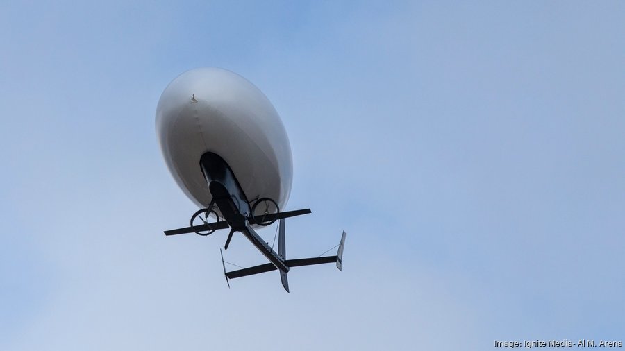
In particular, hybrid airships have garnered considerable attention in recent years, as exemplified by the photograph below. This variation features a cambered tri-hull shape, with disk-shaped cushions on the underside serving as the undercarriage. Hybrids generate both aerostatic (buoyancy) lift and aerodynamic (motion) lift, offering several advantages over traditional airships.[2] regarding performance, payload, and cruise speed. Modern airships have also leveraged advanced aviation safety features, including multiple redundant fly-by-wire flight control systems, active health monitoring, and sophisticated avionics and navigation systems.
The Lockheed Martin P-791 is an experimental hybrid airship that generates both aerostatic and aerodynamic lift.
Modern airships could also incorporate advanced propulsion systems, such as hybrid electric, hydrogen fuel cell, or solar energy technologies. This type of propulsion gives excellent efficiency, lower energy costs, and a smaller carbon footprint.[3] As climate change and sustainability concerns continue to increase, airships may soon find a new niche in aviation, perhaps with them servicing an Amazon or Walmart distribution center near you! While airships fly relatively slowly compared to airplanes, their cruise speeds are still much faster than seaships and as fast as any terrestrial vehicle or truck. They also have the advantage of flying directly from one place to another over land or sea.
However, the future implementation and widespread adoption of new generations of airships will still depend on many interrelated factors, including further technological advancements, regulatory considerations, public perception, economic viability, the broader availability of hangarage and maintenance facilities, and the ability to operate in all weather conditions. Indeed, while the future of airships shows much technical promise, it remains to be seen how (or if) such aircraft can mature to become an important and viable economic part of the future commercial aviation spectrum.
Learning Objectives
Know about the history of balloons, airships, and other aerostats.
Understand the principles of buoyancy and aerostatic lift.
Appreciate the aerodynamic performance characteristics of airships.
Understand how an airship is controlled during flight using buoyancy and propulsion.
Be aware of airships’ stability, handling qualities, and unique flight characteristics.
History
The first LTA aircraft was a hot-air balloon, which was also the first human-carrying flight vehicle capable of sustained flight. It was designed in France by the Montgolfier brothers in 1783. Their balloon, made of paper and silk, rose to an altitude of about 2,000 m (6,560 ft) without a pilot. A few weeks later, a larger balloon, the Aerostat Reveillon, was launched carrying pilot Jean-François Pilâtre De Rozier, who ascended to the end of its 90 m (295 ft) rope tether. A month later, De Rozier and the Marquis d’Arlandes made aviation history by conducting the first free flight in a balloon, which ascended to around 150 m (492 ft) and drifted approximately 8 km (5.5 miles) before safely landing.
An artist’s sketch of the first free flight of a Montgolfier hot air balloon circa 1783.
Benjamin Franklin, who served on a diplomatic commission to France from 1776 to 1778, witnessed some of these early balloon flights. He was so impressed that he predicted that balloons would soon have considerable military value for “conveying intelligence into, or out of, a besieged town, giving signals to distant places, or the like.” Indeed, tethered balloons were to be used during the American Civil War for battlefield surveillance. They could reach altitudes of up to 300 m (984 ft), giving a great vantage point for soldiers, who used signal flags to send information down to their commanders.
For the next 150 years, hot-air balloons saw limited interest and were surpassed by airships and many other forms of aircraft. However, in the 1960s, hot-air ballooning became a popular recreational activity and a competitive sport. In 1987, Richard Branson and Per Lindstrand became the first to cross the Atlantic in a hot air balloon, flying 2,900 miles (4,670 km) in 33 hours. Branson and Lindstrand paired up again in 1991 and were the first to cross the Pacific in a hot air balloon. They traveled 6,700 miles (10,800 km) in 47 hours from Japan to Canada, breaking the world distance record by traveling in the high-altitude jet stream. Four years later, Steve Fossett became the first to complete the Transpacific balloon route as a solo pilot, riding the winds and the jetstream for four days while traveling from South Korea to Canada.
The need for balloons that could be combined with propulsion led to the development of airships with rigid internal structures known as dirigibles. The first dirigible was built and flown in 1852 by Henri Giffard, who used a steam engine driving a propeller. Today, an airship is typically defined as any powered, steerable aircraft that is inflated with a lighter-than-air gas. Early airships were filled with hydrogen gas, which is highly reactive and can be spontaneously explosive. Several airships had caught fire even before the infamous Hindenburg disaster in 1937. Using inert helium rather than explosive hydrogen as the buoyant gas would have prevented the Hindenburg from catching fire.[4]
The LZ127 Graf Zeppelin, as depicted in the photograph below, was a German airship filled with hydrogen, the buoyant gas that enabled the first successful transatlantic passenger flight in 1928. It flew from Friedrichshafen, Germany, to Lakehurst, New Jersey, in the U.S., covering approximately 3,000 miles (4,800 km) in 112 hours. This impressive achievement was a milestone in the history of airship travel. It demonstrated the feasibility of long-distance passenger-carrying airship flights in relative comfort compared to airplanes of that era. In 1928, travelers could still travel faster by train than by airplane, such as the Ford Trimotor, which was also so noisy that passengers had to stuff cotton wool in their ears.
The “Graf Zeppelin” photographed landing in Berlin, Germany, circa 1931.
The British, as did the U.S., soon developed airships derived from German designs. The R100 and its sister ship, R101, were built in 1922 as part of a British government initiative to establish airships to transport passengers and mail from Britain to the most distant parts of the British Empire, including India, Australia, and Canada. The R100, which used hydrogen as the buoyant gas, first flew in December 1929 and made a well-publicized return crossing of the Atlantic to Canada in the summer of 1930. But following the demise of the R101, it was scrapped. While other British airships were built through to the end of 1930, they were largely unsuccessful. The U.S.S. Macon, as shown in the photograph below, and the U.S.S. Akron were among the largest airships ever built. Although the hydrogen-filled, Zeppelin-built LZ 129 Hindenburg and the LZ 130 Graf Zeppelin II were longer, these two U.S. Navy airships were the most voluminous helium-filled dirigibles. Unfortunately, both U.S. airships were destroyed in the mid-1930s, further diminishing the operational and safety reputation of airships.
The U.S. Navy airship USS Macon, photographed flying over New York City in 1933. Airships made in the United States used helium as the buoyant gas.
A blimp, essentially a “pressure airship,” maintains its shape through the gas pressure inside the envelope. Unlike a dirigible, which has a structural skeleton, a blimp loses its shape when the internal pressure is reduced. The B-class blimps, as shown in the photograph below, were patrol airships operated by the U.S. Navy during and shortly after WWI and used with much success for convoy and antisubmarine patrol duties. The design of the B-class blimps allowed them to operate effectively over coastal waters, providing a vital service in detecting and deterring submarine threats during a critical period in naval warfare.
The U.S. Navy operated the B-1 airship during WWI. The B-1 had dual lower fins, and later B-types had only one fin.
In 1925, Goodyear Tire & Rubber Company began building blimps. These aircraft were initially used for advertising purposes, but later proved valuable for numerous military applications during various campaigns throughout WWII. Goodyear’s blimps proved a valuable asset to the Navy because they could stay airborne for long periods without using much fuel. Newer versions of blimps have a minimal internal structure made of lightweight composite materials such as carbon fiber, classifying them as semi-rigid airships.
Tethered aerostats have offered a unique and valuable solution for specific applications that require a stable, long-duration aerial platform. The tethered design provides advantages in terms of stability, cost-effectiveness, and prolonged observation capabilities. Their wartime use dates back two centuries to gather intelligence, observe enemy activities, and direct artillery fire. A form of aerostat called a barrage balloon proved an effective defensive measure for the British during WWI and WWII; see the photograph below. They disrupted enemy flights, forced aircraft to fly at higher altitudes, and provided early warning by visually alerting ground forces of incoming aircraft. Aerostats, in the form of blimps, are still used today by the Tethered Aerostat Radar System (TARS) to monitor the southern U.S. border; each aerostat is moored to the ground with a cable, and its altitude can be raised and lowered using a winch.
Barrage balloons at Omaha Beach in France during the early days of the Allied invasion of Europe in June 1944.
Anatomy of LTA Aircraft
LTA aircraft comprise various types of balloons, airships, and other aerostats. As aeronautical technology evolved, the name “balloon” has become reserved for hot air balloons, which are recreational aircraft. While the name “aerostat” still encompasses most types of LTA aircraft, an aerostat is usually considered an unpiloted LTA aircraft tethered to the ground with a cable. The name “airship” is reserved for a piloted lighter-than-air (LTA) vehicle with a propulsion system, enabling the aircraft to fly from one location to another while carrying a payload or performing a useful task.
Balloons (Thermal Aerostats)
A balloon or thermal aerostat is the simplest form of unpowered aerostat. Because balloons have limited control capability and drift freely in the winds, they are generally flown in light winds and good weather. Notable uses of balloons in modern aviation include weather balloons for meteorology (typically filled with helium) and sporting “hot-air” balloons for recreation, as shown in the figure below.
Balloon types of aerostats have become synonymous with the numerous colorful hot-air balloons used for recreation.
Hot air balloons have a propane burner to heat the air inside the envelope. As the air heats up, it becomes less dense than the surrounding cooler air, causing the balloon envelope to inflate and creating a buoyancy force. There is little difference in the density of hot and cold air, so the envelope must be voluminous to lift even a couple of people. Hot air balloons typically carry ballast, usually in the form of sandbags, which can be dropped or emptied to reduce weight. The pilot can open a parachute valve by pulling down on a cord to let some hot air escape, thereby controlling the balloon’s altitude and achieving neutral buoyancy. Those who have flown in hot air balloons generally say it was a serene and picturesque experience, the uncertainty of the landing point being part of the excitement of this type of aerial adventure.
Stratospheric Balloons
There are also balloons designed for flight in the upper stratosphere and at the edge of space, as shown in the figure below. They typically fall into two main types: zero-pressure and super-pressure balloons. Both of these types utilize helium gas for buoyancy. They are the only type of flight vehicle that can be operated in this region of the atmosphere, which ranges from 50,000 ft to 150,000 ft (approximately 15 km to 45 km) in altitude, a height too low for satellites and too high for airplanes. The payload gondolas can carry experiments in science, astronomy, atmospheric chemistry, and weather. At the end of the mission, the payload is severed from the balloon and recovered by parachute.
Stratosphere balloons utilize helium gas for aerostatic lift.
Zero-pressure stratospheric balloons have release valves that allow the pressure inside the balloon to equal that of the outside. These balloons will continue to rise until they find a buoyancy altitude or burst; potentially, they can stay aloft for weeks or months. Super-pressure balloons are entirely sealed and maintain a higher pressure inside, allowing them to maintain their operational altitude despite temperature changes that occur day and night. Super-pressure balloons are launched partially filled with helium. As the balloon ascends and ambient air pressure decreases, the helium expands to fill the envelope, allowing it to reach its desired float altitude.
Dirigibles
Airships (dirigibles and blimps) are traditionally piloted and use engines driving propellers or fans for forward propulsion. Depending on their structural design, airships are divided into three types: rigid, semi-rigid, or blimp (pressure airship). Semi-rigid airships usually fall into the blimp class. The classic rigid airship, a dirigible, has an internal space-frame structure surrounding its gas containers (gasbags), as shown in the figure below.
A dirigible is a classic rigid airship featuring an internal space-frame structure that surrounds its gas containers.
The Zeppelins of the 1920s through the 1940s are well-known examples of dirigibles, which used hydrogen as the buoyant gas; the airships in the U.S. used helium. The main structure is usually aluminum, but more modern dirigibles are more likely to use composites. The internal structure provides the shape and rigidity of the airship, while the outer covering, or envelope, remains unpressurized. The covering must be a strong and durable fabric, but it does not have to be gas-tight like a blimp because the buoyant gas inside a dirigible is contained in a series of separate gas bags.
The gondola, or car, is the compartment suspended below the envelope, where passengers, crew, and other equipment are housed. The integral internal structure connects the gondola, empennage, engines, and gas cells, carrying and distributing the loads across the entire structure. The engines may be located on the gondola, but because of a dirigible’s expansive, rigid internal structure, there are multiple hard points, allowing the engines to be placed almost anywhere. The vertical stabilizer, or fin, helps maintain the aircraft’s directional stability, and the horizontal stabilizer gives pitch stability. Airships utilize various control surfaces to help maneuver, including rudders and elevators, which are used for yaw and pitch control, respectively.
Blimps
A non-rigid airship, also known as a blimp, maintains its shape from the pressure of the buoyant gas within it. Blimps may have some external bracing or reinforcement to support the weight of the gondola and engines. However, in the classic blimp, the gondola is suspended from the top of the envelope by a catenary curtain (like a hanging chain) with attached cables, as shown in the figure below; these cables are internal to the gas envelope. Buoyancy is controlled using air-filled ballonets that allow the center of buoyancy to be modified for control and trim. The iconic Goodyear GZ20A blimps were used until 2017. The new semi-rigid Goodyear Zeppelin NT blimps, which have an internal structure, are extensively used in the U.S., especially at major sporting events such as the Super Bowl and the Daytona 500.
Anatomy of an airship in the form of a classic blimp.
Semi-Rigid Airships
The modern version of the Goodyear blimp, as shown in the figure below, is a semi-rigid blimp (Zeppelin NT), which can be noted by the absence of internal suspension cables holding the gondola. This airship uses helium as the buoyant gas, a modern successor of the classic Zeppelin dirigibles of the 1930s. Semi-rigid airships have an internal structure that supports the gas envelope and other components, such as gondolas, engines, and tail surfaces. However, the envelope maintains its shape using the internal pressure of the helium, so semi-rigid airships still fall into the blimp class. The engines drive propellers or ducted fans to provide the thrust necessary to propel the airship forward or backward, and vectoring the thrust can significantly help maneuverability. Modern airships use water ballast rather than lead shot; however, the features of semi-rigid airships (Goodyear still refers to them as blimps) are similar to those of dirigibles.
Anatomy of an airship in the form of a semi-rigid blimp. The photograph is of a Zeppelin NT, a new class of helium-filled airships.
Tethered Aerostats
A tethered aerostat is anchored to the ground by a cable; in the photo below, it is tethered to its mooring point. Letting out the cable allows the aerostat to rise and be tethered at various altitudes. A ballonet is used to control the buoyancy. Such aerostats have been employed for persistent aerial surveillance over a designated area. Equipped with multiple sensors, cameras, and radar systems, aerostats can monitor troop movements, detect threats, and provide real-time intelligence. Tethered aerostats are also utilized for telecommunications purposes. Lifting communication equipment, such as antennas and repeaters, to high altitudes can enhance wireless communication networks over a wide area. This technology is particularly useful in remote areas where traditional communication infrastructure is limited or damaged. A typical system consists of a tethered aerostat capable of providing radar surveillance and high-resolution imagery over a large area from an altitude of only a few thousand feet.
Anatomy of a tethered aerostat. While relatively simple, they can carry a variety of sophisticated radars, cameras, and sensors.
Hybrid Airships
Hybrid airships are designed to combine features of airplanes and airships. As shown in the figure below, these innovative vehicles carry a fraction of their weight because of buoyancy, and the remainder is supported by aerodynamic lift generated by their airframe shape. Their aerodynamic lift production may be as high as 30% of their weight.
Hybrid airships combine features of traditional airplanes and airships to obtain higher efficiency and a wider operating envelope.
Hybrid airships are designed to bridge the gap between the low operating costs and low airspeeds of traditional airships and the higher speeds but higher fuel consumption of airplanes. By combining dynamic and buoyant lift, hybrids can cruise at higher airspeeds with a greater payload compared to a pure airship. Because of their large size, they have a significantly higher payload capacity compared to other aircraft types. This makes them suitable for various applications, including cargo transportation, disaster relief efforts, and remote access operations. However, they do need ample hangar space for maintenance and storage, which is also a consideration of where and when they can operate.
Led Zeppelin – Going Down Like a Lead Balloon!
Led Zeppelin is one of the most famous rock bands of all time. They recorded nine albums between 1968 and 1979, selling over 300 million copies. The name “Led Zeppelin” stemmed from a humorous conversation in 1967 among several musicians about the new band’s chances of flopping, i.e., going down like a lead balloon. Their lead guitarist, Jimmy Page, then came up with the name “Led Zeppelin,” and everything else is now history.
Buoyant (Lifting) Gases
A buoyant gas or lifting gas is any gas that produces buoyancy or aerostatic lift, so this gas must be less dense than the surrounding air. Well-known buoyant gases include hydrogen, helium, and hot air. The choice of buoyant gas depends on availability, cost, and safety. Helium is the most suitable for airship and aerostat operations because it is non-flammable and non-toxic. However, helium is relatively expensive,[5] and supplies can be intermittent. Hot air, as a buoyant gas, is typically used in recreational balloons.
Hydrogen
Hydrogen (H2) is the lightest and most buoyant lifting gas, with a molecular weight of 2. Hydrogen is the lightest and most buoyant lifting gas, with a molecular weight of 2.016. It has a low density and provides maximum aerostatic lift per unit volume, often referred to as lifting capacity. It is readily available and relatively inexpensive. However, hydrogen is highly reactive and potentially explosive, posing safety risks. Many hydrogen-filled airships were lost in the 1920s because of fire and explosion, and the use of hydrogen decreased significantly after the Hindenburg disaster in 1937. Aviation regulators currently ban the use of hydrogen for airships, but this position may change if hydrogen is ultimately approved for use as a fuel on airplanes.
Helium
Helium (He) is the second lightest gas, with a molecular weight of 4.003. Helium is non-flammable and safer than hydrogen. Helium is not reactive and does not support combustion. It is commonly used in modern airships and some types of balloons. Helium is extracted from underground gas pockets as a by-product of natural gas refinement. It is a relatively rare gas and expensive, especially at the volumes needed for an airship. Helium is a commodity, and its price varies daily. But filling a Goodyear blimp with helium would cost about $100,000 versus $15,000 for hydrogen.
Ammonia
Ammonia (NH3) is lighter than air, but with an atomic weight of 17.02, it is considerably heavier than hydrogen or helium. It has a good lifting capacity, but it is a pungent, choking gas that is toxic and corrosive. However, ammonia is less flammable than hydrogen. It was used in some early airships before the availability of hydrogen and helium in the quantities needed. Because ammonia is highly toxic, its release into the atmosphere poses numerous environmental hazards, and its use for LTA aircraft has been permanently discontinued.
Hot Air
Hot air is produced by heating ambient air using propane burners. Air has a molecular weight of about 29. Hot air is less dense than the surrounding air, creating buoyancy. It does not pose the safety concerns associated with hydrogen. Hot air has a much lower lifting capacity than gases like hydrogen or helium, so a greater volume is required to produce buoyancy. Balloons using hot air require almost constant heating to maintain buoyancy because of rapid heat transfer through the thin gas envelope.
Summary of Buoyant Gases
The table below summarizes the essential properties of buoyant gases, with air as the reference. The density values are given in grams per liter (g/L) at standard temperature and pressure (STP), which has the same numerical value in units of kilograms per cubic meter (kg/m3). While hot air is easy and inexpensive to produce, it has limited lifting capacity, so the gas envelope needs to be very large and voluminous.
Property
Hydrogen
Helium
Ammonia
Hot Air
Air (reference)
Chemical Formula
H₂
He
NH₃
N2 + O2 + mixture of other gases
N2 + O2 + mixture of other gases
Density
0.08988 g/L (STP)
0.1786 g/L (STP)
0.769 g/L (STP)
1.14 g/L (30oC) Varies based on temperature
1.225 g/L (STP) Varies based on temperature
Color
Colorless
Colorless
Colorless
Colorless
Colorless
Odor
Odorless
Odorless
Pungent
Odorless
Odorless
Flammability
High
None
None
None
None
Where does helium come from?
Helium is a naturally occurring element in the Earth’s atmosphere, but its concentration is too low for economical extraction. Helium is also found in underground gas deposits, which migrates upward to the top of the gas pocket because of its low density. The helium that accumulates can then be separated and collected for use. The U.S. is the world’s largest helium producer; the sole source of helium in the U.S. comes from a plant operated by the Bureau of Mines & Land Management in Texas. However, helium is a finite resource, and its annual and long-term availability is unpredictable. Consequently, recent efforts have been made to promote the conservation and responsible use of helium. Ironically, modern airships may revert to using hydrogen if helium sources are limited or it becomes cost-prohibitive.
Why Not a Vacuum Airship?
Theoretically, a vacuum airship could provide the highest possible buoyancy because a perfect vacuum is lighter than any gas. However, the required structural integrity of such an airship presents a fundamental challenge. At sea level, atmospheric pressure exerts 101.3 kPa (14.7 psi), meaning any envelope containing a vacuum must resist large external forces. Most lightweight materials would collapse or implode under this pressure unless they were extremely strong and rigid, adding significant structural weight. Even advanced materials like carbon fiber composites are currently too heavy relative to their strength to make such a structure viable. To achieve lift, the envelope must be both strong enough to resist collapse and light enough to weigh less than the air it displaces.
In addition, the lift advantage of a vacuum over helium is relatively small. While a perfect vacuum displaces a mass of 1.225 kg of air per cubic meter, helium provides nearly the same effect, displacing 1.11 kg/m, giving only about 16% less buoyancy. This marginal gain does not justify the engineering difficulties involved in constructing a vacuum airship. Helium and hydrogen-filled airships, which are far easier to build and maintain, already achieve near-optimal buoyancy without the structural challenges posed by vacuum containment.
Principle of Buoyancy
Archimedes’ principle is used to analyze the aerostatic forces on LTA aircraft. This principle states that the upward or buoyancy force exerted on a body immersed in a fluid equals the weight of the fluid that the body displaces. This behavior is true whether the body is wholly or partially submerged in the fluid and is independent of the body’s shape. As shown in the figure below, the resulting force acts upward at the center of buoyancy of the displaced fluid (which is also the center of mass). This principle is commonly used in problems involving the hydrostatic or aerostatic analysis of all “floating bodies,” such as boats, ships, balloons, and airships.
Archimedes’ principle states that the upthrust or buoyancy force on a body immersed in a fluid equals the weight of the displaced fluid.
To better illustrate the concept of buoyancy, consider the scenarios shown in the figure below. The object’s volume is the same in each case, but its weight differs, ranging from (the heaviest) to (the lightest). If the object is entirely immersed in the fluid, then the buoyancy force, , will be
(1)
where is the volume of the object and hence the volume of the displaced fluid, and is the density of the displaced fluid. The buoyancy force only depends on the weight of the fluid displaced by the object, not the weight of the object. However, the net force on the object is a balance between the buoyancy and the weight, i.e.,
(2)
where is the density of the object.
The buoyancy force on an immersed object depends on the weight of the fluid displaced by the object, not the object’s weight.
Now consider a hot-air balloon floating in the atmosphere, as shown in the figure below. The balloon’s envelope contains hot (i.e., warmer) air so that it will have a lower density than the surrounding cooler air. Using Archimedes’ principle, the balloon’s buoyancy force will equal the weight of the displaced colder air. The balloon’s net weight will include the weight of its envelope and structure (including any items in the basket hanging below) plus the weight of the hot air. Therefore, the net force acting on the balloon will equal the difference between the balloon’s net weight and the weight of the displaced air.
In aerostatic equilibrium, the upthrust on a balloon will equal its weight. Its center of gravity lies well below the center of buoyancy, giving it high pendular stability to external disturbances
For neutral buoyancy, the weight of hot air inside the balloon, , plus the weight of the balloon itself, , equals the buoyancy lift, , or upthrust , i.e.,
(3)
The buoyancy lift is given by
(4)
where is the volume of the balloon’s envelope. The weight of the hot air will be
(5)
Therefore, for neutral buoyancy, then
(6)
Check Your Understanding #1 – Buoyancy of a hot-air balloon
A hot air balloon becomes neutrally buoyant at an altitude of 1,100 m where the outside air temperature is 10.5C. With all its cargo, the balloon has a mass of 500 kg (excluding the air in the balloon), displacing a volume of 7,000 m3. Assume that the pressure inside the balloon is equal to the pressure outside. Determine the air temperature inside the balloon to give it neutral buoyancy. At 1,100 m, the air density can be considered 1.102 kg/m3.
Show solution/hide solution.
For neutral buoyancy, the weight of hot air inside the balloon + the weight of the balloon itself = the lift or upthrust (according to Archimedes’ Principle) caused by the weight of displaced cool air, i.e., there is no net vertical force on the balloon so that
The air volume displaced by the balloon is = 7,000 m. Therefore, the weight of cool air displaced by the balloon is then.
which is equal to the upward buoyancy force according to Archimedes’ Principle. The mass of the balloon is 500 kg, so its weight, , is 500 = 500 9.81 = 4905.0 N. Notice that is the density of the displaced air at a height of 1,100 m, which is given as 1.102 kg m.
Therefore, for neutral buoyancy (i.e., if the net vertical force is zero), the weight of the hot air in the balloon must be
This means that the corresponding density of the hot air inside the balloon must be
which is less than the density of the surrounding cool air, as expected.
We are asked to determine the corresponding temperature of the hot air, for which we can use the equation of state, i.e.,
We are told to assume that the pressure inside the balloon is the same as that outside the balloon, so
Rearranging gives the ratio of the temperatures as
The outside air temperature at 1,100 m is 10.5 C or 283.65K. Therefore, the temperature of the hot air needed for neutral buoyancy will be
Therefore, a differential internal temperature of approximately 20C is observed at these altitudes and temperature conditions.
Geometric Characteristics of Aerostats
Traditionally, airships and many aerostats have streamlined hull shapes based on prolate spheroids, i.e., those that look like fat cigars; spheres closely approximate balloons. An ellipsoid, shown in the figure below, is the most general shape in this geometric class of bodies of revolution that includes, in special cases, prolate and oblate spheroids, as well as spheres.
An ellipsoid is a general class of geometric shapes that includes prolate and oblate spheroids and spheres.
Regarding aerodynamics and other characteristics of such shapes, the key geometric parameters of interest are the ellipsoid’s projected frontal area, volume, surface area, and slenderness ratio. Aerodynamic coefficients used in the analysis may be based on any or all of these parameters. Therefore, it is essential to understand how they are defined.
Projected Frontal Area
The projected frontal area, , of a general ellipsoid is
(7)
In the case of a prolate spheroid where , or a sphere where then
(8)
Volume
The general formula for the volume of an ellipsoid is
(9)
Notice that when , then this formula is the volume of a sphere, i.e.,
(10)
The formula for the volume of a prolate spheroid with and is
(11)
Surface Area
The surface area of a spheroid is a surface of rotation, which is given by
(12)
where the eccentricity, of an prolate spheroid is
(13)
For aerodynamic problems, the surface area is called the “wetted area.
In the case of , Eq. 12 becomes infinite. However, if the logarithm term is expanded as a Taylor series, then
(14)
giving
(15)
so for a sphere with and , then
(16)
In general, an approximate formula for the wetted area of a general ellipsoid is
(17)
where = 8/5.
Slenderness Ratio
The aerodynamic characteristics of airships are often expressed in terms of the slenderness ratio. The slenderness ratio, , for an prolate spheroid is defined as
(18)
where is the length and is the maximum diameter.
Definition of the slenderness ratio, , for a prolate spheroid.
The slenderness ratios of a family of prolate spheroids are shown below. Most airships fall in the range 4 < < 6, which, based on historical precedent, has been found to give the lowest average aerodynamic drag.
Examples of the slenderness ratios of a family of prolate spheroids. Airships tend to have values in the range of 4 to 6.
Center of Buoyancy
To understand the flight characteristics of LTA aircraft, it is essential to determine the aerostatic buoyancy force and the center of buoyancy, i.e., the point at which the resulting buoyancy force can be assumed to act. The center of buoyancy, or the center of the aerostatic lift, is also the center of volume and gravity of the displaced air. Therefore, the center of buoyancy can be determined by finding the center of volume of the buoyant gas within the airship’s envelope.
It is useful to first illustrate the process in two dimensions, which means finding the center of area of a slice of a three-dimensional object. In reference to the figure below, the total area can be determined using
(19)
Method of calculating the center of area (center of buoyancy) on a two-dimensional surface.
The first moments of area are given by
(20)
and
(21)
The location (coordinates) of the center of area, , is then determined using
(22)
and
(23)
Naturally, the process can be extended to three dimensions involving volumetric integrals. In practice, an approximate center of buoyancy will be determined numerically because there is unlikely to be an exact formula for an airship’s shape. In this case, the integrals in the equations above will be replaced by numerical summations based on the actual shape of the function. Most CAD software allows for the automatic calculation of the volume and center of volume of a shape.
The concept of the center of buoyancy is important for LTA aircraft.
Aerostatic Trim
In the absence of aerodynamic forces, a stationary free-flying airship or other LTA aircraft will be in static equilibrium when the center of gravity lies directly below the center of buoyancy, as shown in the figure below, i.e., the upthrust from buoyancy equals the weight, as given by
(24)
Notice that the center of gravity for an airship is generally well below the center of buoyancy, which gives the aircraft significant pendular stability about the pitch and roll axes. In aerostatic trim or the static equilibrium condition, most airships are not entirely level but can be seen to take on a slightly nose-high attitude. Airships have very little inherent stability about the yaw axis, although disturbances in yaw are heavily damped by the aerodynamic forces on the fuselage and vertical tail(s).
In aerostatic trim conditions and without any thrust vectoring, the center of gravity of an airship will lie below the center of buoyancy.
The buoyancy force, , or aerostatic lift, , on the airship will be equal to the net weight of the air displaced less the weight of the helium inside the envelope, i.e.,
(25)
where is the volume of the gas envelope, is the density of air, and is the density of helium gas. If the net sum of the structural, fuel, and payload weight of the airship is , then for vertical force equilibrium and neutral buoyancy, then
(26)
Therefore, for a given set of atmospheric conditions, the required volume of helium gas can be determined to provide a specific buoyancy force that overcomes the airship’s weight.
Check Your Understanding #2 – Buoyancy of an airship
An airship has a gas envelope with a volumetric capacity of 296,520 ft³. Helium is used as the buoyant gas. If the airship has an empty weight of 14,188 lb and a maximum fuel load of 960 lb, what would be the maximum payload the airship could carry? Assume MSL ISA standard atmospheric conditions. The density of helium can be assumed to be 0.0003192 slugs/ft3. Ignore the effects of any ballast.
Show solution/hide solution.
The upforce (lift), , on the airship will be equal to the net weight of the air displaced less the net weight of the gas inside the envelope, i.e.,
where is the volume of the gas envelope. The gross weight of the airship will be the sum of the empty weight, , plus the fuel weight, , plus the payload, , i.e.,
For vertical force equilibrium at takeoff, then , so
Rearranging for the payload weight gives
Using the numerical values supplied gives
Therefore, the maximum payload at the takeoff point would be 4,429 lb.
Ballast
Some form of ballast is used on most types of LTA aircraft. Ballast is any material placed on board a buoyant aircraft to add non-structural weight for balance and/or trim. Water ballast, carried internally in tanks, is typically used, although bags containing sand or lead shot can also be used. Besides trim and balance, ballast can be taken on or cast overboard to achieve a particular takeoff or in-flight weight, as well as for landing and unloading the airship on the ground. For example, on a hot air balloon, ballast in the form of sandbags is used to keep it firmly on the ground as the hot air fills up the envelope. Some ballast is dropped overboard when the airship is ready to fly, and the balloon is said to weigh off. During descent, dropping more ballast can reduce the descent rate as the balloon comes in for a landing.
Airships and blimps will also add or remove ballast, such as bags of lead shot, or add or dump water ballast before weigh-off. The weigh-off condition refers to the state in which the airship is trimmed for optimal operation during the initial part of the flight. To this end, ballast is added until the aircraft reaches a point where it becomes slightly heavier than the upward aerostatic buoyancy force, which is called static heaviness.
After takeoff, the pilot first gives the airship a pronounced nose-high attitude using up-elevator so the engines can provide a vertical component of thrust to overcome the static heaviness. If thrust vectoring is available, the propulsion system is swiveled to give mostly vertical thrust during the takeoff maneuver. These actions propel the airship upward and forward into a climb. As the airship gains altitude and airspeed, the airflow over the envelope generates some aerodynamic lift, and the pilot reduces the pitch attitude to reach a steady climb. Finally, the nose is lowered to almost level for the cruise.
It is important to note that “static heaviness” refers to the airship’s weight when stationary. The specific value of static heaviness of an airship can vary greatly depending on its size and configuration. Typically, the static heaviness is between 5% and 10% of the gross weight. Larger airships that carry heavy payloads must have a higher static heaviness than smaller blimps. Hybrid airships have the largest static heaviness because their hull shapes are designed to produce significant aerodynamic lift, so the takeoff and landing will involve a short runway length.
Ballonets
Ballonets (meaning little balloons in French) are the gaseous equivalent of the water ballast tanks used on submarines. They are used in airships and blimps to control buoyancy and the center of buoyancy of the lifting gas. As shown in the figure below, the ballonets consist of internal gas bags or chambers within the airship’s envelope that can be inflated or deflated with air to control the volume of the buoyant gas. Another purpose of the ballonets on blimps is to maintain the buoyant gas’s net positive differential pressure so that the envelope retains its shape.
They are used in airships and blimps to control buoyancy and the center of buoyancy.
Pressurized air is pumped into the ballonets using a system of scoops, electric pumps, ducts, valves, and pressure regulators. The air scoops are often placed where the dynamic pressure from the slipstream created by the propellers or other propulsion systems can be captured. The ballonets are operated through an automatic pressure control system to regulate the inflation and deflation processes, and any excess pressure is released by venting through a set of air valves; pilots can also control the ballonets manually.
Inflation Fraction
Recall that buoyancy or aerostatic lift is equal to the weight of the air that the buoyant gas displaces less the weight of the buoyant gas itself, i.e.,
(27)
where is the volume of the buoyant gas contained in the envelope, is the density of air, and is the density of the buoyant gas, e.g., helium.
The inflation fraction, , is defined as the volume fraction of the total volume of the envelope occupied by the buoyant gas, i.e., the fraction not occupied by the ballonets. If the total volume of the envelope is , then the inflation fraction is
(28)
For example, an inflation fraction of 0.85 would mean that 85% of the envelope’s volume would produce buoyancy. Therefore, the buoyancy can be written in terms of the inflation fraction as
(29)
the concept being shown in the figure below. The ballonets do not produce buoyancy because they are filled with air at nominally ambient conditions, and so act like ballast in the same manner water is used for ballast on a submarine.
The concept of inflation fraction, where only a fraction of the envelope’s volume produces buoyancy.
For a rigid airship or dirigible, the volume is defined as the net volume of the buoyant gas cells; these gas cells do not fill the entire envelope, so the potential lifting capacity is less than the volume enclosed by the envelope. The individual gas cells will also have different volumes because they are distributed along the length of a shape resembling a prolate spheroid. If an individual gas cell of volume, , with cells has an inflation fraction, , then the volume of buoyant gas will be
(30)
The analysis process then proceeds as before.
Controlling Buoyancy
By adjusting the internal air pressure and volume in the ballonets, they will expand or contract, allowing the overall inflation fraction of the airship’s envelope to be modified and thereby controlling the buoyancy and center of buoyancy. Ballonets also provide a means to adjust buoyancy and compensate for changes in atmospheric conditions, such as pressure and temperature, solar heating of the envelope, and weight loss resulting from fuel burn. This process allows the airship to safely ascend or descend, change its pitch attitude, and compensate for variations in the center of gravity location.
For example, as shown in the figure below, the ballonets are initially inflated with air, reducing the volume of the buoyant gas and giving the airship some static heaviness. After weigh-off and the initial climb, the external atmospheric pressure and density decrease, allowing the buoyant gas to expand. Excess air in the ballonets is vented out to maintain a constant differential pressure across the envelope, allowing the buoyant gas to expand freely, thereby keeping the airship’s net buoyancy.
As an airship gains altitude, the pressure in the ballonets is released, allowing their volume to contract.
Pressure Altitude (Gas Ceiling)
The highest achievable altitude, where the gas pressure differential reaches its design limits when the ballonets are mostly fully deflated, is called the “pressure altitude.” However, this airship term should be kept distinct from the pressure altitude used in altimetry; therefore, the condition is best referred to as the gas ceiling. In an emergency, the overpressure of the buoyant gas on the outside of the envelope opens the release valve, venting some of the buoyant gas to prevent structural issues. Typically, the pressure altitude of a blimp or other airship is about 3,000 m (roughly 10,000 ft). During descent, the ballonets are reinflated as atmospheric air density increases to maintain the envelope’s differential pressure and control the airship’s net buoyancy.
Trim Attitude
Ballonets can also trim the pitch attitude for climb and descent, as shown in the figure below. The purpose is to use the ballonets to move the center of buoyancy relative to the center of gravity. Inflating the forward ballonet will move the center of buoyancy aft, lowering the nose of the airship and reducing the pressure in the aft ballonet to maintain the buoyant gas pressure inside the envelope. Similarly, inflating the aft ballonet will move the center of buoyancy forward, raising the nose and reducing the pressure in the forward ballonet.
The ballonets can be used to trim the airship and adjust its pitch attitude.
Center of Gravity
The center of gravity (c.g.) of any airplane can change during flight as fuel is burned off or for other reasons. Airships are no different, and the pilot needs to monitor and maintain the center of buoyancy and ensure that the c.g. is within acceptable limits. Aircraft manufacturers always provide guidelines and limits for the permissible range of c.g. at different weights and flight conditions, referred to as a c.g. envelope. Operating any aircraft outside its c.g. envelope can affect its handling characteristics, stability, and maneuverability, potentially leading to unsafe flight conditions. To this end, for an airship, the ballonets can compensate for variations in the c.g. location, either before or during flight, as shown in the figure below.
The ballonets keep the center of buoyancy close to the center of gravity for trim and stability.
Thrust Vectoring
Thrust vectoring refers to the ability of an airship to control the direction of its propulsion force. This goal is achieved by adjusting the angle of the propulsion system or its components, such as engines or propellers, to change the direction of the thrust. Thrust vectoring is not a new concept and was first used on the U.S.S. Akron and Macon airships, which used tilting propellers. The basic principle is shown in the figure below. Notice that thrust vectoring can change the magnitude and direction of the forces and moments, giving significant control of the airship independently of the aerodynamic surfaces or buoyancy. Negative thrust can also be achieved by using fully-feathering propeller blades that allow the blade pitch to be set to negative values.
Thrust vectoring can alter the magnitude and direction of the forces and moments, providing significant control over the airship.
The recent Zeppelin NT uses three swiveling propellers and vectored thrust capability. This capability allows the aircraft to perform vertical take-offs and landings, stable hovering, and backward flight. The two propellers on each side of the airship generally provide forward thrust but can also swivel through 120 degrees to obtain vectored thrust. The photograph below shows that the aft engine drives a propeller that can be swiveled downward if needed, and a second (non-swiveling) sideward thrusting steering propeller for precise directional (yaw) control.
The Zeppelin NT uses a swiveling rear pusher propeller and a sideward thrusting steering propeller.
Worked Example #3 – Understanding the function of the ballonets
An airship has an internal, cylindrical helium-filled gas bag with a length of = 40 m and a radius of = 10 m. Two ballonets containing air can expand into the helium gas bag to reduce its volume and affect the airship’s overall buoyancy. The airship’s total mass, including the full load of helium, is 11,500 kg. The density of air is , and the density of helium is . Determine the air volume that must be pumped into the ballonets for the airship to achieve neutral buoyancy.
Show solution/hide solution.
To achieve neutral buoyancy, the airship’s weight must equal the buoyancy force acting on it. The buoyancy force is given by the weight of the air displaced by the helium in the gas bag, which, in this case, the fully-expanded gas bag is the volume of a cylinder, i.e.,
The weight of the airship is
The buoyancy force is equal to the weight of the air displaced by the volume of helium, i.e.,
where is the full expanded volume of the helium gas bag (calculated above). Therefore,
so it is clear that this is not a neutral buoyancy condition, and the ballonets must be filled with some air. The light helium gas is at low pressure and is easily compressed into a smaller volume by filling the ballonets.
To achieve neutral buoyancy, set the airship’s weight equal to the required buoyancy force, i.e., . The volume of air needed to displace the initial value of helium when air is pumped into the ballonets can be expressed in terms of
and solving for gives
Therefore, the volume of air that must be pumped into the ballonets for the airship to achieve neutral buoyancy is approximately .
Other Factors Affecting Performance
Other factors can affect the performance of airships besides their buoyancy and means of control. These include the effects of superpressure, superheat, and envelope fabrics. Along with aerodynamic shape, propulsion system, and payload, they collectively influence the airship’s efficiency, safety, and operational capabilities.
Superpressure
Blimps and other pressure airships are pressurized relative to the ambient air pressure to maintain the gas envelope’s shape and structural rigidity, a phenomenon known as superpressure. Because the gondola, engines, tail surfaces, and other components are interconnected through the gas envelope, it is essential to maintain some superpressure in a blimp at all times to keep the flexible envelope tight enough to carry bending, shear, and torsional loads without crushing or buckling. Nose battens, which are lengthwise longerons, are attached to the outside of the envelope to carry mooring loads and prevent the dynamic pressure of forward motion from collapsing the gas envelope. The superpressure is typically relatively low, at about 0.5 kPa (about 10 lb/ft2). Still, it can be adjusted higher in turbulent air when some extra rigidity of the envelope might be needed.
Superheat
All LTA aircraft will be subjected to thermal effects from solar radiation. The large surface area of the envelope absorbs heat, causing the buoyant gas inside to expand. The temperature differential of the buoyant gas over the ambient air temperature is called superheat. Excessive superheat can increase internal gas pressure and decrease density, increasing buoyancy and static lift. The ballonets automatically compensate for thermal effects in a blimp by releasing air through the valves. Excessive superheat requires the release of some buoyant gas to maintain buoyancy. It is also best to use a fabric for the gas envelope that is white or silver on the outside to reflect solar radiation and black on the inside to absorb and radiate heat outward.
Envelope Fabrics
Besides helping to control superheat effects, the fabric used for the envelope of an airship plays a crucial role in its construction and performance. The fabric choice affects the airship’s strength, durability, gas containment capability, and overall weight. The outer envelope of a rigid airship has to form a smooth fairing over the hull structure and gasbags. Unless it remains taut under all conditions, the airflow over the external shape will be disturbed, creating excess drag and potentially leading to flow separation. The early airships had cotton coverings, which were tautened using cellulose dope. The envelopes of blimps are made from rubberized coated fabrics to keep them gas-tight.
The primary requirements for airship fabrics are:
Good strength-to-weight ratios, i.e., light and structurally strong.
High puncture and tear resistance, such as from accidental damage.
Resistance to environmental factors such as rain, cold, heat, and UV exposure.
Low permeability to prevent gas leakage and loss of pressure.
Modern airships use multi-layer polyester fabrics and polyurethane-coated nylon. Polyester films or woven polyester are also popular. These fabrics are lightweight, strong, and resistant to stretching, tearing, and environmental degradation. They can be coated or laminated with materials that enhance gas containment properties and increase durability. Polyurethane-coated nylon fabrics provide strength and tear resistance, while the polyurethane coating adds flexibility, gas impermeability, and protection against environmental factors. Vectran is a high-strength synthetic fiber renowned for its exceptional resistance to heat, chemicals, and UV radiation, and it is also utilized in space flight applications. Tedlar is another suitable covering, a long-lasting polyvinyl fluoride film suitable for surfaces exposed to harsh environments.
Check Your Understanding #4 – Using hydrogen versus helium?
How much more payload could an airship carry if it used hydrogen as the buoyancy gas rather than helium?
Show solution/hide solution.
Hydrogen, being about half the density of helium, can provide more buoyancy and potentially increase an airship’s payload capacity. To estimate the potential increase in payload capacity, we compare the buoyant forces generated by hydrogen versus helium, assuming the same empty weight and fuel weight. Payload refers to the mass of cargo, passengers, and equipment carried beyond the empty structure and fuel.
The buoyancy force acting on an airship is given by
where is the air density, is the gas density (hydrogen or helium), and is the gas volume. The payload capacity is
where is the empty weight and is the fuel weight. Therefore, for hydrogen and helium, respectively, then
and subtracting the two equations gives
The increase in payload fraction will be
While the gross buoyancy increase suggests approximately 50% more lift, the actual increase in payload fraction is lower when structural and fuel weights are accounted for, typically ranging from 20% to 30%.
Aerodynamic Effects
The consideration of aerodynamics, as opposed to aerostatics, must consider the motion of the airship through the air. The aerodynamics of airships are important because they are flown with aerostatic heaviness, which is the amount by which a buoyant aircraft’s gross weight exceeds buoyancy. The extra lift on the airship is made up using the so-called “dynamic lift.”
Dynamic Lift
In general, the term aerodynamic lift or dynamic lift denotes the lift produced by the airship other than from its buoyancy to overcome its weight. As shown in the figure below, the dynamic lift can be produced by aerodynamic lift force from the airship when it is at an angle of attack relative to the direction of flight, by the deflection of the control surfaces, and from a component of the thrust from the propulsion system, i.e.,
Dynamic lift can be produced by aerodynamic pressures on the envelope, deflection of the control surfaces, or by the thrust component of a propulsion system.
A primary aerodynamic effect on an airship is its drag, which thrust and power must overcome. Nevertheless, the aerodynamic lift and moments on the hull, in particular, must also be considered. The drag on an airship will comprise both pressure drag and skin friction (boundary layer shear) drag. While pressure drag will be affected by the projected frontal area and base pressure drag (including any flow separation), skin friction is the dominant drag source on an airship due to its large surface area, referred to as the wetted area. The lift and moment contributions come primarily from the pressure distribution on the hull.
Lift, Drag & Moment Coefficients
The drag coefficient, , of an airship or other aerostat is defined by
(31)
where it will be noted that the reference area is
(32)
i.e., the envelope volume is raised to the power 2/3, which will have units of area. The reference length is defined as
(33)
The corresponding lift coefficient, , is defined by
(34)
The pitching moment about some point , i.e., , is defined by
(35)
For airships, the moments are usually referenced to the center of volume, i.e., the center of buoyancy.
Flow Fields
To understand the force and moment characteristics, it is first necessary to gain a better understanding of the nature of the flow field on an airship at an angle of attack. The flow patterns of airships resemble those of prolate spheroids, which have been extensively studied in wind tunnels using computational fluid dynamics (CFD). An example of a CFD solution is shown in the image below. The results show that the flows around such bodies strongly depend on the angle of attack.
CFD simulation of the flow about a prolate spheroid with a slenderness ratio of 6.
At zero angle of attack, the boundary layer is primarily attached, although some flow separation can occur at the rear of the body, especially at lower Reynolds numbers. This is the lowest drag configuration. As the angle of attack increases, the adverse pressure gradient toward the rear upper surface of the body causes flow separation with the emergence of two primary longitudinal vortices that are laterally displaced on each side of the body. These vortices create a suction pressure and lift, causing the center of pressure to move aft, as shown in the figure below. The vortices move forward along the body with a further increase in the angle of attack, creating a notable wake at the tail. The center of pressure, however, stays in front of the center of buoyancy.
Representative pressure distributions over prolate spheroids representing the shape of airships.
These complex vortical flow structures directly affect the surface pressure distribution and wall shear stresses over the body and the flow environment at the tail (where the control surfaces are placed on an airship), producing nonlinear aerodynamic forces and moments.
Lift, Drag & Moment Characteristics
The complexity of the individual flow fields about prolate spheroids, in general, and specific airship shapes, in particular, means that only general aerodynamic characteristics can be presented. Measurements of the aerodynamic characteristics of sub-scale airships are available in NACA Report 394, authored by Ira Abbott in 1931, and NACA Report 432, by Hugh Freeman in 1932. Both authors present graphs of the lift, drag, and moment characteristics of airship shapes as functions of the pitch angle and Reynolds number based on length.
Some results from NACA Report 432 are presented below, including data for the bare hull, the hull with the tail surface and gondola, as well as up and down elevator deflections. Two things become immediately apparent from these measurements. First, while the drag on an airship is relatively high compared to an airfoil or wing, the amount of dynamic lift generated is meager for the size of the body. Second, the aerodynamic characteristics are nonlinear with respect to changes in the angle of attack, which is partly a consequence of the creation of vortex flows and flow separation, as previously described. Notice also the effects of the elevator angle, which behave analogously to a flap or aileron, increasing or decreasing the lift above the baseline lift.
Aerodynamic characteristics of a 1/40-scale airship as measured in the wind tunnel.
The aerodynamic pitching moment is also of interest. Moments are usually referred to as the center of volume (also the center of buoyancy), which for a prolate spheroid is at the mid-length, and for an actual airship is about 45%. Notice that the moments are nose-up (positive) for low angles, but at about 8 degrees, the moment becomes increasingly nose-down (negative).
Generalization of Aerodynamics
Generalized aerodynamic models of airship characteristics are unavailable. However, some essential characteristics of conventional airships, which approximate prolate spheroids, are apparent, as summarized below in terms of the increments in lift and drag coefficients as functions of the pitch angle, also referred to as the hull angle of attack. It will be apparent that the initial slope of the lift coefficient curve at low angles of attack is at least one order of magnitude less than that of a wing, which is about 0.1 per degree. The increasing lift slope at higher angles of attack is because of the effects of vortex lift.
Representative changes in the aerodynamic lift and drag on an airship for changes in pitch angle.
A reasonable lift model without elevator deflection is
(36)
where is in degrees and 0.000146 per degree angle of attack. With elevator deflection, , this latter equation can be modified to
(37)
where 0.01 per degree angle of elevator deflection.
The corresponding drag coefficient also shows a nonlinear characteristic, a form of induced drag, i.e., “drag due to lift.” This drag contribution is relatively large compared to the baseline drag on an airship at zero angle of attack. It is possible to write this drag coefficient term as
(38)
paralleling the modeling of the lift-induced drag on a wing. While the value of will vary depending on the slenderness of the airship and other shape factors, including the effects of tail surfaces, gondola, etc., a value of 0.01 seems reasonable for preliminary design based on the results shown in the previous plot. Furthermore, a value of of about 0.02 per degree is a reasonable approximation for the effects of elevator deflection.
The aerodynamic pitching moment is also of interest, primarily because it significantly contributes to the airship’s stability characteristics. The results in the figure below show that at lower angles of attack, i.e., below 8o, depending on the trim state, the moment is positive, indicating that the center of pressure is located in front of the center of buoyancy and the center of gravity. For higher angles of attack, the moment becomes negative (nose-down), indicating that the center of pressure has now moved aft of the center of buoyancy.
Representative changes in the aerodynamic moment about the center of buoyancy on an airship for changes in its pitch angle.
The change in the slope and sign of the moment curves is significant in that at low angles of attack, the aerodynamic moment is destabilizing, and a positive change in the angle of attack gives a positive (nose-up) moment. This situation changes for high angles of attack, with the negative slope suggesting good pitch stability from an aft movement of the center of pressure. Because of the dominant axisymmetry of an airship, the lateral airloads from changes in yaw angle behave similarly.
Comparisons to Drag Measurements
Measurements of the drag coefficient, , of ellipsoids and prolate spheroids, as well as airship models in the wind tunnel, have been compiled as a function of the slenderness ratio and the Reynolds number. The Hoerner formula is commonly used to approximate the measured drag coefficient at zero angle of attack, where
(39)
where is the slenderness ratio, i.e., . The equivalent “flat plate” skin friction drag coefficient, , is a function of Reynolds number as given by
(40)
which applies only to a fully developed turbulent boundary layer. While Eq. 39 is a semi-empirical relationship, the figure below shows that it is a good approximation to the drag on prolate spheroids and airship shapes where is greater than 2. However, the correlation is poor for cases approaching a sphere, especially below the critical Reynolds number.
The Horner formula for the drag of prolate spheroids agrees with measurements of airship shapes made in the wind tunnel. The measurements are presented as plotted in NACA Report 394, authored by Ira Abbott.
The measurements in this figure are presented as they were plotted in NACA Report 394, authored by Ira Abbott, which documents the tests conducted on airship models of the Goodyear Zeppelins in the NACA Langley variable-density wind tunnel. Tests were first performed on the general shape, and the effects of the gondola, tail surface, struts, and bracing wires were then added.
Drag Breakdown
In practice, the actual drag coefficients of airships and other aerostats can be affected by the drag and interference of the various appendages to the bare hull, such as the gondola, powerplants, rigging, stabilizers, and control surfaces, etc., leading to an increase in the drag coefficient of a baseline prolate spheroid. For example, a typical drag breakdown of an airship is given in the table below, which is helpful for initial design estimates of drag coefficients. Of course, the most reliable method of determining drag coefficients for an actual airship shape is in a wind tunnel, where a Reynolds number is used to establish any drag coefficient sensitivity.
Component
Drag (%)
Bare hull
50
Gondola
15
Flight surfaces
10
Rigging & cables
10
Miscellaneous
5
Interference
20
Total
100
Notice that the additional drag of the gondola, fins, and rigging can be substantial. For example, Hörner gives the drag coefficient of an airship at zero angle of attack as = 0.023 for the hull alone and for the complete airship, including nacelles, fins, etc. Recall that the drag on an airship is mostly from boundary layer shear stress or skin friction over the large surface area of the gas envelope. A larger airship with a higher Reynolds number at the same airspeed will have a lower drag coefficient. Therefore, its drag, being proportional to the wetted surface, grows with less than the square of the increase in the length scale, while the aerostatic lift is proportional to the cube of the length scale.
Power Required for Flight
To propel an airship, its aerodynamic drag must be overcome by the thrust from the propulsion system, i.e., the engines with propellers or fans. Estimates of the power required for the flight of an airship proceed along similar lines to those of the propeller-driven airplane. In the simplest terms, the maximum speed of an airship occurs when the maximum thrust generated by its engines is equal to the drag it experiences while being pushed through the air at that speed. That drag depends on the diameter and length of the airship, and more specifically, the projected frontal area and the total “wetted area” of its entire outer envelope. In general, drag varies with the square of the airspeed, and therefore, power increases with the cube of the airspeed.
Analysis
The drag in level flight is given by the conventional formula, i.e.,
(41)
where in this case the reference area on which is based is , so
(42)
Using Eq. 38, the drag coefficient can be expressed as
The corresponding power required for flight can be written as
(45)
where can be considered as the net efficiency of the propulsive system (engine and propeller combined); notice that this value may vary with airspeed.
Check Your Understanding #5 – Estimating forward flight power for an airship
An airship with a slenderness ratio of 3.9 has a buoyant gas volume of 6,600 m3 and cruises at an airspeed of 54.5 kts (28 m/s) at MSL ISA conditions using no dynamic lift. The drag coefficient on the airship, based on Eq. 31, is 0.051, and the propulsive efficiency is 0.80. Estimate the power required for flight.
Show solution/hide solution.
The power required for flight can be written as
(46)
Inserting the values gives
(47)
which is approximately 406 hp (1 hp = 745.7 W).
Power Required Curves
The nature of the power required curves for an airship depends on many factors, partly because, in regular operation, the airship may utilize some element of dynamic lift for flight, i.e., a lift-sharing effect must be considered. The fraction of the total weight carried by buoyancy can be between 90% and 95% (say for a blimp) and 70% or less for a hybrid airship.
Buoyancy Only
In the case of zero dynamic lift, creating the power-required curves is trivial because the drag coefficient can be assumed constant, i.e., , as shown in the figure below. In this case, power will increase proportionally with the cube of the airspeed according to
(48)
Buoyancy + Aerodynamic Lift
When some dynamic lift is used for flight, the drag on the airship increases, resulting in greater power requirements. Assume that there is no dynamic lift from thrust, which means that the lift sharing can be written as
(49)
where is the buoyant lift, and is the aerodynamic lift. The parameter is the lift sharing fraction, so 0.9 when 90% of the lift comes from buoyancy. The aerodynamic lift is given by
(50)
so the lift coefficient is
(51)
Notice that the lift coefficient decreases with the inverse square of airspeed, . The drag coefficient (assuming no elevator deflection) is then
(52)
Therefore, because the thrust required equals drag, then
(53)
(54)
The power required is
(55)
so that
(56)
or
(57)
which for constant values of , , weight, and density altitude, is of the form
(58)
where
(59)
and
(60)
The foregoing equations show that the power required for an airship comprises two parts: one (non-lifting) part, the parasitic power, which increases with the cube of airspeed, and another (lifting) part, which increases proportionally with airspeed, which is the induced power, as shown in the figure below. Notice that without aerodynamic lift, i.e., zero heaviness, the power required is minimal because the airship’s weight is supported by buoyancy, and there is no induced drag.
Power required for an airship as a function of airspeed.
Maximum Attainable Airspeed
The maximum achievable airspeed depends on the type of airship. Airships are large aircraft with a significant surface area and high skin friction drag coefficients. Therefore, the expectation is that maximum airspeeds will be relatively low compared to airplanes, which is indeed the case. Cruise speeds between 35 kts (65 kph) and 80 kts (148 kph) are possible without excessive power requirements and engine weight. However, because the power required increases with the cube of airspeed, power and fuel demands increase rapidly above this.
Therefore, the airship’s speed eventually becomes power-limited, i.e., the installed power to produce the required thrust to overcome the aircraft’s drag is insufficient, limiting the airspeed that can be attained, as shown in the figure below. The Hindenburg was the fastest airship ever built, reaching about 70 kts. The current Zeppelin NT Goodyear airships cruise up to 60 kts. Notice that greater true airspeeds are possible at higher altitudes, although airships typically fly below 8,000 ft.
Power required for level flight as a function of airspeed for an airship at different density altitudes. Power increases with the cube of the airspeed.
If the airship is a blimp, then freestream dynamic pressure may reach a point where it begins to exceed the internal gas pressure, causing the envelope to collapse. Blimps can only have relatively low maximum airspeeds for this reason, even with some superpressure and the addition of external longerons in the nose region or more propulsive power. Therefore, it is more than drag and power that limits the maximum airspeed of a blimp. Naturally, higher airspeeds can be achieved with rigid (or even semi-rigid) designs because the internal structure maintains the shape of the envelope.
Stability Characteristics
Airships, like all aircraft, are designed to have sufficient static and dynamic stability to ensure safe flight. In this regard, they tend to naturally return to their trimmed or equilibrium pitch position after a disturbance such as a gust. Both the static and dynamic stability responses of an airship are of interest and, in some ways, are similar but also different from those of airplanes. If all the forces and moments generated from gust disturbances tend to return the airship to its trimmed condition, then it will be statically stable. For example, for a disturbance that increases pitch angle, i.e., the airship responds nose-up. Static stability refers to the restoring effects that cause the nose to pitch down after a disturbance is removed.
However, static stability does not necessarily mean the airship will immediately settle and reestablish its original trimmed state. It may exhibit a subsequent displacement response over time, i.e., a characteristic known as dynamic response. A statically and dynamically stable aircraft is generally easier to fly. However, an aircraft may be statically stable and dynamically unstable, yet still flyable, especially if, like an airship, its overall dynamic response is slow enough for the pilot to control by employing regular flight control inputs.
There are several considerations regarding the stability characteristics of airships, i.e.,
The c.g. location should be close to the center of buoyancy so that a restoring buoyancy moment is produced after a pitch disturbance. Airships are stable in pitch and roll because the center of gravity (c.g.) lies well below the center of buoyancy, i.e., a pendular form of stability similar to that found on a high-wing airplane. The payload distribution, however, must always be distributed so that the c.g. position is within normal flight limits.
The area of the airship’s tail surfaces (empennage), including the size of the horizontal stabilizer and elevator, plays a significant role in directional stability (pitch and yaw). If the surfaces are too small, they may not give enough directional stability or control authority. If the surfaces are too big, they add to the empty weight and may cause issues. For example, a tail-heavy airship may need the addition of non-structural mass in the nose.
The mass distribution along the airship’s length affects the moment of inertia, particularly in pitch and yaw. Larger moments of inertia will increase the time constant of the dynamic stability response but inevitably make the airship more sluggish in response to control inputs. The significant apparent or added mass of airships, which is an unsteady aerodynamic effect, also contributes to their overall inertial characteristics.
Pitch Response
Moments on an airship are usually referred to as its center of volume (also the center of buoyancy), which for a prolate spheroid is at the mid-length and for an actual airship about 45% of the length from the nose. The center of gravity of an airship lies well below the center of buoyancy, as shown in the figure below. Hence, for pitch disturbances, the resulting moments about the center of gravity from buoyancy tend to stabilize.
Airships exhibit good stability in pitch, thanks to a restoring gravity moment centered around the center of buoyancy.
However, previous aerodynamic results have shown that at lower angles of attack, say below 8o, depending on the trim state, the aerodynamic moment is positive, i.e., nose-up, indicating that the center of pressure is located in front of the center of buoyancy and the center of gravity. The change in the slope and sign of the moment curves is interesting from a stability and control perspective because the aerodynamic moment destabilizes at low angles of attack. However, this situation is hardly concerning or dangerous because of the dominant gravity moment, and an airship will have good aerodynamic pitch stability if trimmed slightly nose-up.
Critical Airspeed
Airships can experience a form of speed instability as they approach a particular low airspeed, known as the critical airspeed. This issue arises because of the location of the forward center of pressure and the low aerodynamic forces on the hull at low airspeeds and low angles of attack. With the application of an up elevator, for example, the horizontal fins need to produce a downforce to pitch the airship nose-up, as shown in the figure below. However, the net vertical force will cause the airship to descend, not ascend, if the airspeed is too low, which is why it is referred to as the critical airspeed. While referred to as an instability, it is, strictly speaking, a form of control reversal. Normal control effectiveness will be restored only when the airship flies faster than its critical speed. Pilots need to be aware that this effect can occur during landing. Thrust vectoring, used on all modern airships, eliminates this adverse characteristic.
A critical airspeed is a characteristic shown by some airships, which is a form of speed instability.
Yaw Response
Because of the dominant axisymmetry, the lateral airloads from changes in yaw angle behave similarly to those for pitch. However, in this axis, there is no gravity moment about the center of buoyancy, so directional stability is weaker than pitch stability. At low yaw angles, the center of pressure is located in front of the center of gravity, producing a destabilizing moment but facilitating the initiation of a turn. However, this effect is mild and quickly compensated for by applying the opposite rudder. The restoring moment is positive at slightly higher yaw angles, giving the airship stability.
The yaw stability of an airship is weaker than in pitch or roll.
Roll Response
Airships are very stable in roll because of their high pendular stability, as illustrated in the figure below. However, unlike airplanes, they perform relatively flat turns, much like seagoing ships, maintaining a flat attitude with little bank angle. At higher airspeeds and/or with a tighter radius of turn, the centripetal acceleration causes a slight natural bank angle because of the low c.g. location relative to the center of buoyancy.
Airships are very stable in roll because of the high pendular stability.
Dynamic Response
The effects of an airship’s relatively high internal moments can lead to a dynamic response and long settling times, which are much longer than those of conventional airplanes. Airships tend to have a pronounced phugoid response at lower airspeeds, as shown in the figure below. For example, even a casual observation of the Goodyear blimp reveals that it exhibits a pronounced porpoising characteristic, known as the phugoid response, when it flies around. The response is for an extended (long) period and is easily controlled by the pilot. At higher airspeeds, the phugoid is well-damped.
Airships tend to have a pronounced phugoid response at lower airspeed. The response is for an extended period and is easily controlled by the pilot. At higher airspeeds, the phugoid is well-damped.
Like static stability, the dynamic response is affected by the position of the center of gravity relative to the center of buoyancy. Perturbations relative to the center of buoyancy also affect the frequency of the airship’s pendular motion.
Tethered Aerostats
Tethered aerostats are large, helium-filled balloons anchored to the ground with strong steel cables or another type of tether. They are designed to remain stationary at a specific location and altitude for extended periods of time. Tethered aerostats have been utilized in various applications since the early 1900s, including military surveillance, telecommunications, scientific research, and advertising. Equipped with multiple types of sensors, cameras, and radar systems, these types of aerostats can monitor the movement of people on the ground, such as troops, detect threats or enemy activities, and provide real-time intelligence. Today, tethered aerostats are utilized for various telecommunications purposes, and lifting antennas and repeaters to higher altitudes can enhance wireless communication networks over a wider area. This technology benefits military theaters, remote areas, or disaster-stricken regions where traditional communication infrastructure may be limited or damaged.
Tethered aerostats are giant, helium-filled balloons anchored to the ground with cables.
The equations describing the behavior of a tethered aerostat involve the forces acting on the aerostat and the tether (or cable); the free-body diagram is shown below. The drag force depends on the aerostat’s shape, size, and wind speed. The cable exerts a tension force to keep the aerostat anchored to the ground. The buoyancy force must also be sufficient to overcome the weight of the cable; its weight can be calculated based on its length and linear density (mass per unit length). The cable also experiences a drag force from the wind flow, which depends on its shape, diameter, and wind speed. Notice that the shape that the cable forms is called a catenary.
Free body diagram for a tethered aerostat with the tether forming the shape of a catenary.
For horizontal equilibrium, then
(61)
and for vertical equilibrium, then
(62)
The catenary equation can describe the shape of the cable of reeled-out length , which then sags under its own weight per unit length. Assuming the cable is anchored at the origin and stretches to point at the aerostat, the general mathematical form of the catenary curve is
(63)
where and are constants of integration determined by these boundary conditions. Notice that the symbol cosh denotes the hyperbolic cosine function. To determine and , the boundary conditions are needed, i.e.,
At , , so
(64)
and
(65)
The slope of the cable at is given by
(66)
Taking the derivative of the catenary equation gives
(67)
At , then
(68)
Therefore,
(69)
where sinh is the inverse hyperbolic sine function.
To find the distance downwind where the aerostat is flying, the slope of the catenary at is used, i.e.,
(70)
giving
(71)
Substituting for obtained above gives
(72)
Inserting this value for into the catenary equation can be used to find the height of the aerostat above the ground. Then the tether angle at the aerostat, , can be determined from the slope of the catenary at , i.e.,
(73)
where sinh is the hyperbolic sine function. Therefore, the angle at which the cable intersects the aerostat is
(74)
Notice that the slope of the cable at the tether point, , is zero. The foregoing equations are simplified if the drag on the cable, , is assumed to be small compared to the drag on the aerostat, which is reasonable for shorter cable lengths and lower wind speeds.
If the cable were assumed to be straight, the problem can be simplified significantly. The straight cable assumption is a simplification often used in preliminary design studies of tethered bodies. In this case, the (constant) angle, , with respect to the horizontal, is given by
(75)
Then the height, , of the aerostat above the ground for a given cable length, , is
(76)
where is given by
(77)
Recall that this result assumes a straight cable and does not account for the canenary sag caused by the cable’s weight.
From a design perspective, it may be necessary to find the payload weight, , that can be carried by the aerostat at a given altitude, the operating altitude, , for a given payload, or the angle of the tether to the aerostat, , for different wind speeds, . The drag on the aerostat itself is given by
(78)
where the drag coefficient, , for the aerostat can be estimated based on the Hoerner formula for a prolate spheroid in Eq. 39. The drag on the cable, , can be estimated using the Reynolds number based on the diameter and the component of the wind speed perpendicular to the cable, i.e.,
(79)
where the drag coefficient would be determined for a circular cylinder at the appropriate Reynolds number. The cable weight, which can be significant if the aerostat is at several thousand feet of altitude, can be found using the weight per unit length, , so that
(80)
where is the length of the cable. The buoyancy force is found using
(81)
where is the volume of the gas envelope, is the density of the surrounding air, and is the density of helium.
Check Your Understanding #6 – Forces on a Tethered Aerostat
A tethered aerostat filled with helium gas is in both vertical and horizontal equilibrium at the end of a 4,000 ft-long cable under tension, as shown in the figure below. Assume the cable is straight and does not form a catenary. The aerostat has a volume of 200,000 ft, and its maximum diameter is 38 ft. It has a drag coefficient of 1.2 based on the projected frontal area. The net weight of the aerostat is 4,200 lb. The cable weighs 0.25 lb per ft. The wind speed is 25 kts at all heights and has a density of 0.0022 slugs ft. Assume that the density of helium is slug ft. Ignore the aerodynamic drag on the cable. Determine the equilibrium value of the angle .
Show solution/hide solution.
Vertical force equilibrium gives
or
where is the net buoyancy force, is the weight of the aerostat, and is the weight of the cable.
Horizontal force equilibrium gives
The net buoyancy force, , is given by
The aerodynamic drag, , on the aerostat is given by
Dividing the force equilibrium equations gives
so that
Inserting the numerical values gives
so that
Therefore, the angle is given by
Airships of the Future?
Airships occupy a unique niche in the annals of aviation, boasting a rich history intertwined with innovation and adventure. Several companies, including Lockheed Martin, Hybrid Air Vehicles, Aeroscraft, and LTH, have been actively involved in the development of airships. Looking ahead, their future applications offer intriguing possibilities. Some of their potential future applications may include:
Cargo transport in remote areas lacking infrastructure or where environmental concerns limit ground transportation. Their potential to carry heavy loads over long distances with minimal infrastructure requirements makes airships appealing for specific logistical challenges.
Airship travel is a unique and leisurely mode of transportation, offering passengers breathtaking views and a sense of nostalgia. Luxury airship travel could attract travelers seeking a distinctive experience akin to luxury cruises on the oceans but in the skies.
They are stable platforms for aerial observation, surveillance, and monitoring activities such as environmental research, border patrol, and disaster response. Their slow speed and ability to hover make them well-suited for tasks requiring long-duration observation.
Airships could serve as floating communication platforms, hosting antennas for cellular networks, internet connectivity, and broadcasting services. They could be deployed to remote areas or events where establishing traditional infrastructure is impractical.
Large, eye-catching airships can fly billboards, attract attention, and promote brands or events. They offer a unique and memorable way to reach audiences, particularly in crowded urban areas or outdoor events.
Ongoing advancements in materials, propulsion, and control systems could lead to more efficient and capable airships. Research institutions and aerospace companies may continue to explore airship technologies for scientific research, experimentation, and potential breakthroughs.
Airships could deliver humanitarian aid and disaster relief to areas affected by natural disasters or conflicts. Their ability to access remote or inaccessible regions could facilitate the distribution of essential supplies and support rescue operations.
Airships have the potential to be more environmentally friendly than traditional aircraft, as they consume less fuel and produce fewer emissions per unit payload weight. This aspect could become increasingly important as climate change and sustainability concerns drive the demand for greener transportation solutions.
Despite these potential applications, challenges such as limited speed, susceptibility to weather conditions, high initial costs, and lack of hangarage and maintenance facilities have thus far hindered the widespread adoption of airships. However, ongoing technological advancements and evolving market demands may lead to renewed interest and investment in airship development, shaping their future role in the aviation spectrum.
Regulatory Frameworks
The regulatory treatment of airships differs in important respects from that of fixed-wing or rotary-wing aircraft, reflecting the unique characteristics of LTA flight. In the U.S, the FAA issues type certification for airships under the provisions of FAR Part 21. While some airships fall under the general certification criteria of FAR Part 23, many require special class certification or exemptions because of their unconventional design features. Historically, guidance was provided through Advisory Circular 21-17, which specifically addressed the certification of unusual airplanes, including airships, though a case-by-case approach has largely superseded this document. In Europe, the EASA provides corresponding certification rules through CS-23 or CS-LTA, which are explicitly tailored to lighter-than-air vehicles.
Operationally, airships are governed by the same general rules as other civil aircraft. Most private or research flights operate under FAR Part 91, while commercial operations may fall under the more stringent requirements of FAR Part 135. Airship pilots must hold an appropriate LTA category rating, with separate endorsements for non-rigid (blimp-type) and rigid airships, depending on the type. Training and certification requirements emphasize unique handling characteristics such as sensitivity to wind shear, delayed control response, and ballast management. Emergency procedures, particularly those involving rapid descent or envelope damage, are also a core part of the pilot training syllabus.
Airship Drones
Airship drones are uncrewed aerial vehicles (UAVs) that derive their primary lift through buoyancy rather than aerodynamic forces. Unlike fixed-wing or rotorcraft drones, which rely on wing lift or thrust to remain airborne, airship drones use an envelope filled with a lighter-than-air gas, typically helium, to support their weight. The propulsion system, often consisting of small electric motors with propellers, provides thrust for forward flight, and control surfaces or vectored thrust systems maintain attitude and maneuverability.
The fundamental advantage of airship drones is their extremely high endurance. Because buoyancy passively supports their weight, minimal energy is required to remain aloft, allowing operational durations of days or even weeks. Airship drones can hover quasi-stationary at low to medium altitudes and be repositioned with modest energy expenditure. This endurance level makes airship drones highly attractive for persistent surveillance, environmental monitoring, telecommunications relays, and scientific research.
An example of a hybrid airship drone is the Plimp developed by Egan Airships. The Plimp is a semi-buoyant aircraft that combines the features of a traditional blimp with aerodynamic lift generated by fixed wings. The Plimp can hover and achieve reasonable forward speeds by integrating buoyant and aerodynamic forces. Its design allows vertical or near-vertical takeoff and landing (VTOL) capabilities without requiring heavy propulsion systems or complex rotor arrangements. Plimps are intended for surveillance, communications relays, and cargo transport, offering an alternative level of operational flexibility to conventional airship drones or fixed-wing UAVs.
The Plimp is a semi-buoyant aircraft that combines the features of a traditional blimp with aerodynamic lift generated by fixed wings.
Airship drones typically operate at low airspeeds, often between 10 and 50 km/h, and at altitudes ranging from a few hundred meters to several kilometers. Some advanced concepts propose high-altitude airship drones capable of operating in the stratosphere, serving as high-altitude platforms (HAPs) for communications and observation roles. Their payload capacities vary widely but are generally higher than those of similarly sized fixed-wing UAVs, as the buoyant force offsets the vehicle’s mass.
Despite their advantages, airship drones face significant engineering challenges. Their large surface areas make them highly sensitive to atmospheric disturbances, such as gusts, turbulence, and adverse weather conditions, which complicates flight control and mission reliability. Helium, the preferred lifting gas, is expensive and slowly leaks over time, limiting mission duration unless replenishment systems are included. Moreover, airships are relatively slow and unarmored, making them vulnerable to damage if used in military applications.
Environmental Considerations
Airships offer several notable environmental advantages over conventional heavier-than-air aircraft, particularly in applications that require long endurance and low-speed flight. Unlike airplanes or rotorcraft, airships rely primarily on buoyant lift rather than dynamic lift, substantially reducing the energy needed to remain aloft. This fundamental difference enables drastically lower fuel consumption and associated emissions, particularly when operating at cruise conditions. In some modern designs, hybrid-electric or fully electric propulsion systems are used, further minimizing carbon dioxide and nitrogen oxide emissions. Specific fuel consumption, measured per unit payload per unit distance, can be significantly lower than that of turboprop aircraft or helicopters operating in similar regimes.
Another advantage of airships is their exceptionally low noise profile. The acoustic emissions are minimal because they cruise at low speeds using slow-turning propellers and electric drive systems. This makes them particularly suitable for operations near urban centers, environmentally protected areas, or for wildlife monitoring, where minimizing acoustic disturbance is crucial.
From a ground operations perspective, airships require minimal infrastructure. They do not need conventional runways and can take off and land from unprepared surfaces or dedicated mooring masts, reducing the environmental impact associated with airport development. This flexibility also allows airships to access remote or ecologically sensitive areas without large-scale infrastructure investment.
Finally, many airship designs propose integrating photovoltaic arrays along the envelope surface. The large surface area and low power requirements make solar propulsion feasible for specific missions, particularly those involving high-altitude loitering or long-endurance communications relay. These solar-electric airships may function as atmospheric satellites, enabling persistent surveillance or telecommunications without the need for fossil fuel consumption.
Summary & Closure
Airships, also known as dirigibles, blimps, or Lighter-Than-Air (LTA) vehicles, utilize the aerostatic principle of buoyancy to stay aloft. The tenets of aerostatic lift, buoyancy, and ballast, along with their aerodynamic characteristics in forward flight, have been described. With advancements in technology and design, airships are being reintroduced as an alternative mode of transportation that combines efficiency, versatility, and environmental friendliness. New designs incorporating hybrid-electric or hydrogen propulsion systems offer more significant potential for clean and sustainable aviation. Airships consume significantly less fuel than airplanes and ships per unit of cargo weight per unit of distance, thereby reducing carbon emissions. This benefit makes airships attractive for long-haul cargo transportation, much like container ships travel the oceans. The reintroduction of airships could also provide a unique and memorable way for passengers to experience recreational travel.
Recent advancements in materials, propulsion systems, and aerodynamics have improved the safety, efficiency, and maneuverability of modern airships. Continued technological innovation will drive the development of more advanced airship designs, making them safer, more reliable, and economically viable. To this end, several companies and organizations have been developing and improving modern airship technology to expand their potential applications and make them a more viable transportation option. While modern airships will never replace traditional aircraft, they offer unique capabilities that suit them for specific transportation, surveillance, and perhaps tourism roles.
5-Question Self-Assessment Quickquiz
For Further Thought or Discussion
What fundamental aero-hydrostatic principle allows blimps, balloons, and airships to float in the air?
What are the main differences between blimps, balloons, and airships in terms of their structure and functionality?
How have blimps, balloons, and airships been used historically, and what are some of their modern applications?
What are the advantages of using airships for cargo transportation compared to other modes of transport?
What are the safety considerations associated with operating blimps and airships?
How have advancements in technology and materials improved the design and performance of modern airships?
What are some notable examples of airships used for scientific research or exploration?
What are the environmental benefits of using airships for transportation compared to airplanes or ships?
Can you explain the concept of hybrid airships and their potential advantages over traditional airship designs?
How do blimps and airships navigate and maneuver in the air? What controls are used?
What are some challenges or limitations that currently prevent the widespread adoption of airships in specific industries?
How could new airships contribute to tourism, and what unique experiences could they offer passengers?
Please talk about any recent innovations or advancements in airship technology or design.
Other Useful Online Resources
For additional resources on balloons, airships, and blimps, follow up on some of these online resources:
Aerospaceweb: Balloons and Airships – A comprehensive resource providing information on the history, types, design, and applications of balloons and airships.
Video: “How Airships Could Overcome a Century of Failure.”
“Final Flight of Goodyear Blimp N10A Spirit of America.” View the video here.
Airships.net – A website dedicated to the history and development of airships, offering articles, photos, and detailed information about famous airships throughout history.
The Great Balloon Race – An interactive educational game that teaches the principles of buoyancy and the science behind hot air balloons.
Goodyear Blimp – The Official website of Goodyear’s famous blimps provides information about their fleet, history, and operations.
Zeppelin Museum Friedrichshafen – The official website of the Zeppelin Museum in Friedrichshafen, Germany, offers a wealth of information about the history, technology, and cultural impact of airships.
“Could Passenger Blimps Be Making a Comeback?” View the video here.
“Goodyear Airship Hangar Tour – Wingfoot Lake.” View the video here.
Airships – How a design that resembles the past could change how we fly in the future. CNN video.
. The Hindenburg used hydrogen as the buoyant gas, which is highly flammable. ↵
The hull shape would be a non-lifting prolate spheroid. ↵
Aviation emissions account for about 2.5% of global emissions but drive about 7.2% of global warming. See: Lee D., et al., "The Contribution of Global Aviation to Anthropogenic Climate Forcing for 2000 to 2018," Atmospheric Environment 244, 117834, 2020. https://doi.org/10.1016/j.atmosenv.2020.117834. ↵
The U.S., which was back then, and still is, the source of much of the world's helium, would not sell helium to Germany under the U.S. Helium Act of 1925 because it was considered a strategic asset. ↵
As of 2024, the price of helium gas is about $100 per cubic meter. ↵
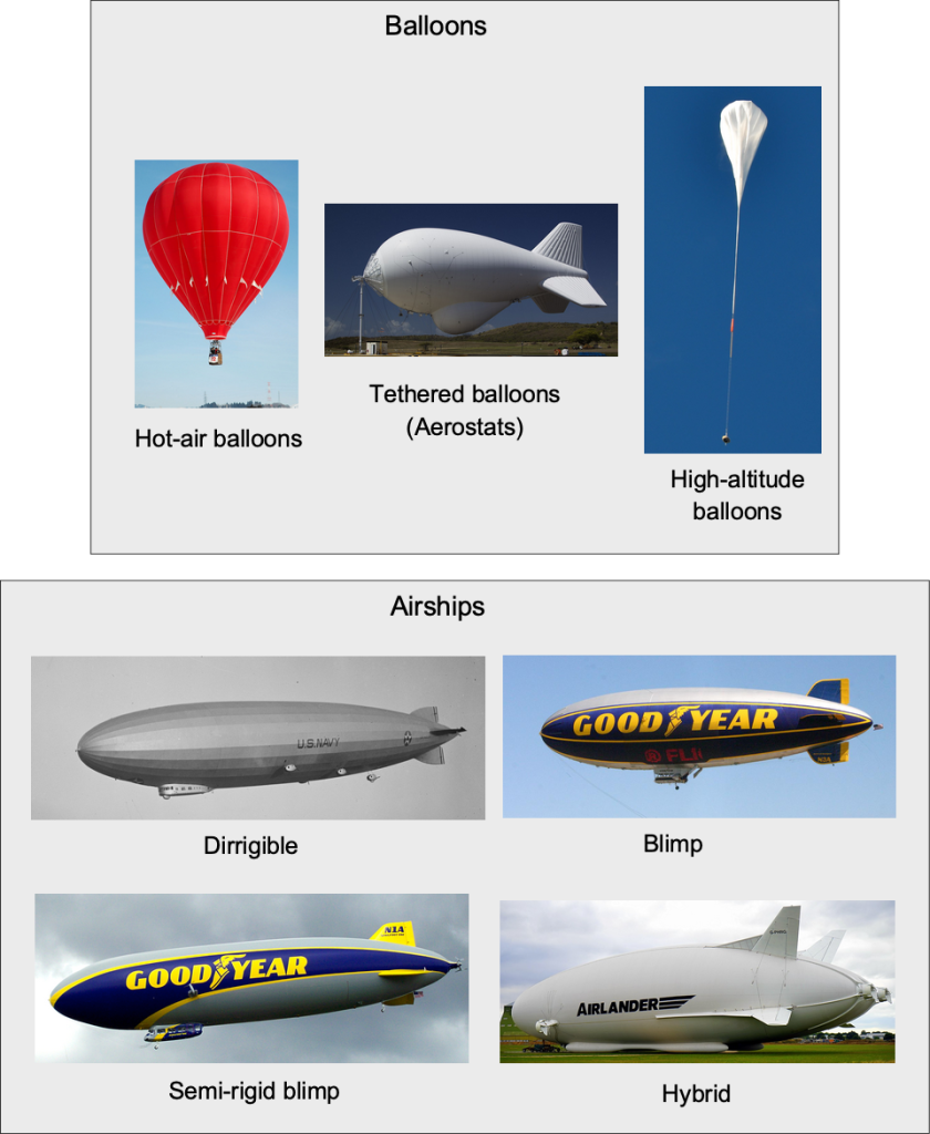
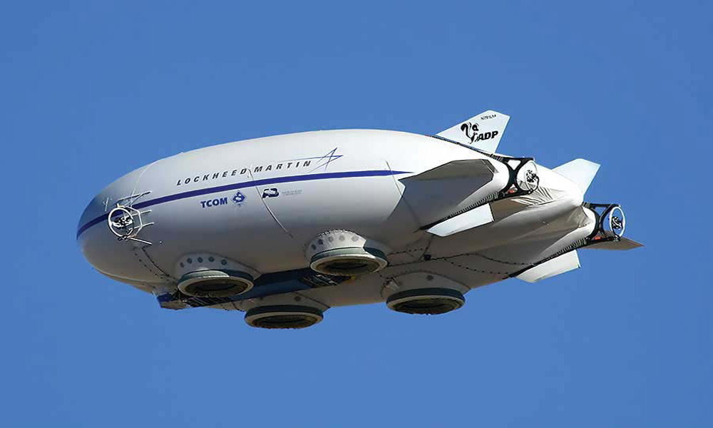
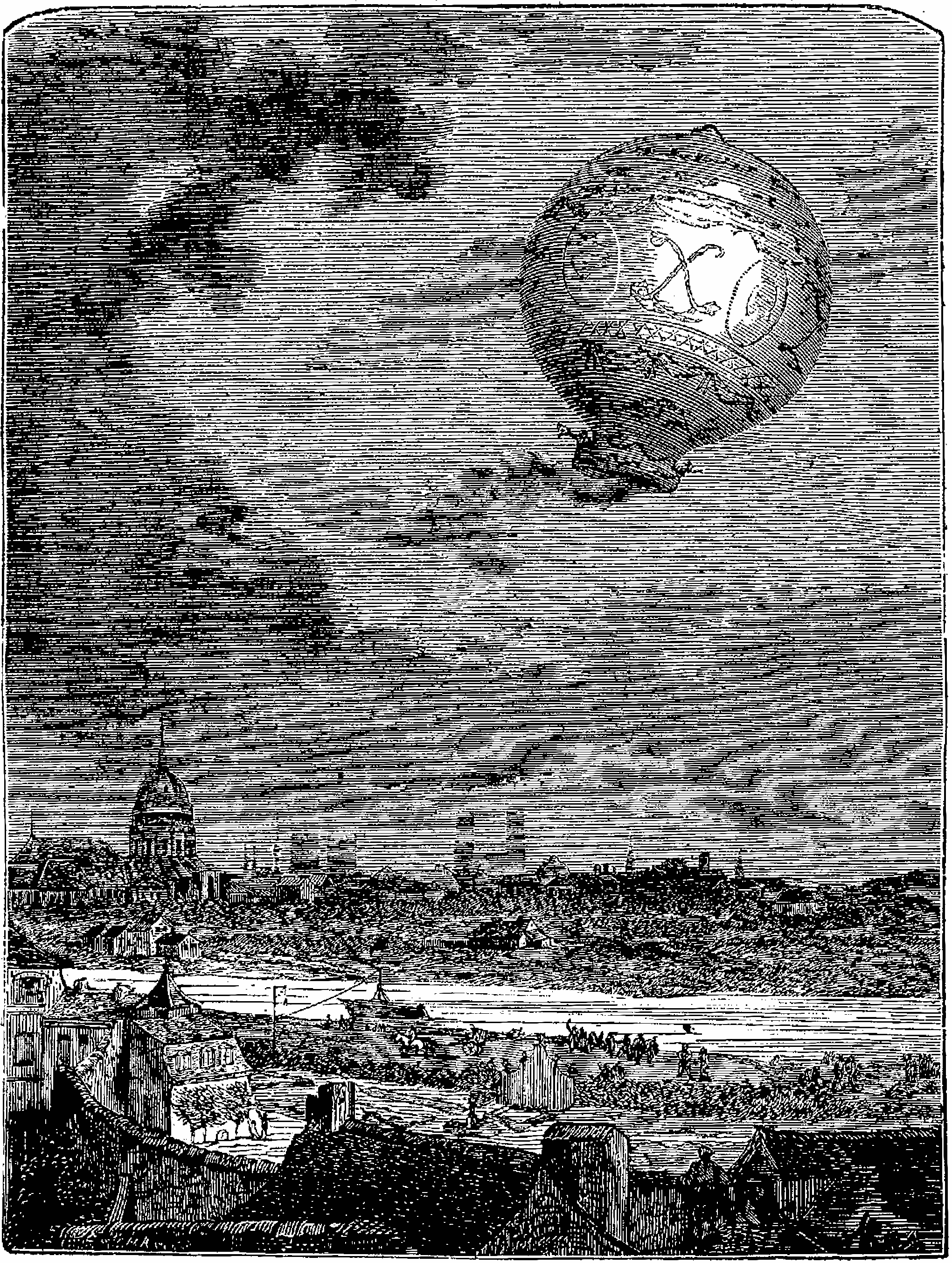
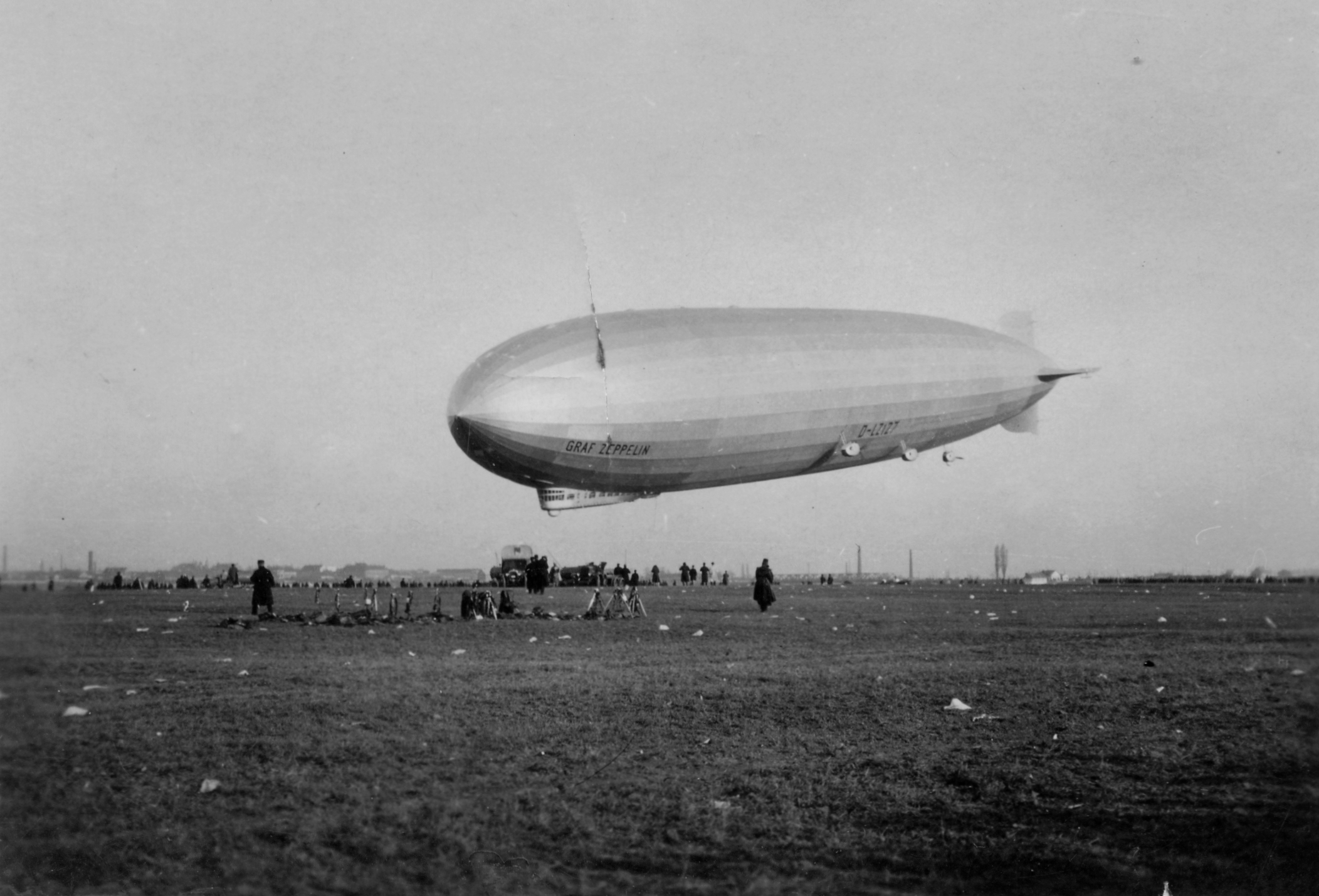
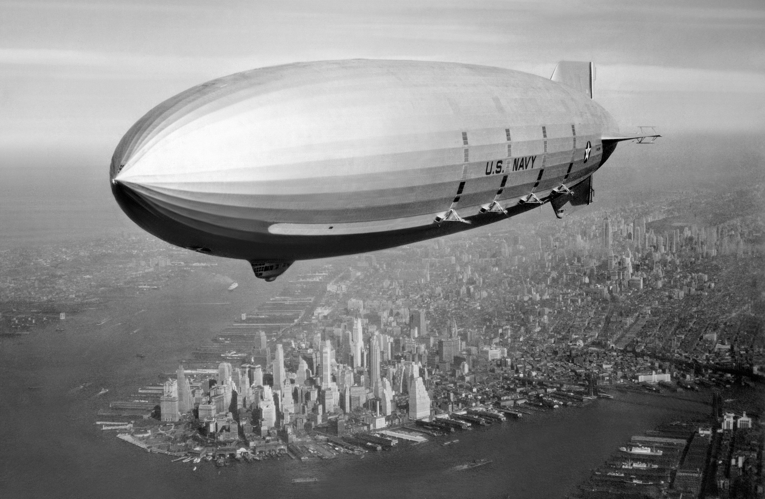
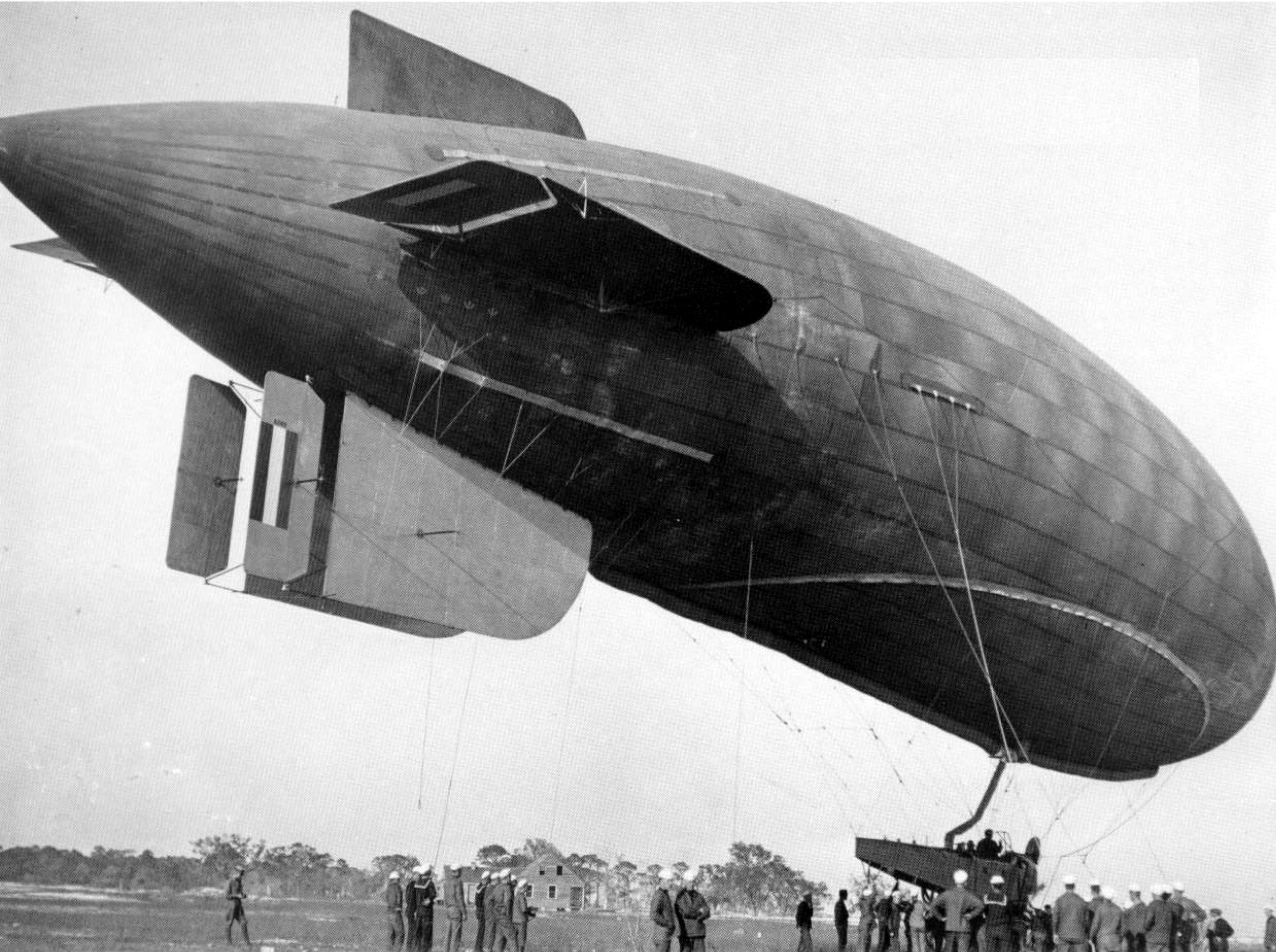
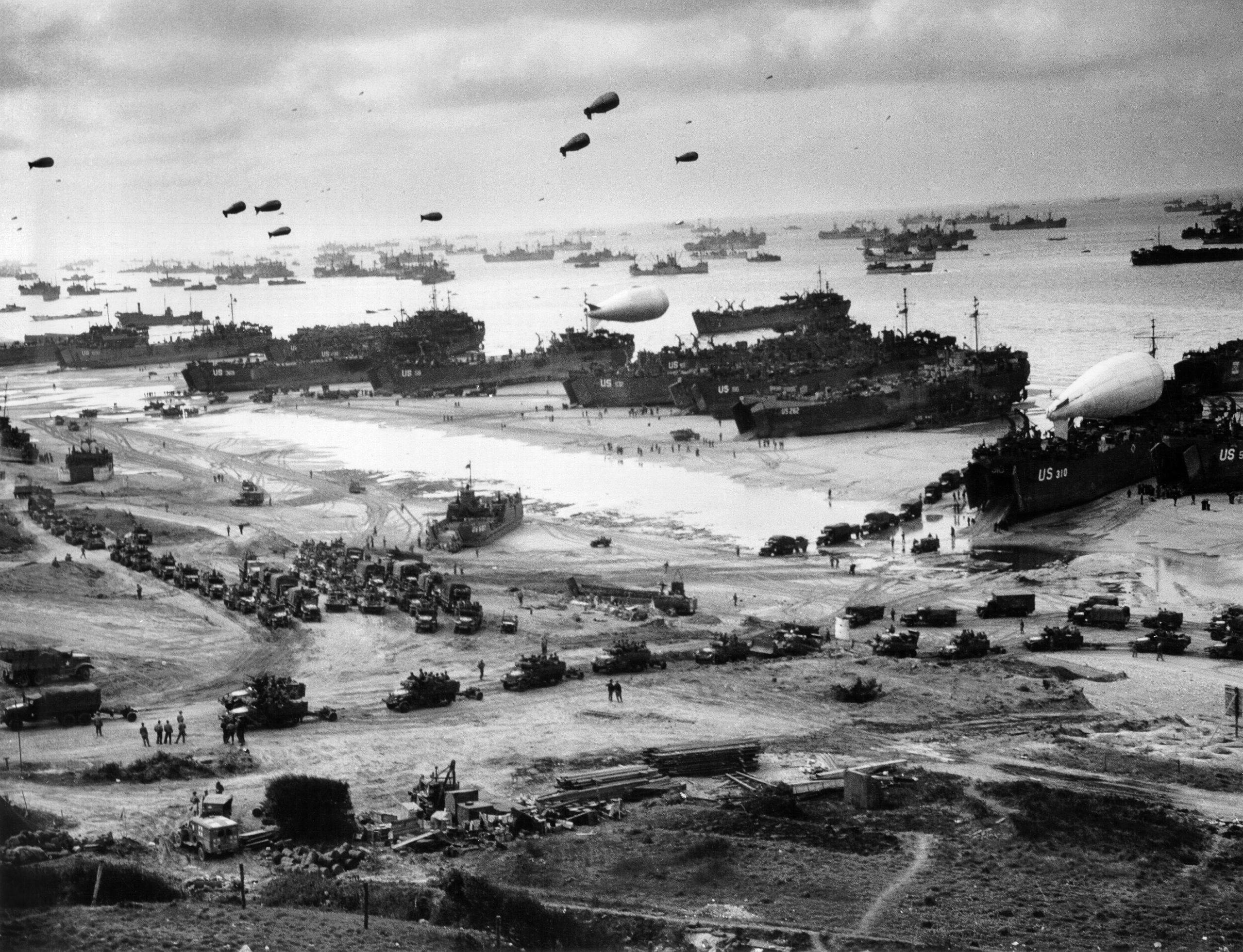
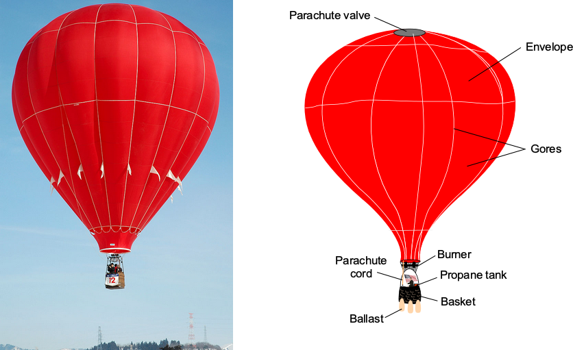
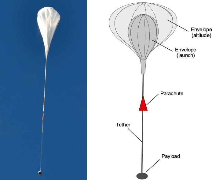
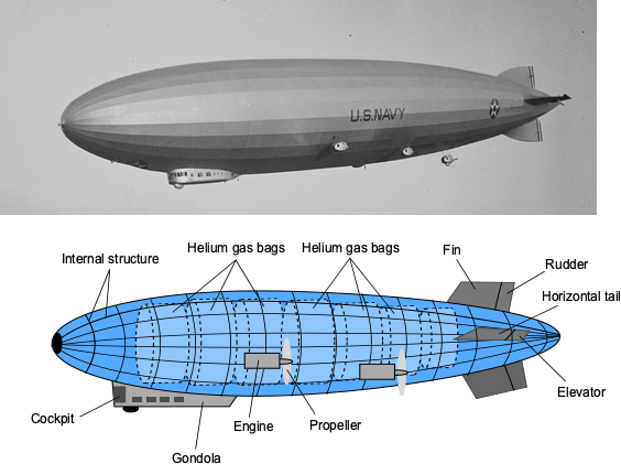
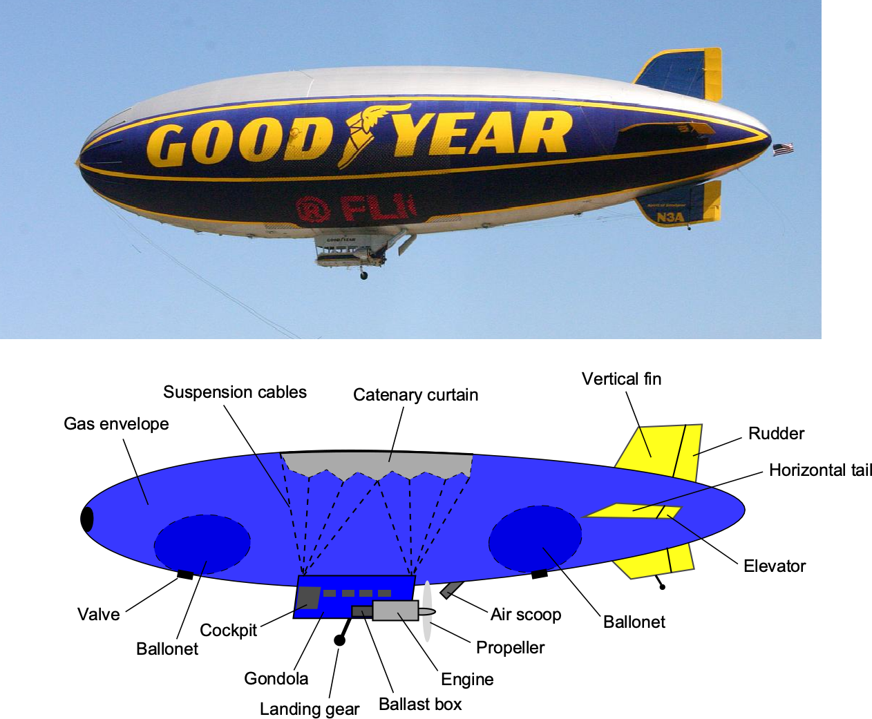
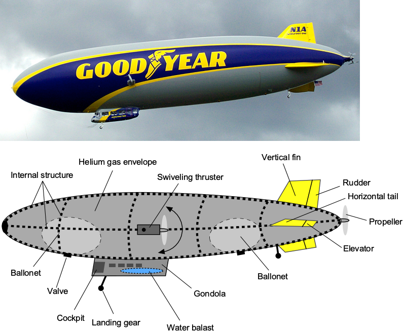
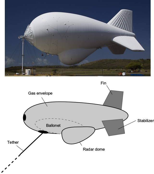
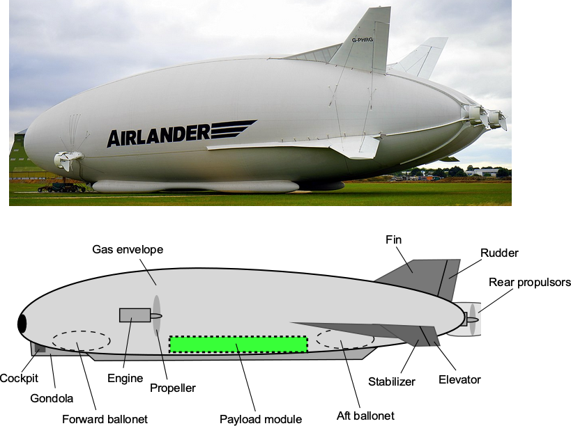
 , giving only about 16% less buoyancy. This marginal gain does not justify the engineering difficulties involved in constructing a vacuum airship. Helium and hydrogen-filled airships, which are far easier to build and maintain, already achieve near-optimal buoyancy without the structural challenges posed by vacuum containment.
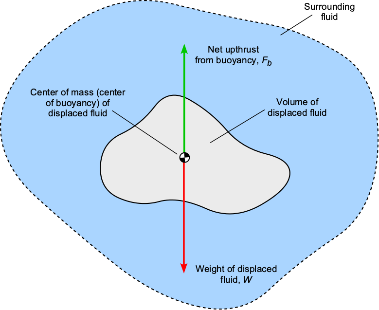
 (the heaviest) to
  (the lightest). If the object is entirely immersed in the fluid, then the buoyancy force,
  , will be
 is the volume of the object and hence the volume of the displaced fluid, and
  is the density of the displaced fluid. The buoyancy force only depends on the weight of the fluid displaced by the object, not the weight of the object. However, the net force on the object is a balance between the buoyancy and the weight, i.e.,
 is the density of the object.
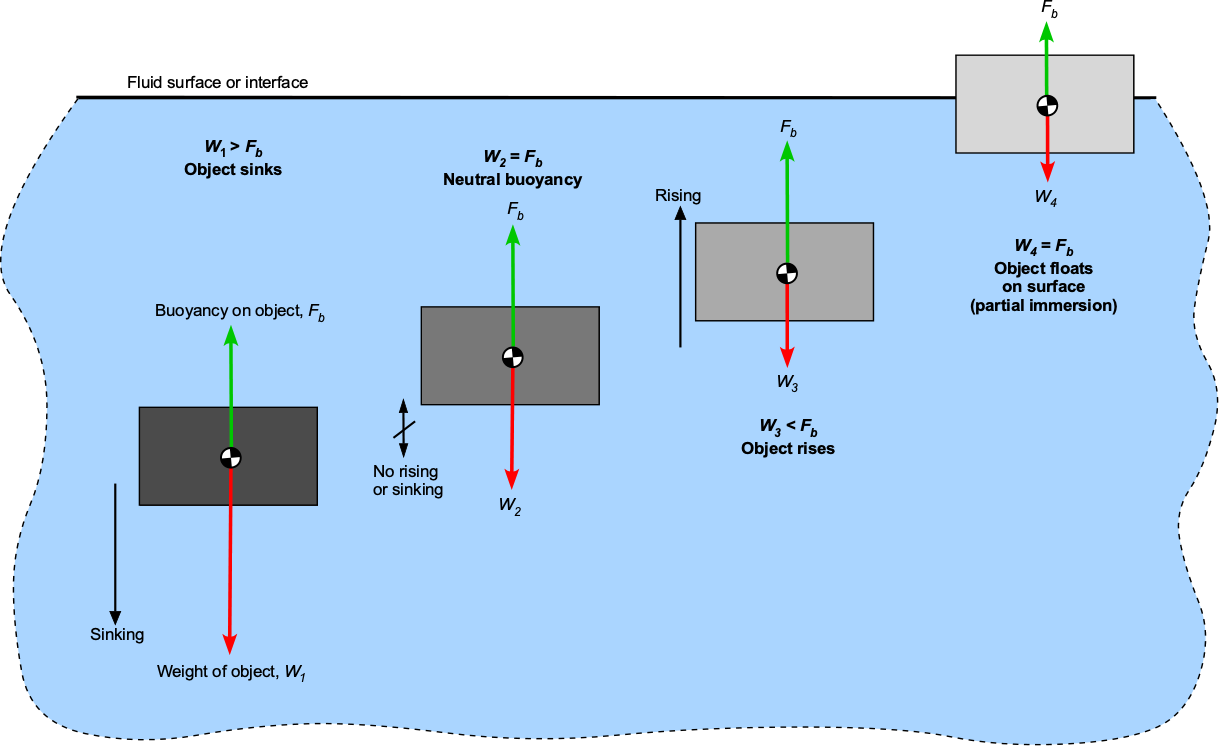
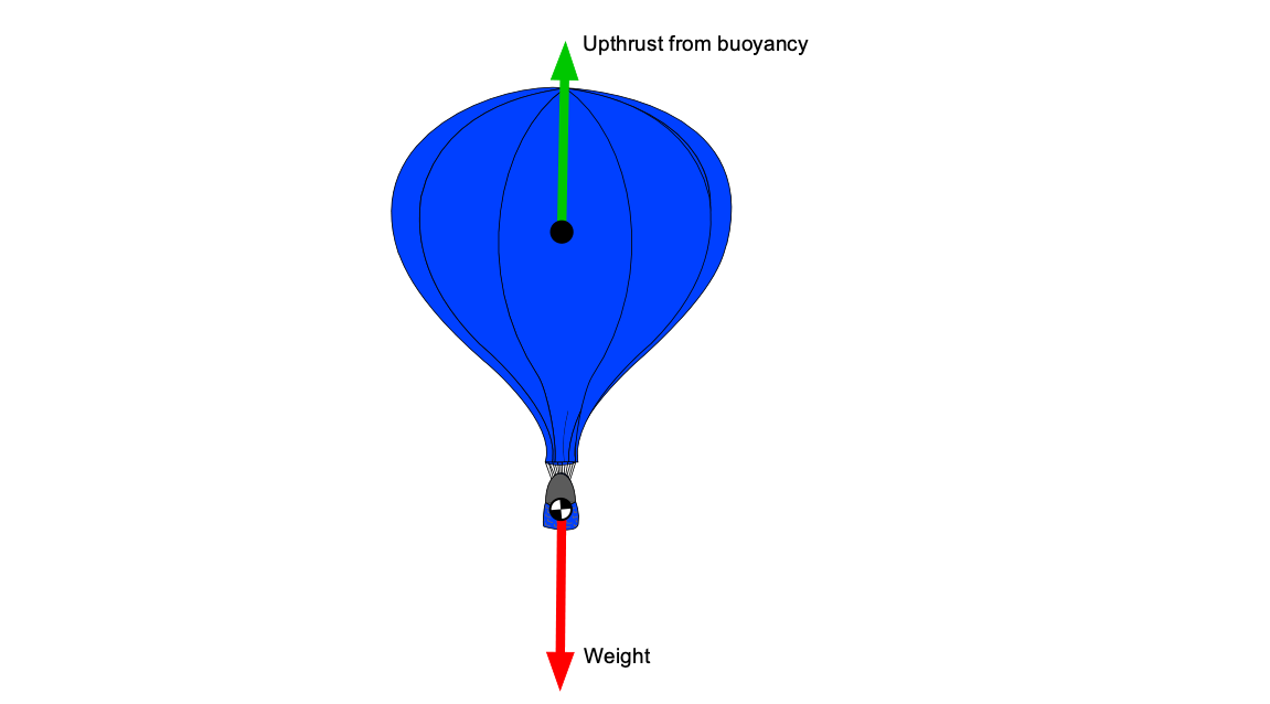
 , plus the weight of the balloon itself,
  , equals the buoyancy lift,
  , or upthrust


 C. With all its cargo, the balloon has a mass of 500 kg (excluding the air in the balloon), displacing a volume of 7,000 m3. Assume that the pressure inside the balloon is equal to the pressure outside. Determine the air temperature inside the balloon to give it neutral buoyancy. At 1,100 m, the air density can be considered 1.102 kg/m3.
 + the weight of the balloon itself
 ![\[ F_b - \left( W_b + W_{\rm hot} \right) = 0 \]](https://eaglepubs.erau.edu/app/uploads/quicklatex/quicklatex.com-978f8c1bf552c54f1638fdda7302478a_l3.svg "Rendered by QuickLaTeX.com")
 = 7,000 m
 . Therefore, the weight of cool air displaced by the balloon is then.
![\[ W_{\rm cool} = {\cal{V}} \, \varrho_{1100} \, g = 7,000 \times 1.102 \times 9.81 = 75,674.3~\mbox{N} \]](https://eaglepubs.erau.edu/app/uploads/quicklatex/quicklatex.com-e5e9d1f0fe47b7aa87c81236f499e6d1_l3.svg "Rendered by QuickLaTeX.com")
 = 500
= 500 9.81 = 4905.0 N. Notice that
  is the density of the displaced air at a height of 1,100 m, which is given as 1.102 kg m
 .
. if the net vertical force is zero), the weight of the hot air in the balloon must be
![\[ W_{\rm hot} = F_b - W_b = 75,674.3 - 4905.0 = 70,769.3~\mbox{N} \]](https://eaglepubs.erau.edu/app/uploads/quicklatex/quicklatex.com-9758e71067e6c4a83d866c128a5cef03_l3.svg "Rendered by QuickLaTeX.com")
![\[ \varrho_{\rm hot} = \frac{W_{\rm hot} }{g \cal{V}} = \frac{70,769.3}{9.81 \times 7,000} = 1.031~\mbox{kg m}^{-3} \]](https://eaglepubs.erau.edu/app/uploads/quicklatex/quicklatex.com-d87a8878d087caa41dcd164bdcabf6e6_l3.svg "Rendered by QuickLaTeX.com")
![\[ p = \varrho \, R \, T \]](https://eaglepubs.erau.edu/app/uploads/quicklatex/quicklatex.com-cff84f3130a2abf8502dc6b70639140e_l3.svg "Rendered by QuickLaTeX.com")
![\[ p = \varrho_{\rm cool} \, R \, T_{\rm cool} = \varrho_{\rm hot} \, R \, T_{\rm hot} \]](https://eaglepubs.erau.edu/app/uploads/quicklatex/quicklatex.com-ff6be85e3f02f8b8b274d443ef667cb2_l3.svg "Rendered by QuickLaTeX.com")
![\[ \frac{T_{\rm hot}}{T_{\rm cool}} = \frac{\varrho_{\rm cool}}{\varrho_{\rm hot}} = \frac{1.102}{1.1031} = 1.069 \]](https://eaglepubs.erau.edu/app/uploads/quicklatex/quicklatex.com-9933b62e92755f136c64486b539842f5_l3.svg "Rendered by QuickLaTeX.com")
![\[ T_{\rm hot} = 1.069 \, T_{\rm cool} = 1.069 \times 283.65 = 303.22~\mbox{$^{\circ}$K} \approx 30.1~\mbox{$^{\circ}$C} \]](https://eaglepubs.erau.edu/app/uploads/quicklatex/quicklatex.com-b80a051305d50bcde5200df64fccaa1f_l3.svg "Rendered by QuickLaTeX.com")
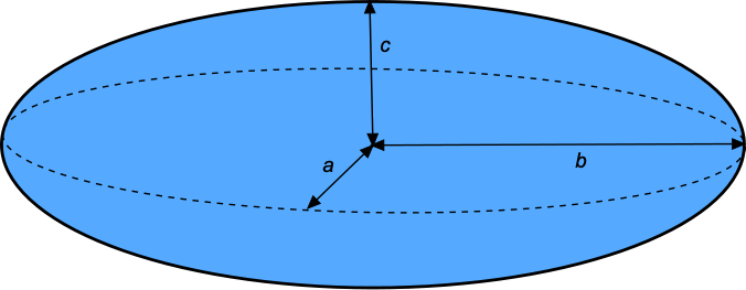
 , of a general ellipsoid is
 , or a sphere where
  then
then

 , then this formula is the volume of a sphere, i.e.,
 and
and  is
is

 of an prolate spheroid is
 is called the “wetted area.
 , Eq.
, Eq. 

 and
and  , then

 = 8/5.
 , for an prolate spheroid is defined as
 is the maximum diameter.
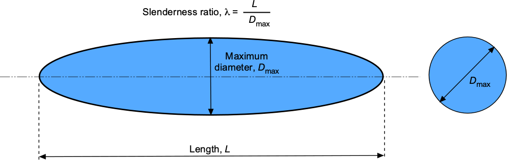
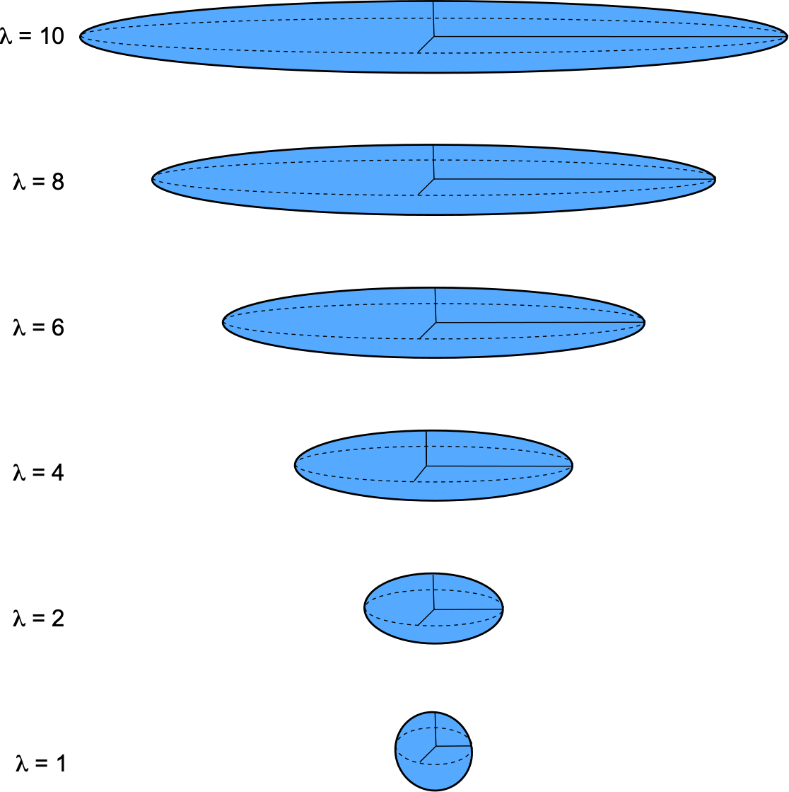

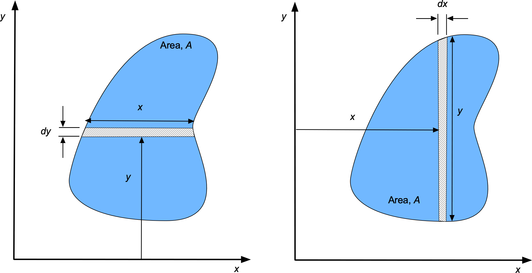


 , is then determined using

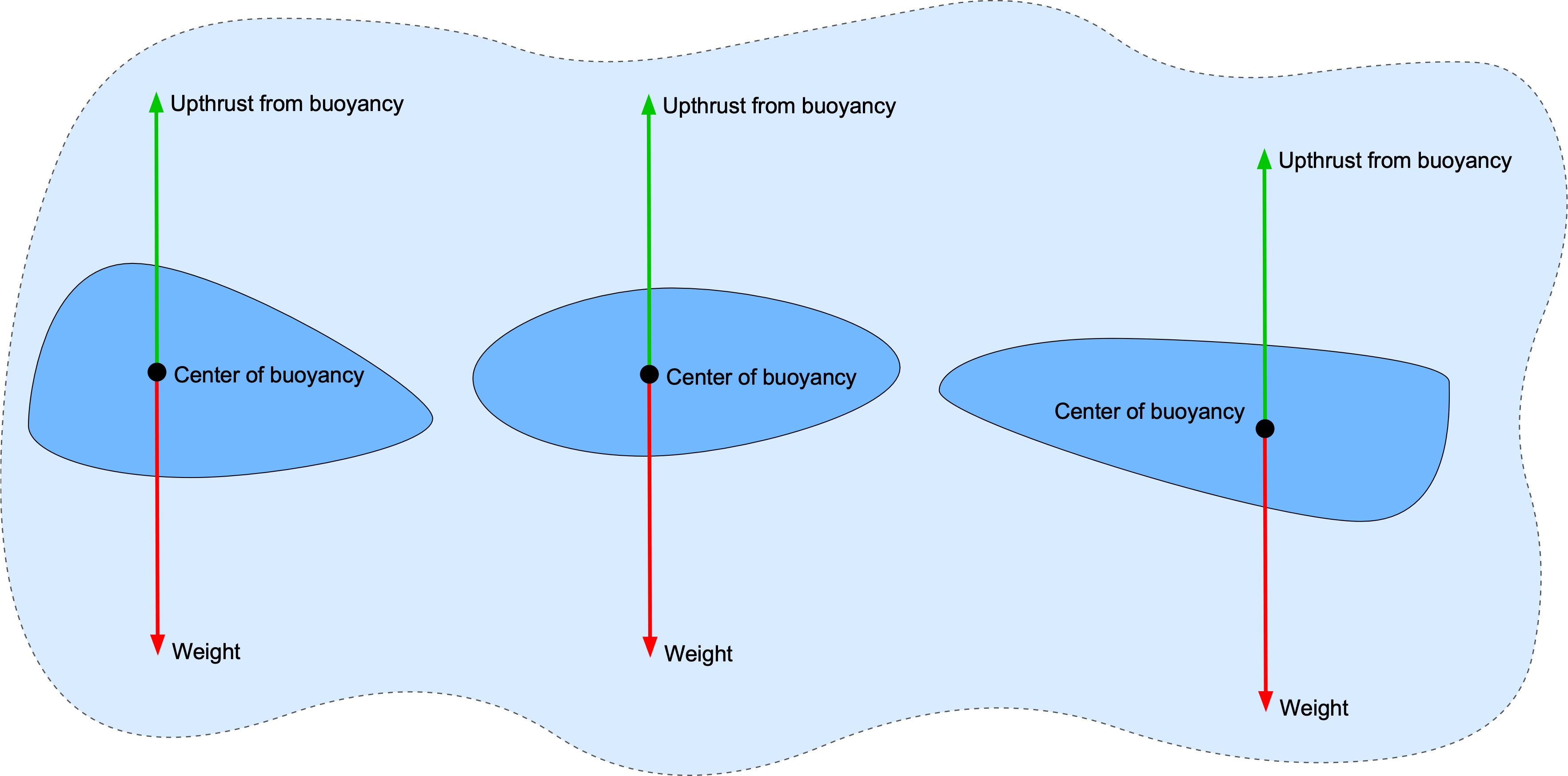

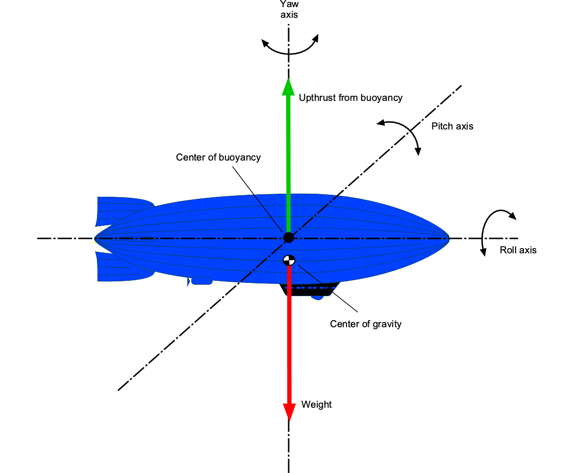

 is the density of air, and
  is the density of helium gas. If the net sum of the structural, fuel, and payload weight of the airship is
  , then for vertical force equilibrium and neutral buoyancy, then
![\[ L = \left( \varrho_{\rm air} - \varrho_{\rm He} \right) g {\cal{V}} \]](https://eaglepubs.erau.edu/app/uploads/quicklatex/quicklatex.com-e863cc53b46ab1de9689e31bca3b2ba6_l3.svg "Rendered by QuickLaTeX.com")
 , plus the fuel weight,
  , plus the payload,
  , i.e.,
![\[ W = W_E+ W_F + W_P \]](https://eaglepubs.erau.edu/app/uploads/quicklatex/quicklatex.com-01f9247b232214bd624e7177f6b9eee0_l3.svg "Rendered by QuickLaTeX.com")
 , so
, so![\[ W_E + W_F + W_P = \left( \varrho_{\rm air} - \varrho_{\rm He} \right) g {\cal{V}} \]](https://eaglepubs.erau.edu/app/uploads/quicklatex/quicklatex.com-e65ccdaac861ae11e06799966dc31ab9_l3.svg "Rendered by QuickLaTeX.com")
![\[ W_P = \left( \varrho_{\rm air} - \varrho_{\rm He} \right) g {\cal{V}} - W_E - W_F \]](https://eaglepubs.erau.edu/app/uploads/quicklatex/quicklatex.com-535b9be9cb981c5745a51fc089dd5984_l3.svg "Rendered by QuickLaTeX.com")
![\[ W_P = \left( 0.002378 - 0.0003192 \right) \times 32.17 \times 296,520 - 14,188.0 - 960.0 = 4,429.2~\mbox{lb} \]](https://eaglepubs.erau.edu/app/uploads/quicklatex/quicklatex.com-38a821347fa263321ada2810f7f5ac6f_l3.svg "Rendered by QuickLaTeX.com")
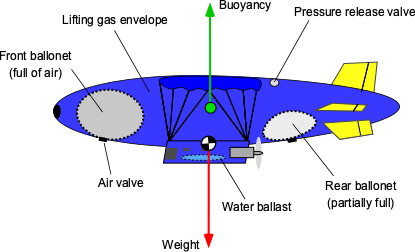

 is the volume of the buoyant gas contained in the envelope,
  is the density of the buoyant gas, e.g., helium.
 , is defined as the volume fraction of the total volume of the envelope occupied by the buoyant gas, i.e., the fraction not occupied by the ballonets. If the total volume of the envelope is

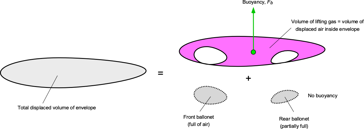
 , with
  cells has an inflation fraction,
  , then the volume of buoyant gas will be
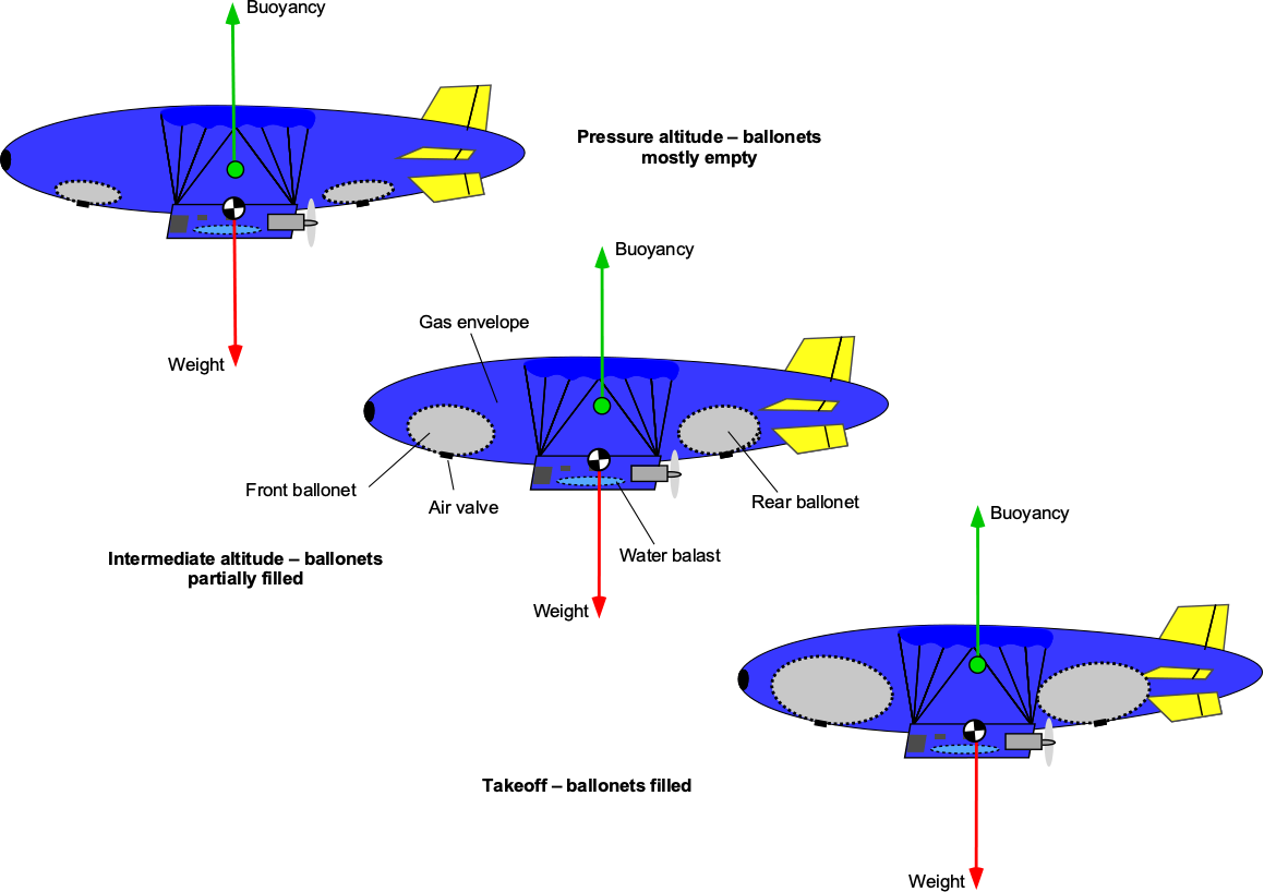
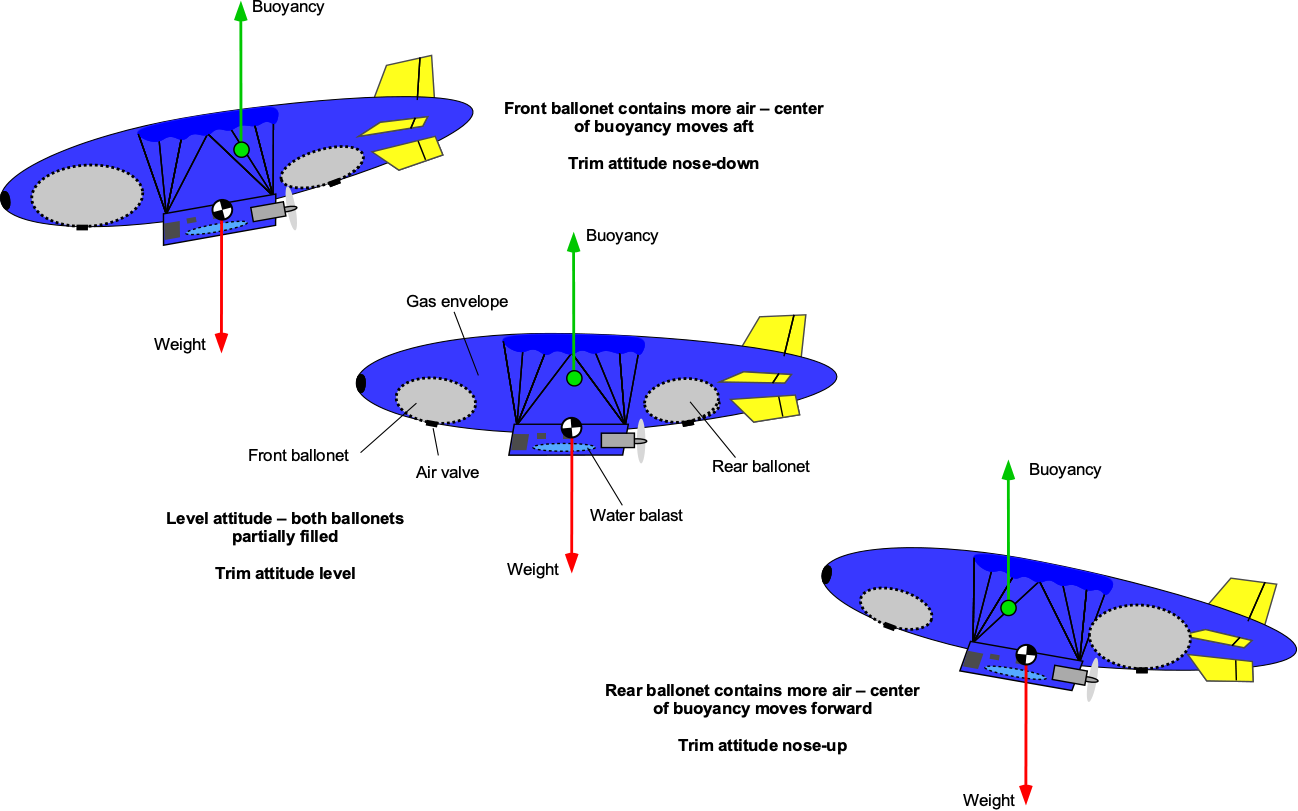
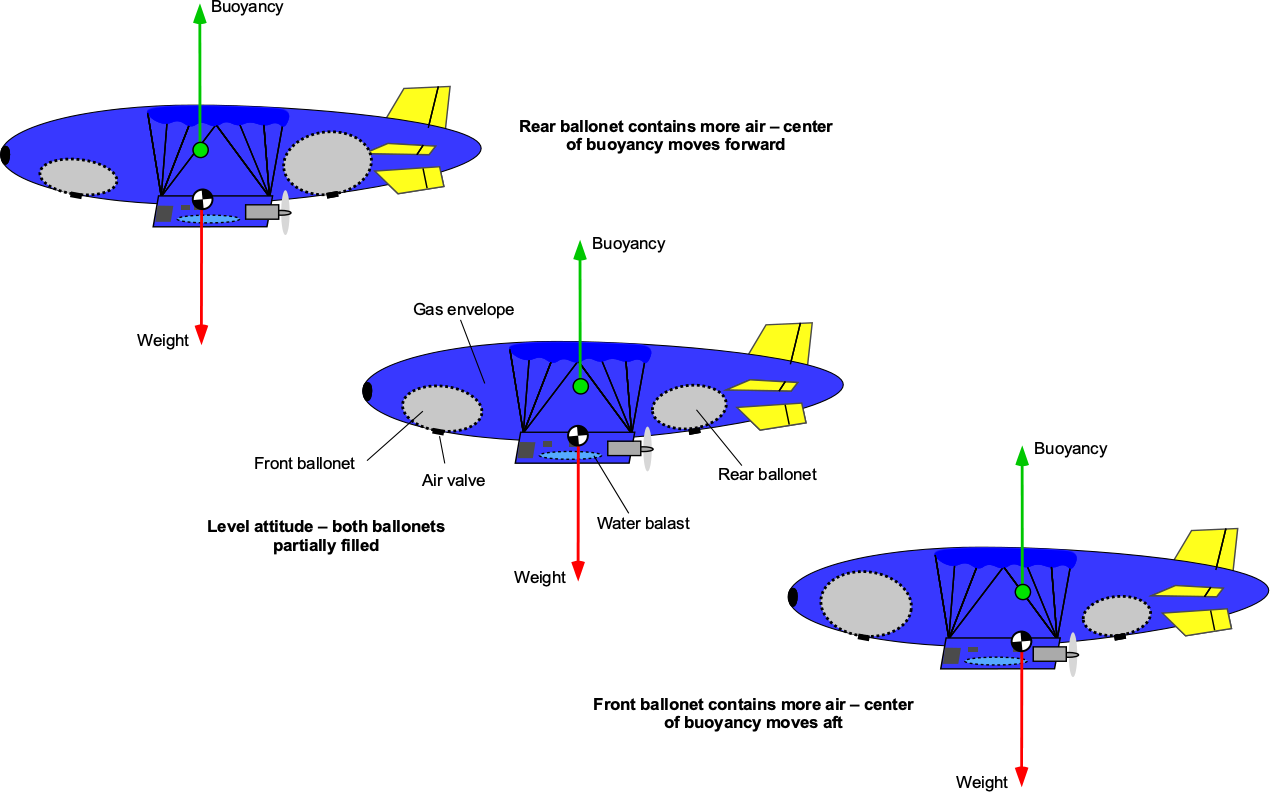
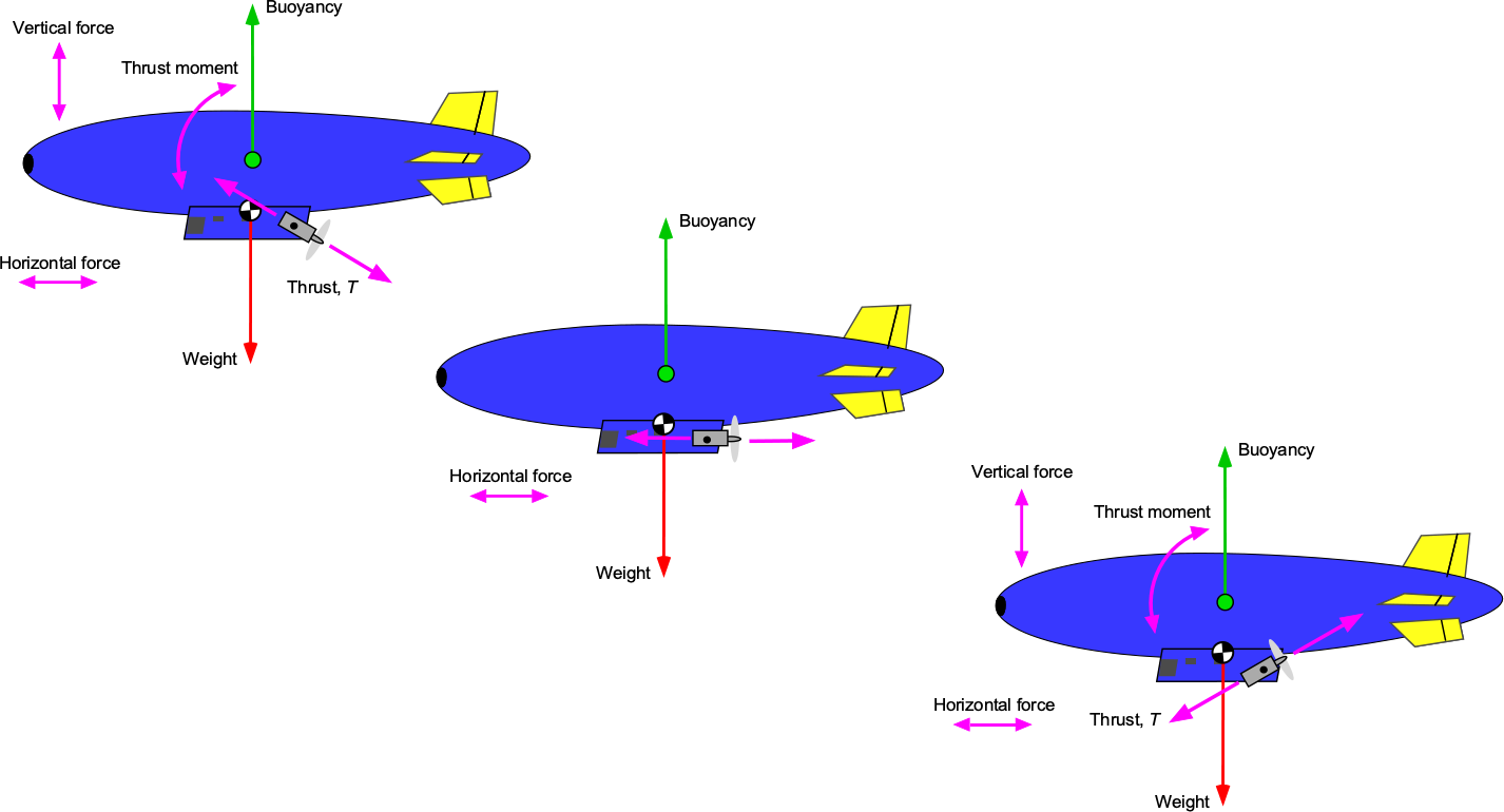
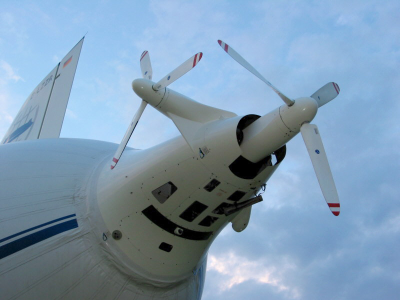
 = 10 m. Two ballonets containing air can expand into the helium gas bag to reduce its volume and affect the airship’s overall buoyancy. The airship’s total mass, including the full load of helium, is 11,500 kg. The density of air is
  , and the density of helium is
  . Determine the air volume that must be pumped into the ballonets for the airship to achieve neutral buoyancy.
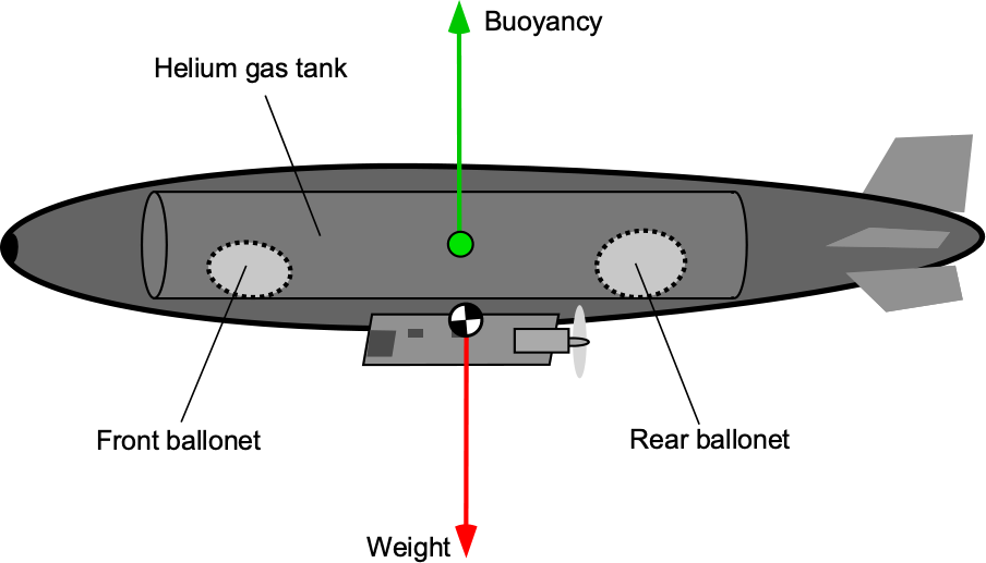
![\[ {\cal{V}}_{\text{gas\_bag}} = \pi R^2 L = \pi (10.0)^2 \times 40 = 4,000 \pi \, \text{m}^3 \approx 12{,}566.37 \, \text{m}^3 \]](https://eaglepubs.erau.edu/app/uploads/quicklatex/quicklatex.com-5f1515c08e4db1600a2a0037eb4a2ea3_l3.svg "Rendered by QuickLaTeX.com")
![\[ W = M g = 11{,}500 \times 9.81 = 112{,}215.0 \, \text{N} \]](https://eaglepubs.erau.edu/app/uploads/quicklatex/quicklatex.com-9641361bf7ede3745dc221de02612026_l3.svg "Rendered by QuickLaTeX.com")
![\[ F_b = {\cal{V}}_{\text{gas\_bag}} \, \varrho_{\text{air}} \, g \]](https://eaglepubs.erau.edu/app/uploads/quicklatex/quicklatex.com-de8fa010216631a19a2791eb60c94261_l3.svg "Rendered by QuickLaTeX.com")
 is the full expanded volume of the helium gas bag (calculated above). Therefore,
![\[ F_b = 4{,}000 \pi \times 1.225 \times 9.81 = 4{,}000 \times 3.14159 \times 1.225 \times 9.81 = 151{,}778.4 \, \text{N} \]](https://eaglepubs.erau.edu/app/uploads/quicklatex/quicklatex.com-7559c2a6676c6f025eebc75dcbfaed77_l3.svg "Rendered by QuickLaTeX.com")
 . The volume of air
  needed to displace the initial value of helium when air is pumped into the ballonets can be expressed in terms of
![\[ F_b = ( {\cal{V}}_{\text{gas\_bag}} - {\cal{V}}_{\text{air}}) \, \varrho_{\text{air}} \, g = W \]](https://eaglepubs.erau.edu/app/uploads/quicklatex/quicklatex.com-0a0c8ff876dcfe74e7f28d63a4c42e84_l3.svg "Rendered by QuickLaTeX.com")
![\[ {\cal{V}}_{\text{air}} = {\cal{V}}_{\text{gas\_bag}} - \frac{W}{\varrho_{\text{air}} \ g} = 12{,}566.37 - \frac{112{,}215}{1.225 \times 9.81} \approx 3{,}2212 \, \text{m}^3 \]](https://eaglepubs.erau.edu/app/uploads/quicklatex/quicklatex.com-9e39a562a58342da5c356e3545de5d66_l3.svg "Rendered by QuickLaTeX.com")
 .
.![\[ F_b = (\varrho_{\rm air} - \varrho_{\rm gas}) \, {\cal{V}} \, g, \]](https://eaglepubs.erau.edu/app/uploads/quicklatex/quicklatex.com-49966f1e648d282679b671b6c486495b_l3.svg "Rendered by QuickLaTeX.com")
 is the gas density (hydrogen or helium), and
 ![\[ W_P = F_b - W_E - W_F \]](https://eaglepubs.erau.edu/app/uploads/quicklatex/quicklatex.com-2951e009c7513321bc5a56db8e330759_l3.svg "Rendered by QuickLaTeX.com")
![\[ W_P^{\rm H_2} = (\varrho_{\rm air} - \varrho_{\rm H_2}) {\cal{V}} g - W_E - W_F, \qquad W_P^{\rm He} = (\varrho_{\rm air} - \varrho_{\rm He}) {\cal{V}} g - W_E - W_F, \]](https://eaglepubs.erau.edu/app/uploads/quicklatex/quicklatex.com-4098ed16eb5f25c7a64e4ce2f372bcff_l3.svg "Rendered by QuickLaTeX.com")
![\[ W_P^{\rm H_2} - W_P^{\rm He} = (\varrho_{\rm He} - \varrho_{\rm H_2}) {\cal{V}} g. \]](https://eaglepubs.erau.edu/app/uploads/quicklatex/quicklatex.com-89f2f32c4cd24e9862c4a24c7bfed6cf_l3.svg "Rendered by QuickLaTeX.com")
![\[ \frac{W_P^{\rm H_2} - W_P^{\rm He}}{W_P^{\rm He}}= \frac{\varrho_{\rm He} - \varrho_{\rm H_2}}{(\varrho_{\rm air} - \varrho_{\rm He}) - \dfrac{W_E + W_F}{{\cal{V}} g}} \]](https://eaglepubs.erau.edu/app/uploads/quicklatex/quicklatex.com-dd3e76ab0e5aabe276395def85dbb0f8_l3.svg "Rendered by QuickLaTeX.com")
![\[ \mbox{Dynamic lift = Aerodynamic lift + Tail lift + Propulsive lift} \]](https://eaglepubs.erau.edu/app/uploads/quicklatex/quicklatex.com-b0b7642f547f6e4f77a2d4c1ead09aa8_l3.svg "Rendered by QuickLaTeX.com")
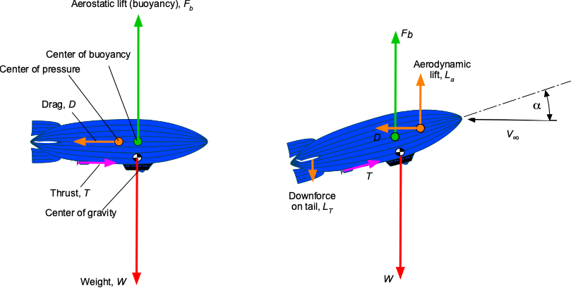


 , is defined by
 , i.e.,
  , is defined by

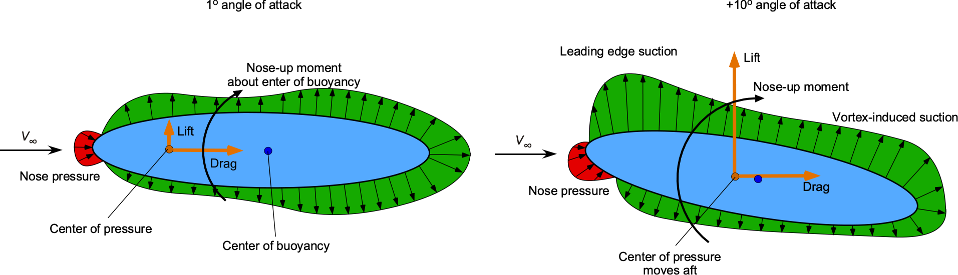
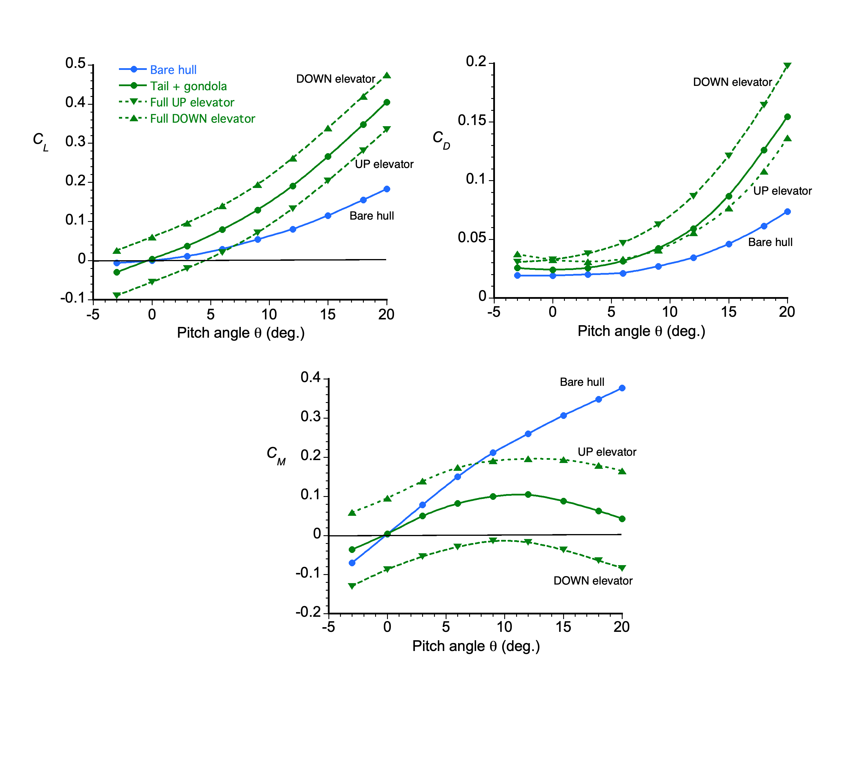
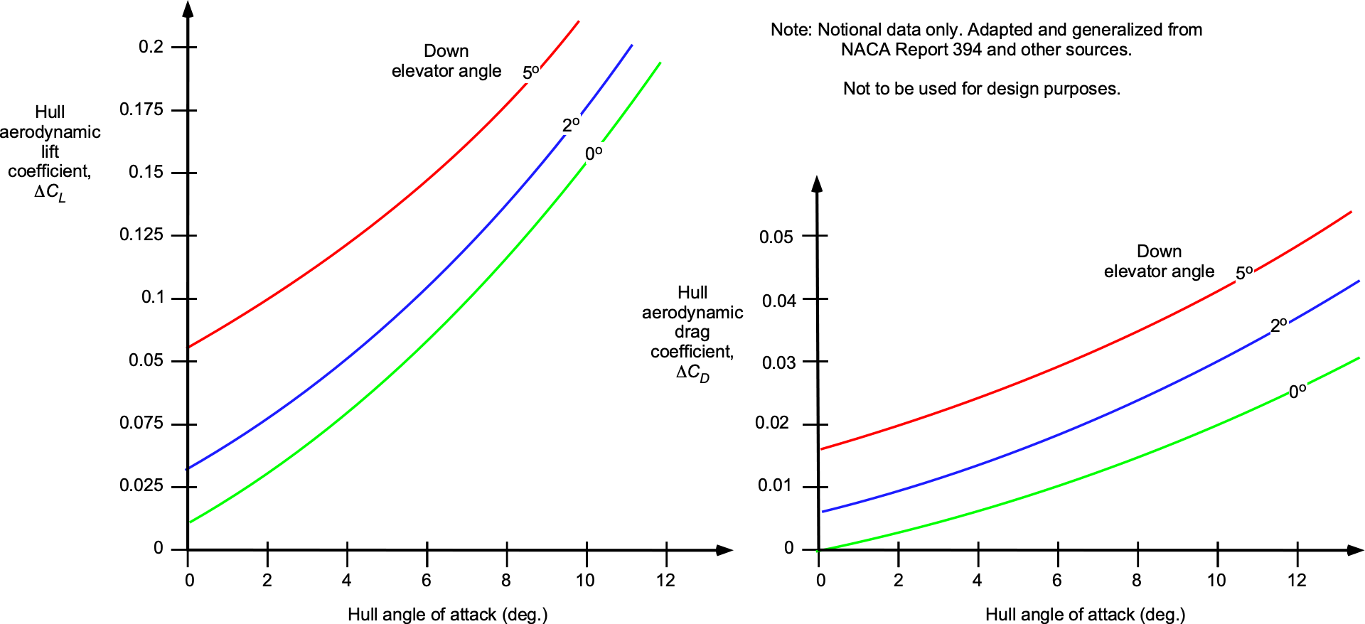

 0.000146 per degree angle of attack. With elevator deflection,
  , this latter equation can be modified to
 0.01 per degree angle of elevator deflection.
 will vary depending on the slenderness of the airship and other shape factors, including the effects of tail surfaces, gondola, etc., a value of
  0.01 seems reasonable for preliminary design based on the results shown in the previous plot. Furthermore, a value of
  of about 0.02 per degree is a reasonable approximation for the effects of elevator deflection.
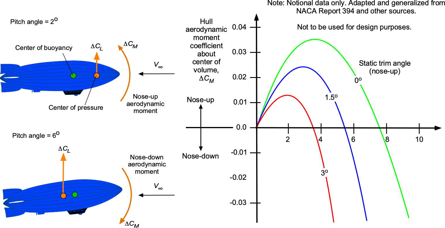

 . The equivalent “flat plate” skin friction drag coefficient,
  , is a function of Reynolds number as given by
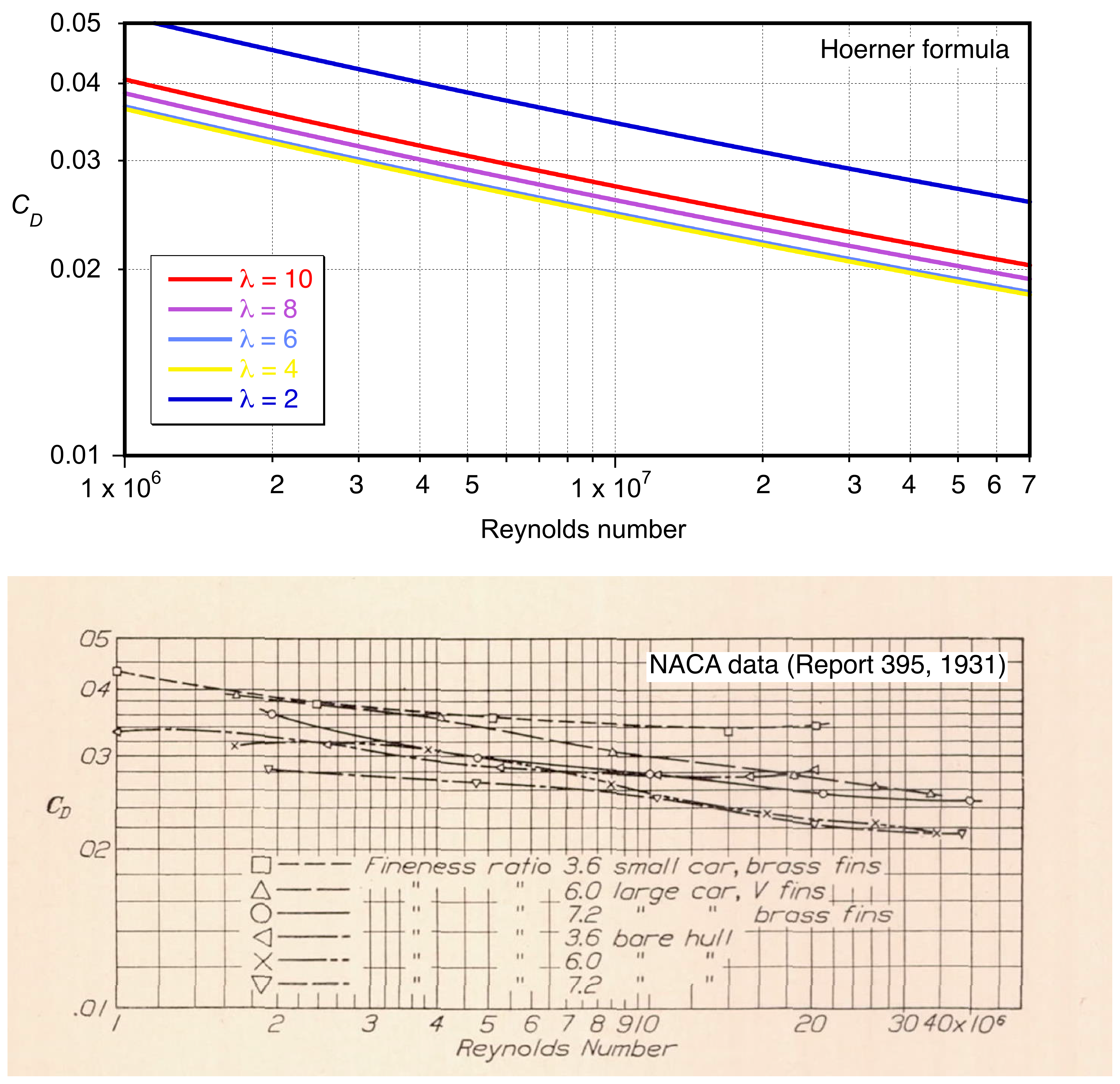
 = 0.023 for the hull alone and
  for the complete airship, including nacelles, fins, etc. Recall that the drag on an airship is mostly from boundary layer shear stress or skin friction over the large surface area of the gas envelope. A larger airship with a higher Reynolds number at the same airspeed will have a lower drag coefficient. Therefore, its drag, being proportional to the wetted surface, grows with less than the square of the increase in the length scale, while the aerostatic lift is proportional to the cube of the length scale.
 , so
, so


 can be considered as the net efficiency of the propulsive system (engine and propeller combined); notice that this value may vary with airspeed.

 , as shown in the figure below. In this case, power will increase proportionally with the cube of the airspeed according to

 is the buoyant lift, and
  is the aerodynamic lift. The parameter
  is the lift sharing fraction, so
  0.9 when 90% of the lift comes from buoyancy. The aerodynamic lift is given by

 . The drag coefficient (assuming no elevator deflection) is then


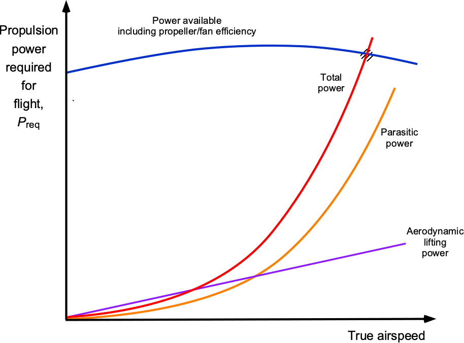
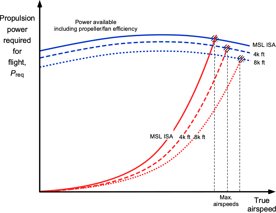
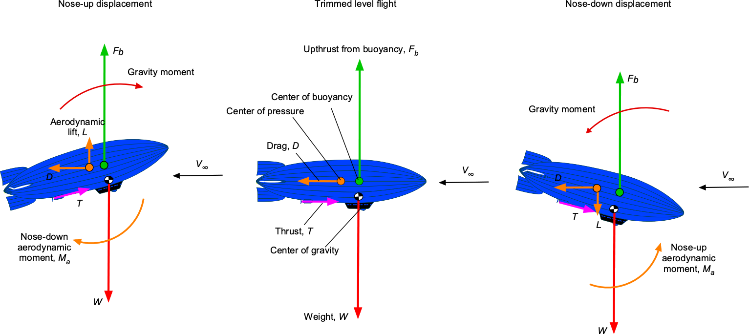
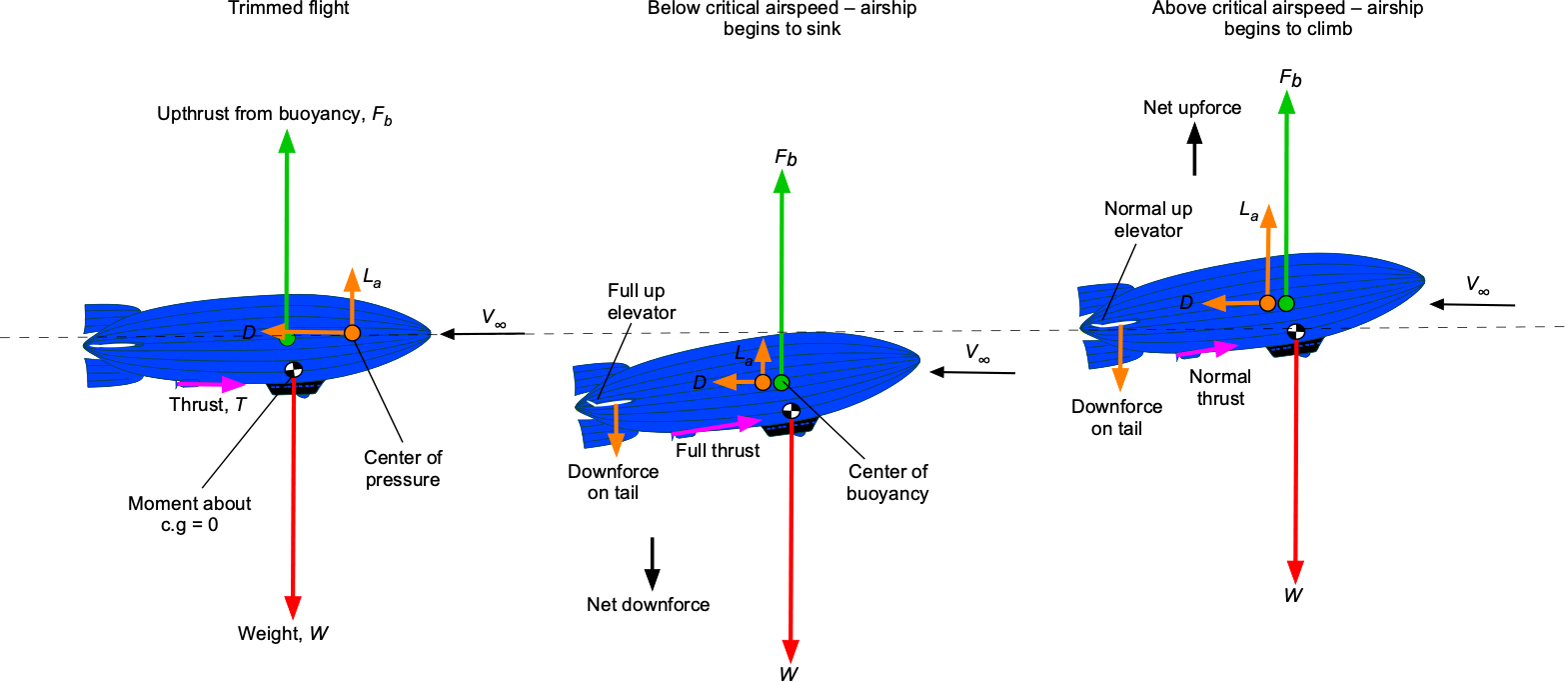
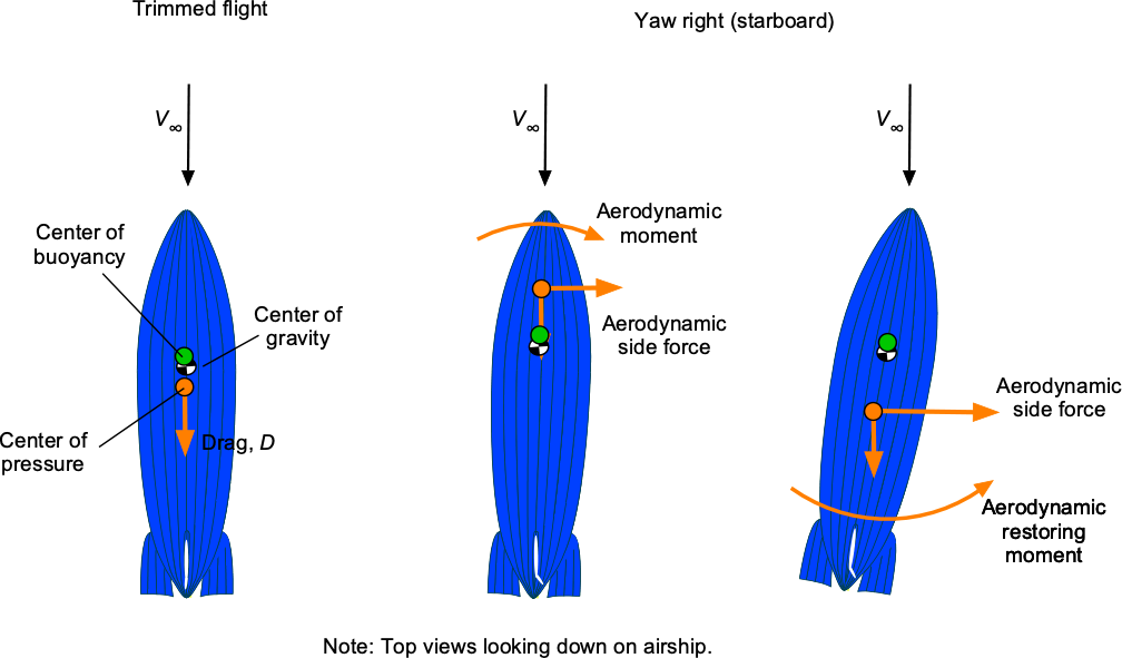
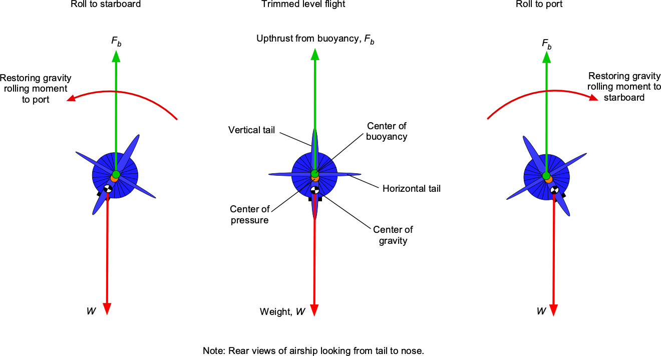
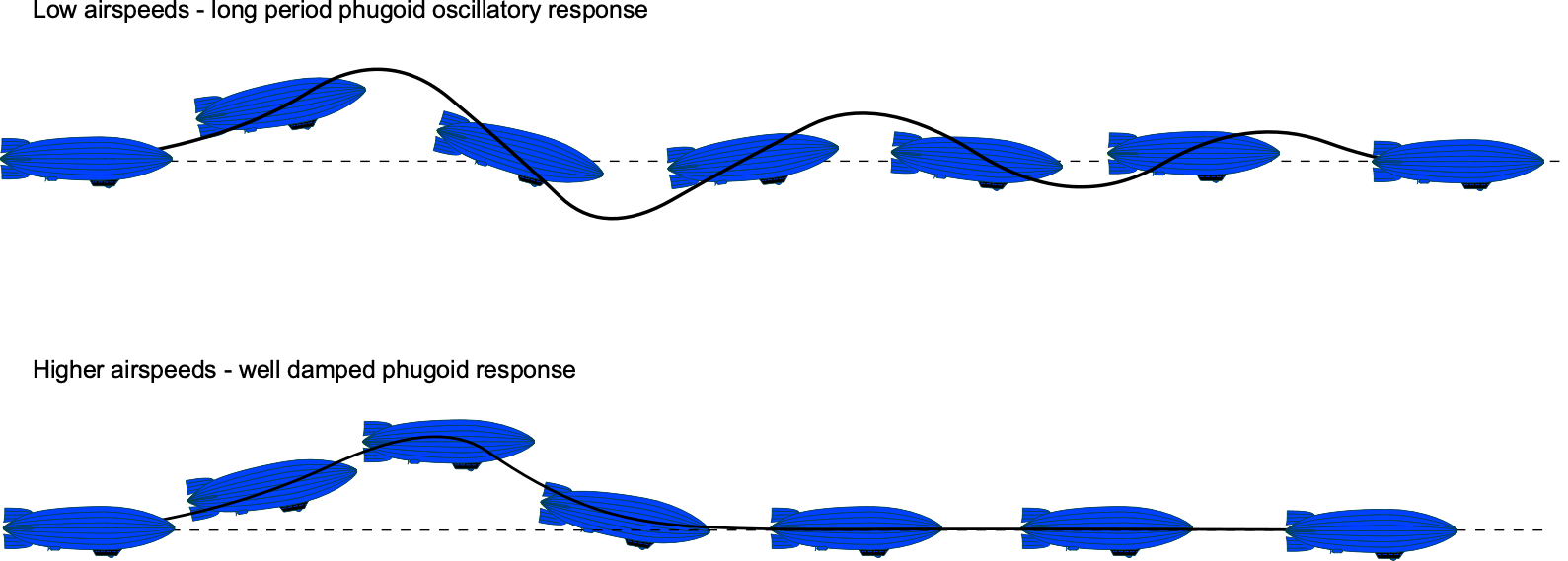
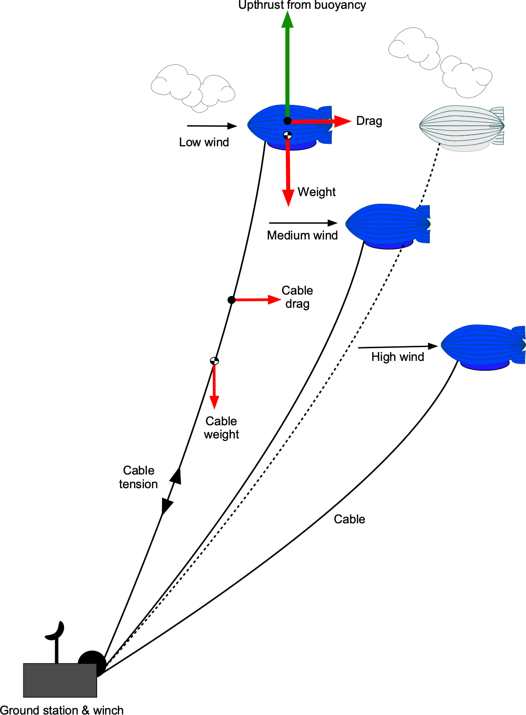
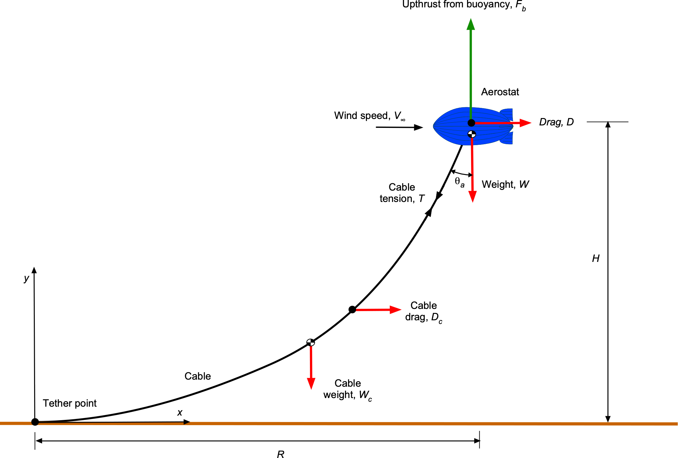


 , which then sags under its own weight
  per unit length. Assuming the cable is anchored at the origin
  and stretches to point
  at the aerostat, the general mathematical form of the catenary curve is
 and
and  are constants of integration determined by these boundary conditions. Notice that the symbol cosh denotes the
  ,
,  , so
, so


 is the inverse hyperbolic sine function.
 is used, i.e.,


 of the aerostat above the ground. Then the tether angle at the aerostat,
  , can be determined from the slope of the catenary at

 , is zero. The foregoing equations are simplified if the drag on the cable,
  , is assumed to be small compared to the drag on the aerostat, which is reasonable for shorter cable lengths and lower wind speeds.


 , for the aerostat can be estimated based on the Hoerner formula for a prolate spheroid in Eq.


 slug ft
 .
.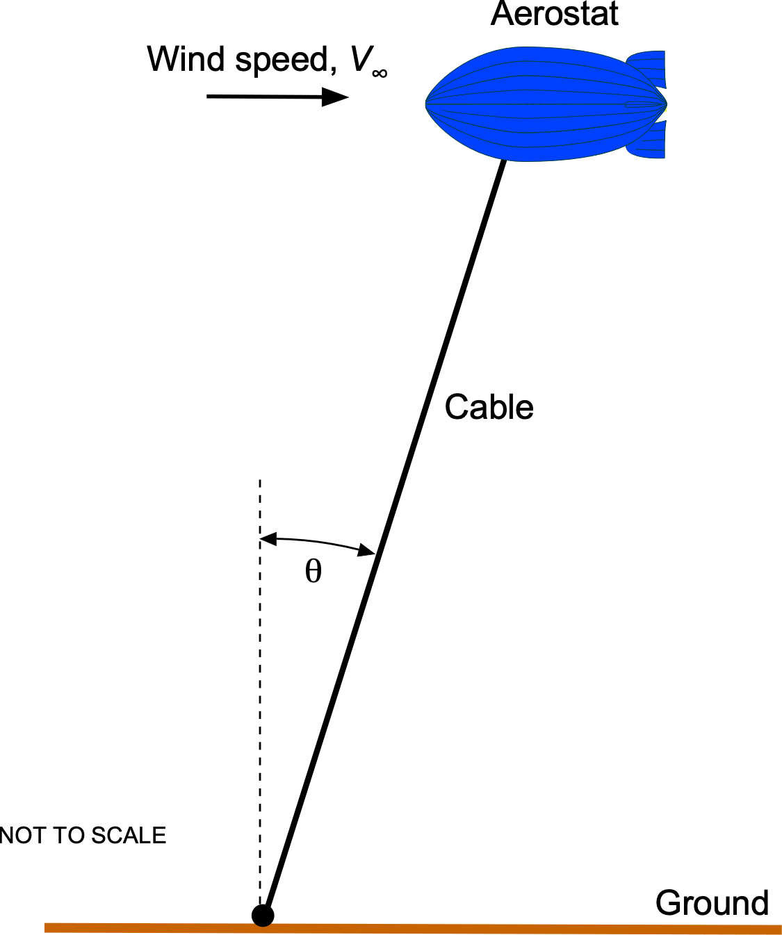
![\[ F_b = W_a + W_c + T \cos \theta \]](https://eaglepubs.erau.edu/app/uploads/quicklatex/quicklatex.com-e96fa7987cbba3fdc1c404e2cb9d233b_l3.svg "Rendered by QuickLaTeX.com")
![\[ T \cos \theta = F_b - W_a - W_c \]](https://eaglepubs.erau.edu/app/uploads/quicklatex/quicklatex.com-08dd664dbca75fbdfc3355445491cebd_l3.svg "Rendered by QuickLaTeX.com")
 is the weight of the aerostat, and
  is the weight of the cable.
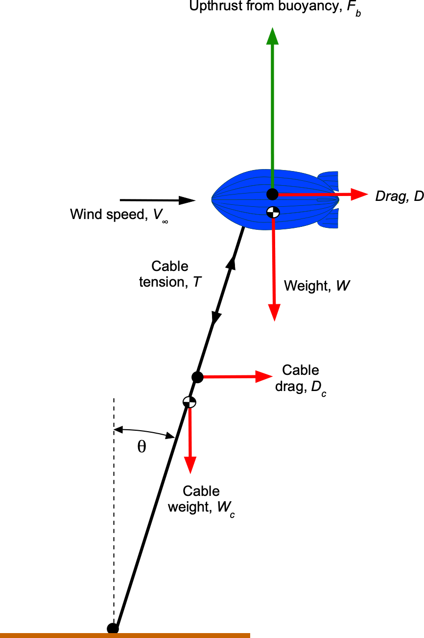
![\[ T \sin \theta = D \]](https://eaglepubs.erau.edu/app/uploads/quicklatex/quicklatex.com-54b668afc6f379fe39209696238f2fc8_l3.svg "Rendered by QuickLaTeX.com")
![\[ F_b = \varrho_{\rm air} {\cal{V}} g - \varrho_{\rm He} {\cal{V}} g = \left( \varrho_{\rm air} - \varrho_{\rm He} \right) {\cal{V}} g \]](https://eaglepubs.erau.edu/app/uploads/quicklatex/quicklatex.com-97cd55277b3e5002c636155749e47cf6_l3.svg "Rendered by QuickLaTeX.com")
 , on the aerostat is given by
![\[ D = \frac{1}{2} \varrho_{\rm air} \, V_{\infty}^2 \, A_{\rm ref} \, C_D \]](https://eaglepubs.erau.edu/app/uploads/quicklatex/quicklatex.com-90ad557f23c806df60b7e89771b3f303_l3.svg "Rendered by QuickLaTeX.com")
![\[ \frac{T \sin \theta}{T \cos \theta} = \frac{ D}{F_b - W_a - W_c} = \tan \theta \]](https://eaglepubs.erau.edu/app/uploads/quicklatex/quicklatex.com-565c37183b0e6ecb48f60ec6e99339bd_l3.svg "Rendered by QuickLaTeX.com")
![\[ \tan \theta = \frac{\displaystyle{\frac{1}{2} \varrho_{\rm air} V_{\infty}^2 A_{\rm ref} \, C_D}}{\left( \varrho_{\rm air} - \varrho_{\rm He} \right) {\cal{V}} \, g - W_a - W_c} \]](https://eaglepubs.erau.edu/app/uploads/quicklatex/quicklatex.com-8b41c0ef15bcdfaad904237027da6a05_l3.svg "Rendered by QuickLaTeX.com")
![\[ \tan \theta = \frac{\displaystyle{\frac{1}{2} \times 0.0022 \times (25.0 \times 1.688)^2 \times \left( \frac{\pi \, 38.0^2}{4} \right) \times 1.2}}{\left( 0.0022 - 0.000319 \right) \times 200,000 \times 32.17 - 4,200 - 4,000 \times 0.25} \]](https://eaglepubs.erau.edu/app/uploads/quicklatex/quicklatex.com-b37988055ea3e278df7cd5c3f8ec42b1_l3.svg "Rendered by QuickLaTeX.com")
![\[ \tan \theta = \frac{1,493.65}{6.899.87} = 0.2165 \]](https://eaglepubs.erau.edu/app/uploads/quicklatex/quicklatex.com-bc876df5dfa8d85345de9d4d3053eb1d_l3.svg "Rendered by QuickLaTeX.com")
![\[ \theta = \tan^{-1} \left( 0.2165 \right) = 12.3~\mbox{deg.} \]](https://eaglepubs.erau.edu/app/uploads/quicklatex/quicklatex.com-7dea7b23d47741ac526844f56b6869d4_l3.svg "Rendered by QuickLaTeX.com")