32 Wing Shapes & Nomenclature
Introduction
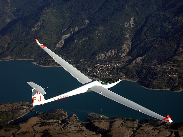
One of the most critically important parts of an airplane is, obviously, its wings. The wings primarily create the aerodynamic lift to overcome the aircraft’s weight. However, they also have movable surfaces, such as ailerons, flaps, spoilers, and trim tabs, to develop additional aerodynamic forces that control the aircraft during its flight. The photograph below shows a view of the wing of an airliner, which is not only a marvel of aeronautical engineering but also aesthetically beautiful. Its refined aerodynamic design slices through the air almost effortlessly, its sleek form and intricate mechanical functionality captivating both aeronautical engineers and passengers alike.

Wings are geometrically defined in terms of their span (distance from wing tip to wing tip), planform (their shape in outline looking down on the wing from above), twist (pitch angle) distribution, and cross-section (i.e., airfoil section shape or profile shape). The shape of a wing must be engineered to achieve good aerodynamic efficiency in lift production while minimizing drag, thereby maximizing the lift-to-drag ratio —a fundamental goal in aerodynamic design. However, other aerodynamic requirements will always factor into the wing design, including its low-speed flight, high angle of attack, and stalling characteristics.
In addition to the preceding, the wing structure must be strong enough and stiff enough to carry all the aerodynamic, weight, inertial, and other loads acting on the wing. Therefore, the wing must be structurally designed and tailored to minimize weight while resisting all stresses and meeting other structural load requirements. Examples include:
- Minimizing the loads and deformations of the wing under the action of the aerodynamic forces and moments.
- Avoiding the onset of adverse structural bending, twisting, or other aeroelastic effects and flutter.
- Carrying undercarriage loads or other point loads such as engines and various inertial loads produced during maneuvers, etc.
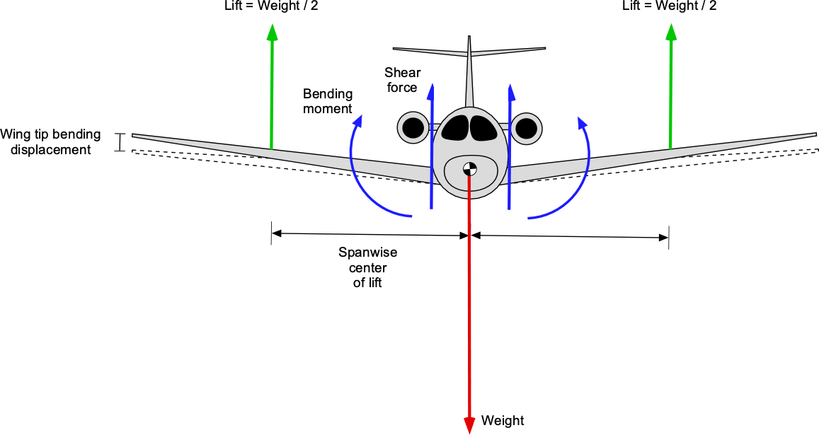
The wings carry the entire weight of the aircraft, so large shear loads and bending moments are produced near the root of the wing. To this end, the wing shape typically needs to be significantly larger in chord and thicker in cross-section near the fuselage than at the wing tips to achieve the required structural strength and stiffness. While airplane wings are enormously strong, they are still limited in what they can achieve aerodynamically and structurally.
Learning Objectives
- Know the critical geometric parameters used to define the shape of a wing.
- Be able to calculate the wing area and aspect ratio of an arbitrary wing planform.
- Understand the significance and use of mean wing chords.
- Gain an appreciation of winglets and how they work.
Geometric Definition of a Wing
Engineers use various geometric parameters to describe the shapes of wings. Terms such as span, chord, mean chord, aspect ratio, and sweep angle are used routinely in wing design, and it is essential to understand what these terms mean. Other terms used in wing design include the wing’s twist or wash-out, the planform taper ratio, the dihedral or anhedral, and the wing section thickness-to-chord ratio.
Wing Span & Semi-Span
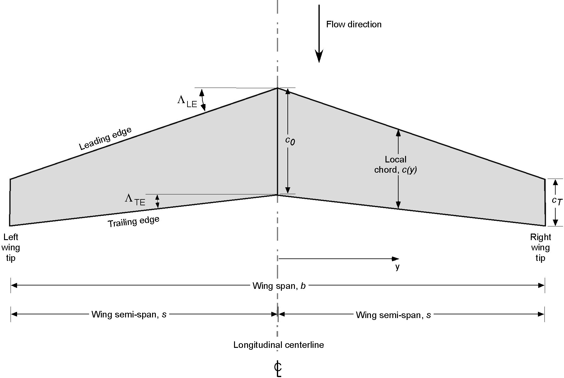
The span of the wing, or wing span, given the symbol  , is defined as the distance from one wing tip to the other (for now, the effect of a winglet will not be considered), as shown in the figure below. Sometimes, the semi-span is used to define the wing in engineering analysis, given the symbol
  and equal to
  . The usual assumption is that the right and left wing panels are geometrically and aerodynamically mirror images of each other. Notice that the symbol
  in the figure below means the centerline of the wing or aircraft.
Wing Chord and Planform
The wing chord is the distance from its leading edge to its trailing edge in the streamwise direction, i.e., parallel to the airplane’s longitudinal axis. The chord is given the symbol  . On many airplanes, the chord changes along the wing’s span, i.e.,
  as in the above figure, mainly for aerodynamic reasons. A primary aerodynamic goal for the wing is to minimize drag for a given amount of lift, i.e., to maximize the lift-to-drag ratio, which is an aerodynamic efficiency metric for a wing.
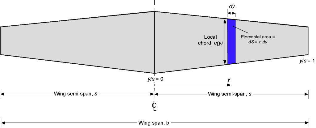
The shape of the wing is defined in terms of the chord distribution along the span of the wing, and when the wing is viewed from above, the resulting shape is called the planform. Suppose  is measured from the longitudinal centerline of the aircraft (i.e., not the wing root), as shown in the figure below. In that case, the local value of the wing chord can be expressed as
 , where
  at the centerline of the aircraft and
  at the wing tip. The wing chord can also be expressed in terms of the non-dimensional span where
  at the wing centerline and
  at the wing tip.
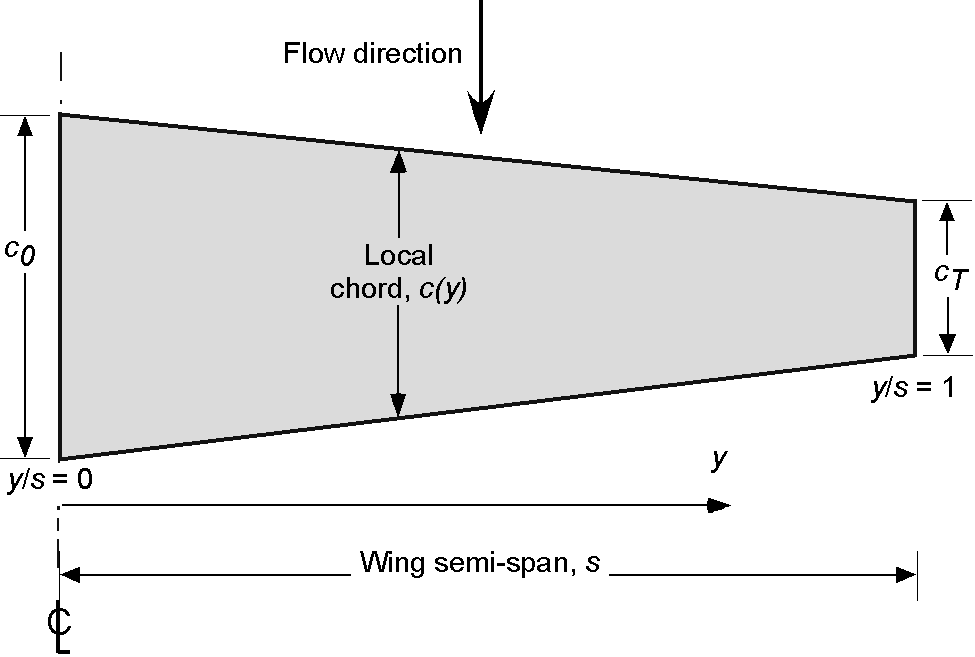
Wings are often linearly tapered in planform, for good engineering reasons, with different values of the root chord  and the tip chord
  . Many airplanes have been designed with linearly tapered wing shapes. They offer a good compromise between weight and structural efficiency, enhancing aerodynamic performance by reducing induced drag and improving fuel efficiency.
In this case, the linear taper ratio of the wing can be defined as
(1) 
For a linearly tapered wing, as shown in the figure above, the chord distribution along the wing will be
(2) 
The taper ratio may also be used to quantify the average taper of the wing planform in cases where the wing is not precisely linearly tapered.
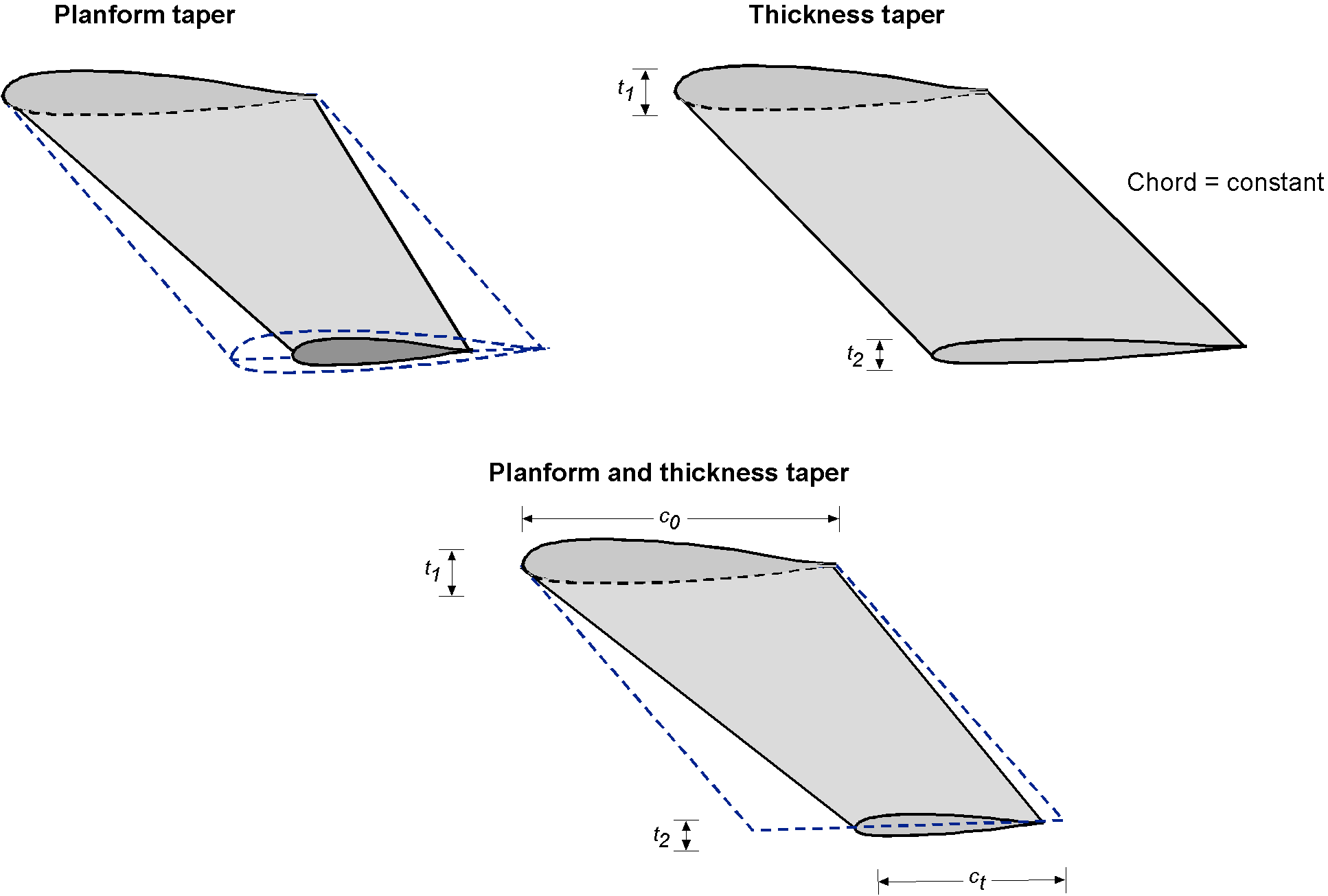
Wings may not only taper in planform but also in thickness or, indeed, as combinations of taper and thickness, as shown in the figure below. Using both taper and thickness together provides considerable engineering latitude in tailoring the wing’s shape to meet a given level of aerodynamic performance, while minimizing structural loads and weight. A further aerodynamic advantage may be gained by using different airfoil sections along the span, e.g., using a relatively thin airfoil section at the wing tip for low drag, where the structural loads are lower, and thicker airfoils further inboard, where resisting structural loads is a more important consideration.
The use of inverse wing taper is unusual, i.e., the chord increases toward the wing tip. However, it has been used to address the problem of adverse stall characteristics and a tendency to spin, a common issue in the first generation of jet aircraft with swept wings. The sweepback of the wing encourages a spanwise flow, making the wing tips more likely to stall first and reducing the effectiveness of the ailerons. However, besides increasing wing weight and roll inertia, this latter approach was unsuccessful, and other (and simpler) methods were more effective in mitigating the stall problem with swept wings.
Sweepback
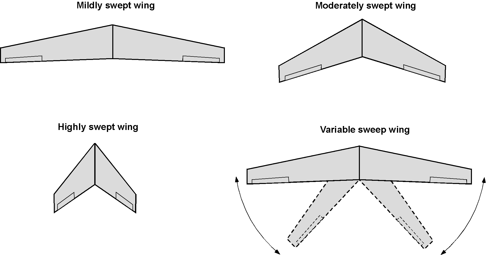
Today, many airplanes have wings with sweepback, as shown in the figure below; however, some lower-performance airplanes may have no sweepback. The primary aerodynamic purpose of sweepback on a wing is to delay the onset of compressibility effects and the buildup of wave drag at higher flight Mach numbers, and/or to reduce drag at a given Mach number, thereby decreasing the propulsive thrust and fuel required for flight.
Aerodynamically, the flight Mach number component perpendicular to the wing’s leading edge primarily affects lift and drag, assuming that the Mach number parallel to the leading edge does not contribute, a principle often referred to as the independence principle. Thus, for aerodynamic analysis, the freestream Mach number, that is, the flight Mach number of the aircraft, is resolved into components normal and parallel to the wing’s leading edge based on the local sweep angle. Wings can also be swept forward to obtain the same effect. However, a problem with a forward-swept wing is that it is aeroelastically unstable and tends to twist nose-up under the action of aerodynamic loads, so forward sweep is rarely used.
Aircraft designed for sustained supersonic flight inevitably have much higher sweepback angles than subsonic airplanes; the best planform shape for supersonic flight approaches a classic “Delta” shape. However, the use of sweepback can have other effects on the aerodynamics of the wing and the airplane, including adverse stall and low-speed handling characteristics; therefore, as little sweepback as possible is usually used. Sweepback also tends to increase the lateral stability of the airplane. Some aircraft, such as the B-1 bomber, may have variable sweepback to optimize flight aerodynamics. Still, there is a significant structural weight penalty with such “swing-wing” designs, which will be at the expense of useful load, i.e., fuel and/or payload.
The sweepback angle is often defined by the angle made by the location of the 1/4-chord points along the span of the wing, i.e.,  or it may be alternatively defined by the leading edge and trailing edge angles, i.e., by the values
  and
and  , respectively. Wings may also be designed in parts with two different sweepback angles: one sweepback angle for the inboard wing panel (usually the smaller angle) and another (larger) angle for the outboard wing panel.
Wing Twist
Wings may also be slightly twisted in terms of their angle relative to the flow along their span; one purpose of wing twist is to help give the desired distribution of aerodynamic forces over the span. In practice, most wings are twisted in some form, often subtly. It is known from aerodynamic theory and practice that the spanwise form of the lift distribution is critically important in reaching the goal of minimizing induced drag. While the spanwise lift distribution is strongly affected by wing planform (i.e., the wing chord distribution), the additional use of wing twist can help to tailor the wing lift distribution to obtain the desired aerodynamic effects.
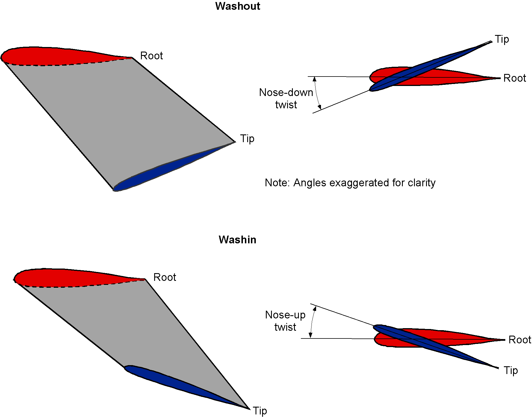
Most wings are twisted nose-down from root to tip, i.e., the pitch angles change from wing section to section and become increasingly negative toward the wing tip. This effect is called “washing out” the wing twist, and is therefore referred to as wash-out. Typical wash-out values on a wing are between 0 and 10 degrees nose-down, anything more than this being somewhat unusual. The wash-out may vary in value along the wingspan, i.e., a more significant wash-out at the wing tip than at its root.
Although very unusual for an airplane, it is called a wash-in if a wing is twisted nose-up by increasing its twist from the root to the tip along its span. One notable example was the X-29, which featured a wash-in twist on its forward-swept wings to control its adverse stall characteristics. Interestingly, some helicopter blades utilize wash-out and wash-in techniques, with the wash-in twist component applied over the blade tip region to prevent the tips from producing negative lift at higher forward airspeeds. Aerodynamic twist can also be incorporated into the wing design by changing the shape of the airfoil section, i.e., the angle of attack at which the section produces zero lift, which manifests similarly to what would be obtained by using geometric twist to change the local pitch angle of the wing relative to the flow.
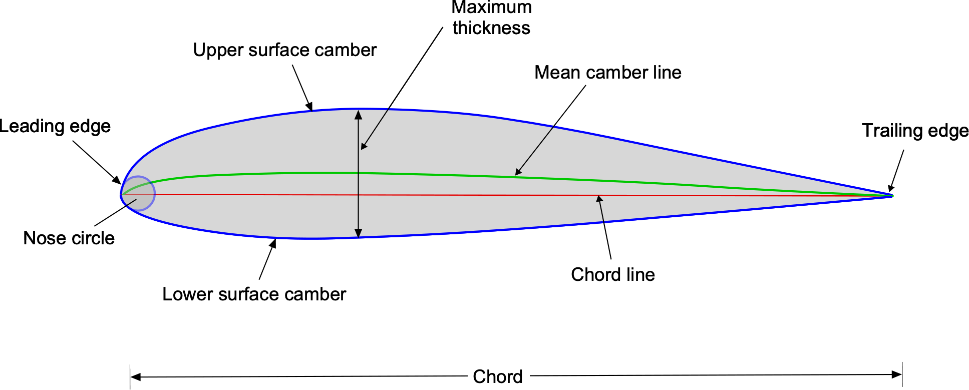
Airfoil Sections
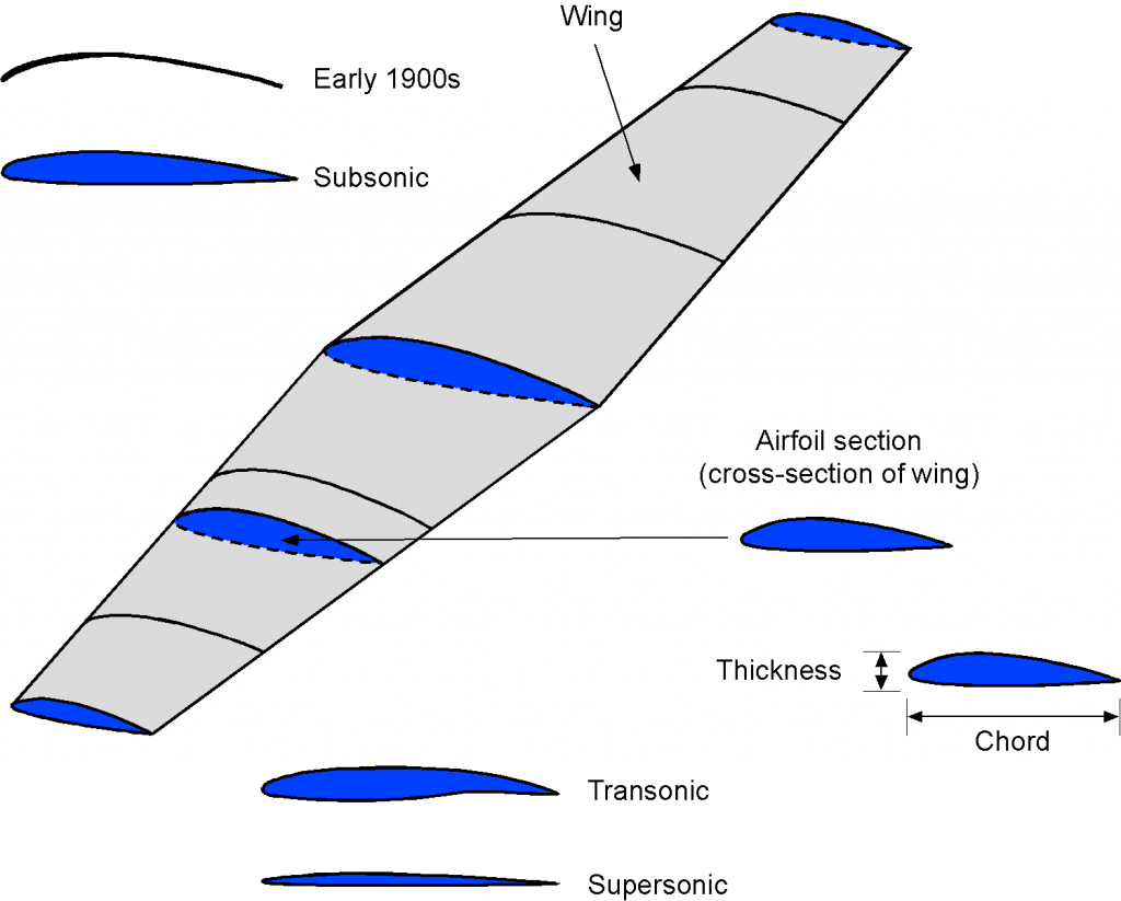
Wings can use various types and distributions of airfoil sections to suit the aircraft’s application. By cutting a slice out of an airplane wing and viewing it from the side, the wing’s cross-section is obtained, which is usually referred to as an airfoil section or profile. An example is shown below. The shape of airfoil sections can be described using camber, thickness, and nose radius as primary geometric parameters. Outside the U.S., wing sections are typically referred to as “aerofoils.”
In the evolution of wings, airfoil sections have progressed from simple, curved, plate-like shapes with minimal thickness, inspired by birds’ wings, to sophisticated shapes with camber and thickness that provide high lift and low drag. Airfoils used on subsonic airplanes are typically relatively thick and feature camber, as illustrated in the figure below. Meanwhile, the airfoils used in high-speed or supersonic aircraft are thinner, have a small leading-edge radius, and exhibit slight camber. Notice that “thickness” usually means the section’s maximum thickness-to-chord ratio. Hence, it measures how thick the wing section is relative to its chord, i.e., thickness/chord, which is usually quoted in percent. Therefore, a thickness-to-chord ratio of 0.12 would mean an airfoil that was 12% thick.
Most wings utilize different airfoils along their span, which can be progressively blended to create an overall wing design that is superior to what could be achieved using a single airfoil. This latter approach is often necessary with large commercial aircraft. As shown in the figure below, the need for significant thickness to carry the bending and shear loads at the wing’s root makes the airfoil design for low drag at higher flight Mach numbers rather challenging, primarily when the wing operates in transonic flow. The designer can utilize thinner airfoils, better suited to high-speed flight and transonic flow conditions, at the wing tips, where there are lower bending moments and structural stresses. Even on low-performance airplanes, there can be significant aerodynamic and performance advantages in using different airfoils at the wing root compared to the wing tip sections.
Airfoil section shapes may also introduce an aerodynamic twist along the wing span. Different cambered airfoils inevitably have different zero-lift angles of attack (although they may differ only by a degree or two at most), so other airfoils with different camber can be used to effectively twist the wing aerodynamically. The effects obtained are typically combined with a geometric twist to achieve the desired spanwise lift distribution, thereby meeting the aerodynamic performance and other objectives.
It is also known that using wing twist is particularly helpful in controlling the stall developments on the wing, especially in preventing the wing tips from stalling. Therefore, tailoring the wing twist distribution and, to some extent, the airfoil sections allows the designer to have some latitude in satisfying the low-speed handling qualities of the airplane. It is not unusual for newly designed airplanes to have the airfoils over the outer wing panels changed[1] after their first flights to meet the stalling and handling qualities requirements needed for certification. However, other methods may be required to control the airplane’s stall characteristics.
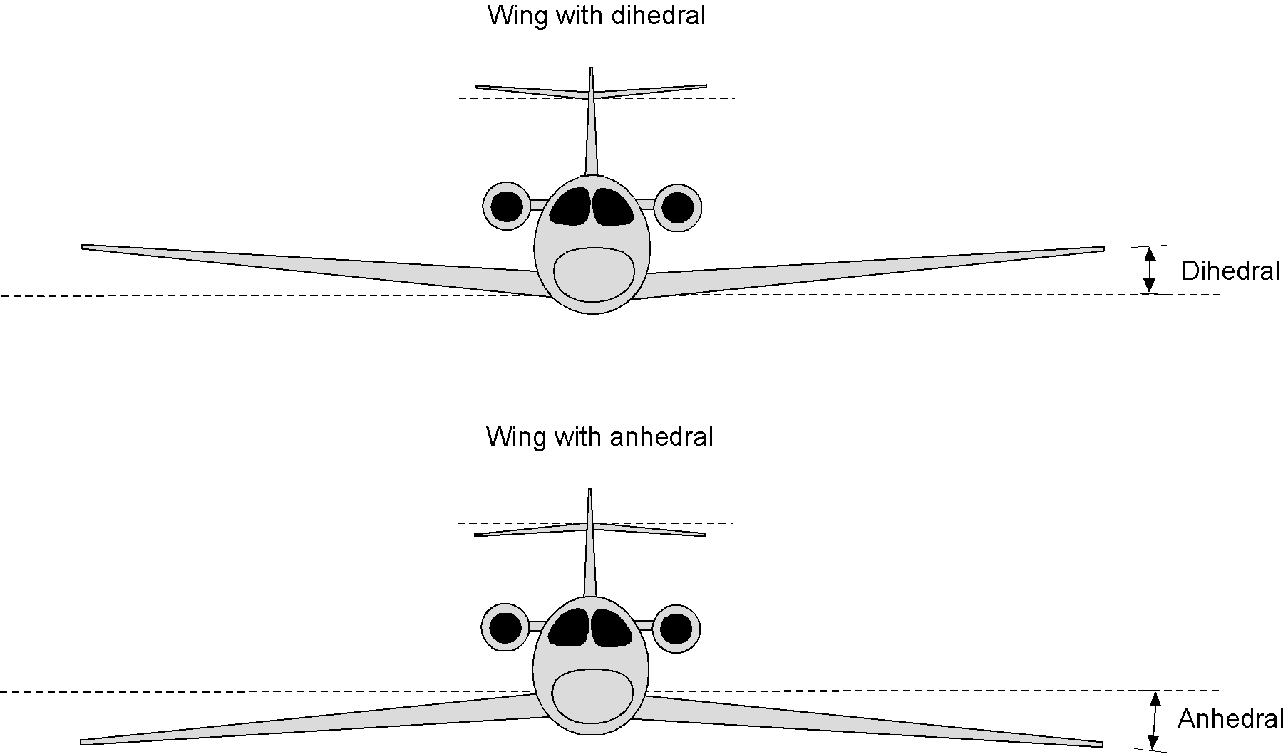
Dihedral & Anhedral
The dihedral angle is the upward angle the wing panels make relative to the aircraft’s reference axis, as shown in the figure below. Its primary purpose is to improve the aircraft’s lateral (roll) stability; usually, only a few degrees are needed to significantly enhance stability. The horizontal tail may also exhibit some dihedral, particularly on larger aircraft, which contributes somewhat to lateral stability. Some dihedral will come from wing-bending structural displacements.
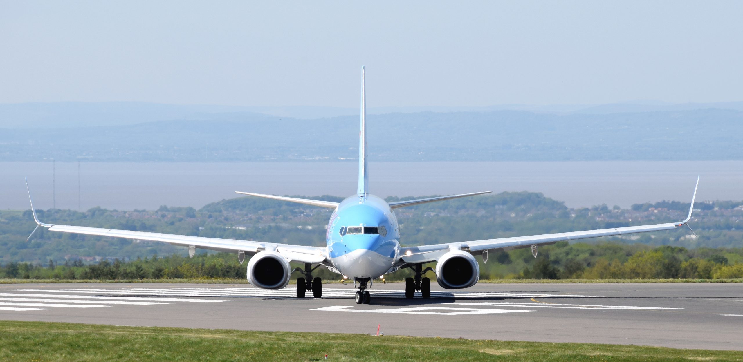
The photograph below shows an example of the use of dihedral on a Boeing 737. Notice that the main wing and horizontal tail both have a notable amount of dihedral. Good lateral stability is desirable for most aircraft, especially airliners, so passengers experience a smooth and comfortable ride through turbulence.
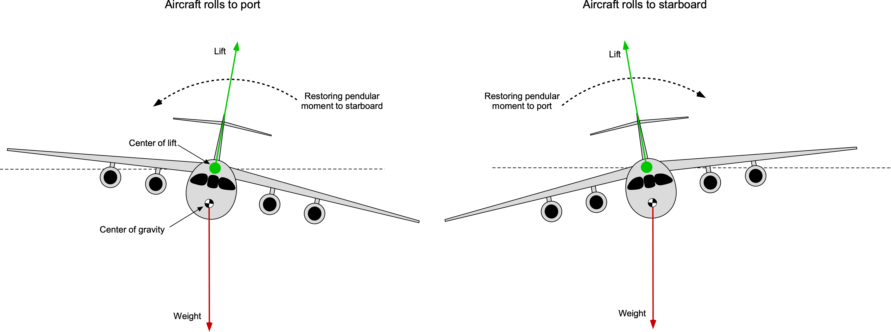
A downward wing angle is called anhedral and is somewhat less common on airplanes without wing sweepback or a high wing design, as it decreases roll stability. However, airplanes with swept wings may use anhedral to offset the increase in roll stability from using sweepback. Airplanes with high-mounted wings also tend to exhibit significant pendular lateral stability because the center of gravity lies below the center of lift, as illustrated in the figure below. The center of lift can be assumed to be the aerodynamic “pivot” point. In this case, anhedral on the wing is needed so that lateral stability is not too strong, making the aircraft difficult to turn and maneuver.
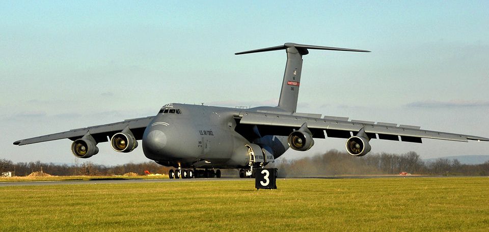
An example of a wing with anhedral is found on the C-5 Galaxy military transport aircraft, as shown in the photograph below. The C-5 needed to have the fuselage and loading deck as close to the ground as possible, so the only design choice for this aircraft was a high wing with anhedral. While lateral stability (and stability, in general) is generally good, excessive stability can make the aircraft less maneuverable and agile, resulting in overall handling qualities that suffer, i.e., the aircraft becomes sluggish in response to control inputs. Sweepback on the wing, which is used to delay the onset of compressibility effects, can also introduce specific undesirable flight dynamic characteristics, which can be offset using anhedral.
Calculation of Wing Area
Several derived geometric characteristics of wings, including the wing area, aspect ratio, and mean chord, are important in engineering analysis. The planform area of the wing, which is given the symbol  , is obtained by integrating the distribution of the wing chord along the span from one wing tip to the other, i.e.,
(3) 
where , as shown in the figure below.
If both wings are of the same geometry, i.e., symmetrically disposed with respect to the longitudinal axis along the fuselage, and so are mirror images of each other (which is the case on nearly all airplanes), then
(4) 
Of course, a dilemma arises here, and a question to ask is whether the wing area refers to the actual area of the wing exposed to the airflow or something else. In the above equation, the former has been assumed, and the value of the area, , is called the planform area or wing reference area.[2] However, there can be circumstances when the actual area of the wing exposed to the flow needs to be known, called the wetted area, in which case the lower limit of integration would be adjusted accordingly to start from the side of the fuselage. Therefore, it is essential to verify the actual definition(s) of the wing area used in different types of engineering analysis.
Calculation of Aspect Ratio
The aspect ratio of the wing, which is given the symbol  , is defined as the ratio of the square of the wing span to the wing reference area, i.e.,
(5) 
The aspect ratio of a wing is crucial in aerodynamic analysis because a wing with a higher aspect ratio is generally more aerodynamically efficient and has lower drag.
Every aircraft design will have a somewhat different wing aspect ratio. However, typical values range from 5 to 10 for a small general aviation aircraft, 9 to 15 for a commercial transport aircraft, and 30 and higher for a glider (sailplane). As a point of reference, the Rutan Voyager airplane in 1986 flew around the World without refueling,[3]had a wing aspect ratio of 34, which is unusually high for an aircraft other than a sailplane.
It will be apparent that the aspect ratio of a wing is a physical measure of the geometric slenderness of the wing. The easiest way to understand this is to assume a wing of a constant chord, i.e.,  constant. In this case, then
(6) 
where  and so
(7) 
which is just the ratio of the wingspan to the chord. Therefore, a wing with a higher span and a narrower chord will have a higher aspect ratio. Hence, the numerical value of the aspect ratio becomes a measure of the slenderness of the wing.
However, the aspect ratio must be calculated using the exact wing planform; most wings will not have rectangular planforms, so the aspect ratio must be calculated by using the wing chord distribution and resulting area, i.e., using the formula
(8) 
In some cases, the wetted aspect ratio may be specified, which uses the wetted wing area rather than the reference wing area; however, this is rare.
Check Your Understanding #1 – Finding the planform area & aspect ratio of a wing
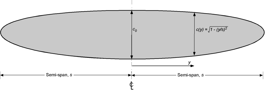
The wing of a Supermarine Spitfire has an elliptical wing planform with a root chord of 100 inches and a span of 445 inches. Calculate the planform area and aspect ratio of its wing.
Show solution/hide solution.
The chord for an elliptical wing planform shape can be expressed as
![\[ c(y) = c_0\sqrt{ 1 - \left( \frac{y}{s} \right)^2 } \]](https://eaglepubs.erau.edu/app/uploads/quicklatex/quicklatex.com-36094d8560dc471cd0d3e8a36c8b3eef_l3.svg "Rendered by QuickLaTeX.com")
where is the root (centerline) chord. The planform area of the wing, , is
![\[ S = 2 \int_{0}^{s} c \, dy \]](https://eaglepubs.erau.edu/app/uploads/quicklatex/quicklatex.com-6a377f9e0f7e94ba5453a6fcea358525_l3.svg "Rendered by QuickLaTeX.com")
and substituting for the chord distribution gives
![\[ S = 2 \int_{0}^{s} c_0\sqrt{ 1 - \left( \frac{y}{s} \right)^2 } \, dy = 2 c_0 \int_{0}^{s} \sqrt{ 1 - \left( \frac{y}{s} \right)^2 } \, dy \]](https://eaglepubs.erau.edu/app/uploads/quicklatex/quicklatex.com-a300da4efb6356e97b49fe4d7ef7fd72_l3.svg "Rendered by QuickLaTeX.com")
This is a standard integral, so
![\[ S = 2 c_0 \left[ \frac{1}{2} \left( y \sqrt{1 - \frac{y^2}{s^2} } + s \sin^{-1} \left( \frac{y}{s} \right) \right) \right]_0^s \]](https://eaglepubs.erau.edu/app/uploads/quicklatex/quicklatex.com-71367c1ff5d583f606b891d761c26602_l3.svg "Rendered by QuickLaTeX.com")
or
![\[ S = c_0 \left[ y \sqrt{1 - \frac{y^2}{s^2} } + s \sin^{-1} \left( \frac{y}{s} \right) \right]_0^s = \frac{\pi c_0 s}{2} \]](https://eaglepubs.erau.edu/app/uploads/quicklatex/quicklatex.com-071249a3f39fc12ada7d78167bead926_l3.svg "Rendered by QuickLaTeX.com")
Therefore, the planform area of this wing is
![\[ S = \frac{\pi c_0 s}{2} = \frac{ \pi \times (100.0/12.0) \times (445/2/12)}{2} = 242.71~\mbox{ft${^{2}}$} \]](https://eaglepubs.erau.edu/app/uploads/quicklatex/quicklatex.com-09b30db3cfcdda9e78bd418ae067cc83_l3.svg "Rendered by QuickLaTeX.com")
and the aspect ratio, , is
![\[ A\!R = \frac{b^2}{S} = \frac{4s^2}{S} = \frac{4 \times (445/2/12)^2}{242.71} = 5.67 \]](https://eaglepubs.erau.edu/app/uploads/quicklatex/quicklatex.com-705f3f94f0e487c21613b37235aa3ba4_l3.svg "Rendered by QuickLaTeX.com")
The aspect ratio of a wing on an airplane can be increased by increasing the wing span and decreasing the wing chord, as shown in the figure below; this example also maintains a constant wing area. The aerodynamic advantage in doing so is a significant reduction in induced drag because the wing tip vortices (the source of this type of drag) are further away from more of the wing. However, as the aspect ratio of a wing increases, it becomes more challenging to design the wing to have sufficient stiffness and strength without increasing its weight. As a result, a more extended wing is inevitably more flexible, unless some additional structure is used to stiffen it.
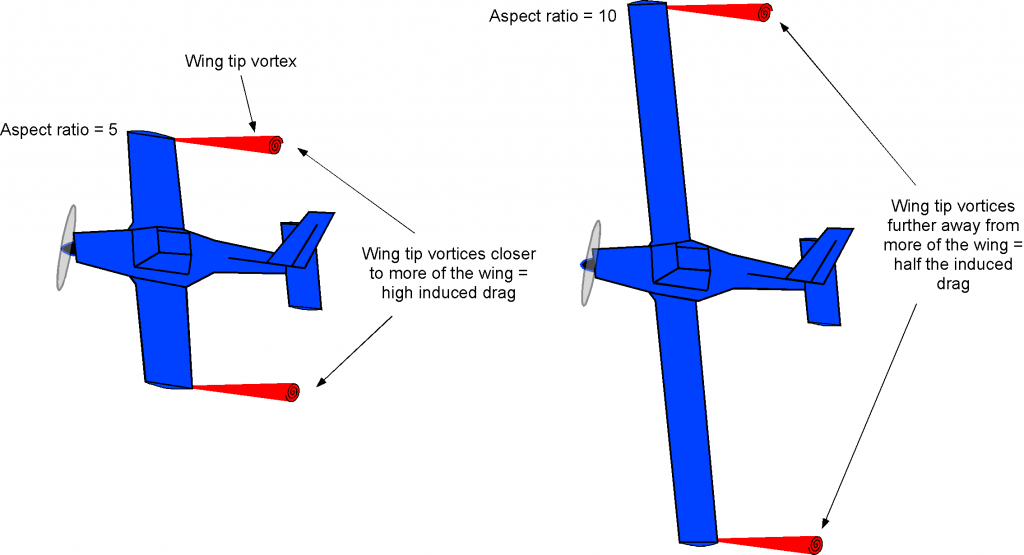
In airplane design, the final selection of the wing aspect ratio is inevitably a compromise between aerodynamic, structural, weight, and aeroelastic considerations. Longer wings are also heavier and more susceptible to flutter problems because they are inevitably more flexible. Nevertheless, there are tremendous aerodynamic advantages to using a wing with the highest possible aspect ratio, provided all the structural, weight, flutter, and other requirements for the airplane can be satisfied.
Airplanes come in many shapes and sizes, utilizing wings with varying aspect ratios, as illustrated in the figure below. The wing design is inevitably a compromise, which will depend on what the aircraft is designed to do in terms of its performance, weight, and cost considerations. General aviation airplanes, for example, tend to have relatively modest aspect ratio wings, which gives a good compromise between adequate aerodynamic performance and low structural weight.
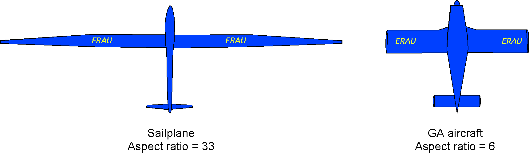
Sailplanes, which are high-performance gliders, typically have wings with a very high aspect ratio compared to those of powered aircraft. Thus, they can achieve high lift-to-drag ratios and glide long distances by design. The DG-800 in the photograph below exemplifies a modern sailplane with an aspect ratio of just over 27. These types of sailplanes can glide more than 50 miles (in still air) from an altitude of only 5,000 feet.
Calculation of Mean Chords
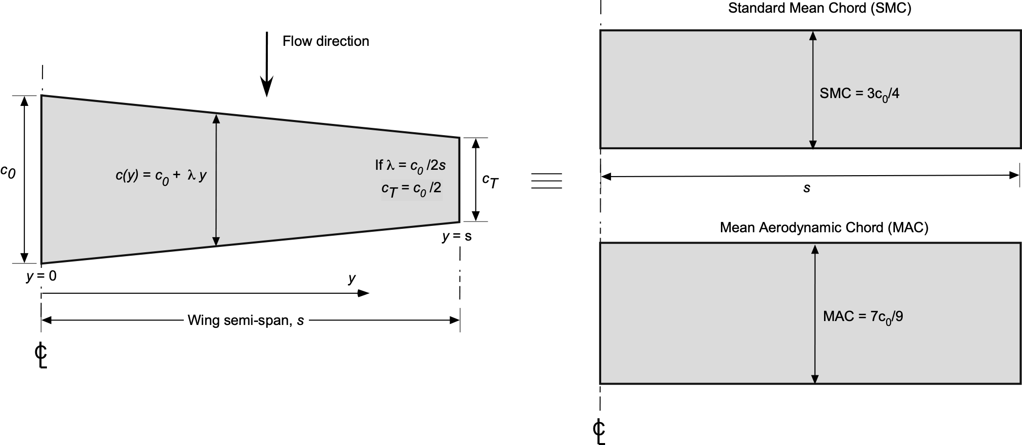
Other derived geometric parameters relevant to wings are the standard mean chord (SMC) and the aerodynamic mean chord (AMC), also called the mean aerodynamic chord (MAC). A mean chord provides a standardized length scale that can be applied across different wing geometries, shapes, and sizes. Mean chords are used in aerodynamic analyses as a reference length, such as to calculate pitching moment coefficients. For example, in aerodynamics, the moment coefficient about some point  can be expressed as
(9) 
where  is a reference length. For a wing, can be defined as either the SMC or the MAC, the use of the MAC being preferred. Mean wing chords are also used as reference lengths in other aeronautical disciplines, where certain lengths and length scales may be non-dimensionalized by using the value of the mean wing chord.
Standard Mean Chord
The standard mean chord (MAC) appears in many aerodynamic contexts. The SMC is often referred to as a “purely geometric” definition, which it is at face value. However, as will be discussed, its derivation has several “hidden” aerodynamic assumptions. These assumptions include two-dimensional flow over the entire wing and a uniform distribution of spanwise lift coefficients along the wing.
Definition
The standard mean chord (SMC), which is given the symbol  , is defined as the ratio of the wing area to the wing span, i.e.,
(10) 
where . Concerning the figure below, it will be apparent that the SMC is the chord of an equivalent rectangular wing with the same area and span that produces the same lift force. It should be noted that the wing shape is not restricted to a linearly tapered planform, as shown in the figure, and Eq. 10 is valid for any wing planform.
The work involved in obtaining the SMC value depends on the platform’s complexity, which can range from simple rectangular to more complex tapered designs. It may also involve regions with different tapers and geometrically distinct wing panels, possibly with a sweep angle. In these latter cases, the integral can be solved by finding the contribution from each part of the wing and adding them.
Derivation
The derivation of the equation for SMC proceeds by considering the elemental lift on a two-dimensional strip of the wing of area  . Only the half-wing needs to be considered, assuming that both wing panels have mirror geometric and aerodynamic symmetry.
The lift on the element is given by the usual formula, i.e.,
(11) 
where  is the local chord and
  is the local sectional lift coefficient. The total lift on the wing is then
(12) 
The total lift on the wing can also be written as
(13) 
where  , i.e., the areas of the actual wing and the equivalent rectangular wing are equal. (Remember that is the semi-span of the wing, and is the wing area.) Notice that
  is the wing’s total lift coefficient. Equating Eqs. 12 and 13 gives
(14) 
Making the aerodynamic assumption that  = , i.e., the local lift coefficient is constant at all sections over the wing span and equal to the total lift coefficient, then
(15) 
which was previously defined in Eq. 10.
Therefore, while the definition of the SMC is ultimately geometric, one assumption behind its definition is that the wing comprises two-dimensional airfoils with a uniform lift coefficient across the span. However, despite arguments about the validity of the aerodynamic assumptions, it does not matter because the SMC is simply a definition used as a reference standard. To this end, the SMC is helpful for many purposes because it allows the comparison of wings and their aerodynamic characteristics on a common basis. For this reason, all engineers subscribe to the same definition of the SMC.
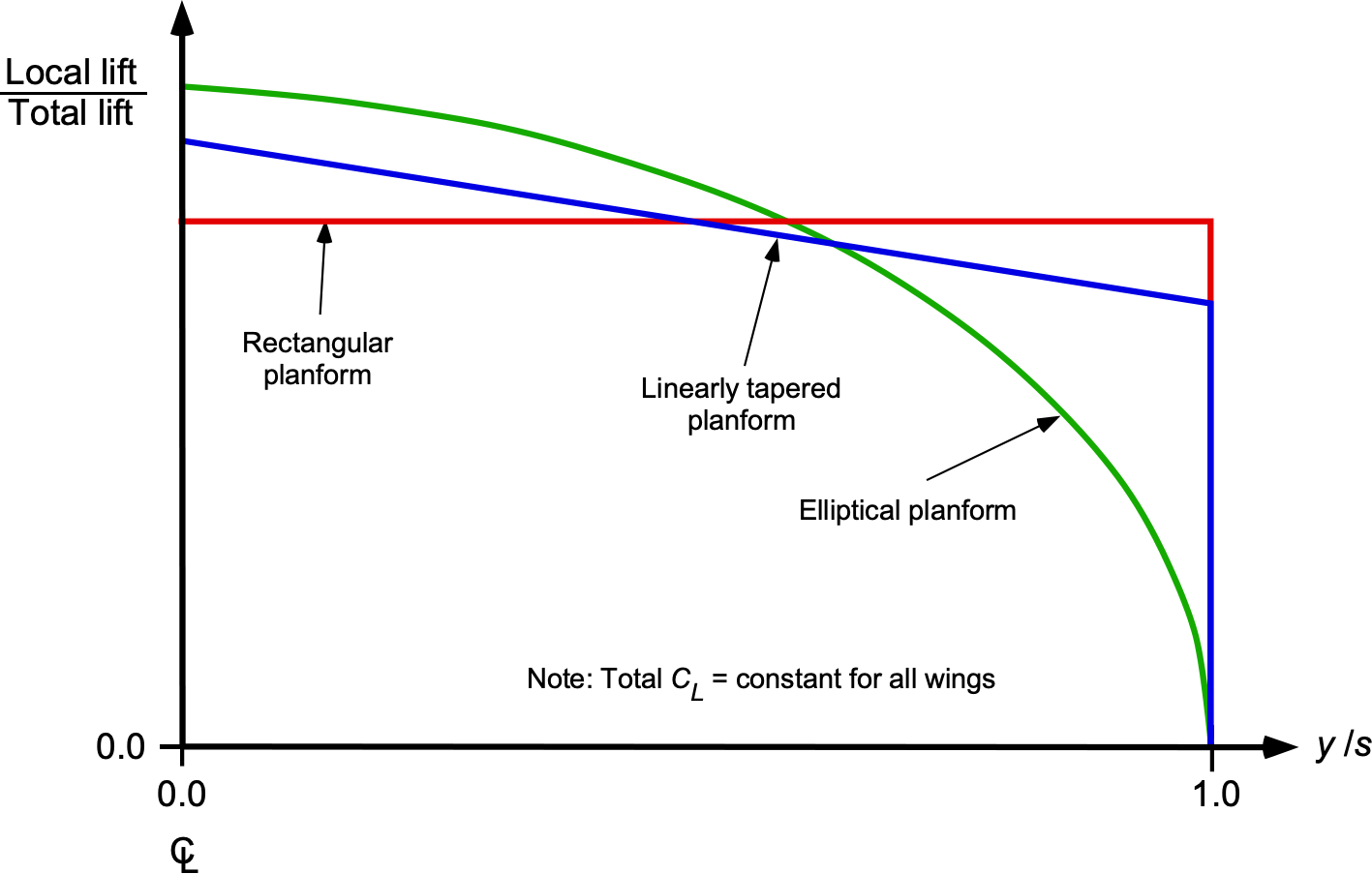
Because the lift per unit span is
(16) 
then it will be apparent that with this assumption, the local lift force per unit span (as opposed to the lift coefficient) is proportional to the chord. Other than for the region near the wing tip, where there are three-dimensional effects, including those from the wing tip vortex, Eq. 16 provides a first approximation to the spanwise lift distribution on a wing, as shown in the figure below.
Mean Aerodynamic Chord
The mean aerodynamic chord (MAC), also known as the aerodynamic mean chord (AMC), is a term frequently encountered in aerodynamics. The AMC can be easily confused with the SMC, but they are different quantities and numerical values. Like the SMC, the MAC is often referred to as a “purely geometric” definition, which it is; however, as will be discussed, its derivation also has several assumptions.
Definition
The mean aerodynamic chord (MAC) is defined as the chord of an equivalent rectangular wing that would experience aerodynamic forces and moments identical to those of the actual wing. The MAC is defined as
(17) 
This is another type of “average” aerodynamic chord definition for the wing. It is more frequently used because, in this definition, both forces and moments on the wing are considered equivalent. Again, the work involved in finding the MAC depends on the complexity of the wing planform.
Derivation
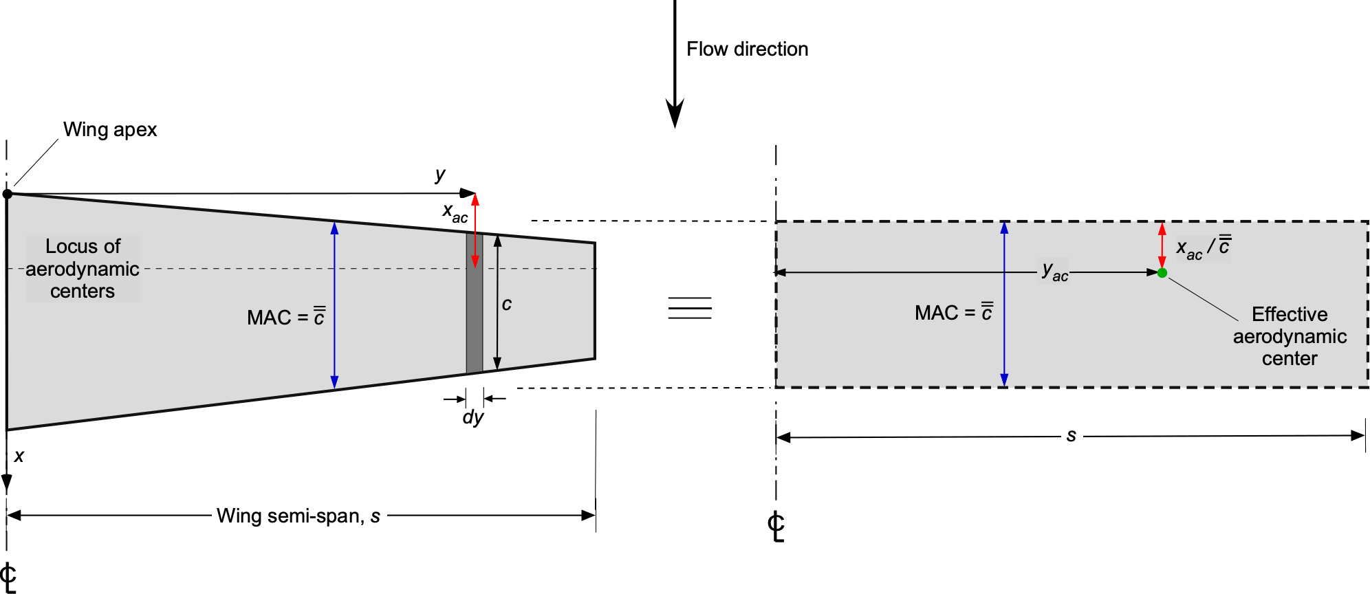
The derivation of the equation for the MAC proceeds similarly to that for the SMC. In this case, however, a pitching moment must be calculated. Regarding the figure below, which illustrates an unswept wing for simplification purposes, the locations of the aerodynamic center for each wing section lie parallel to the – axis. Notice that for a thin airfoil in an incompressible flow, the aerodynamic center is at the quarter-chord point, i.e.,  ; the aerodynamic center is a fixed point independent of
  . Again, only the half-wing needs to be considered.
For each two-dimensional strip, taking pitching moments about the spanwise axis that runs through the apex of the wing, as shown in the figure below, then
(18) 
The total pitching moment produced by the entire wing is then
(19) 
The total moment can also be written as
(20) 
where  , i.e., the areas of the actual wing and the equivalent rectangular wing are equal.
Notice in Eq. 20 that the aerodynamic center location in Eq. 20 is now expressed as a fraction of the MAC, i.e.,  . It will be apparent that in aerodynamic terms then, the value of
  as a fraction of will be identical to the value of as a fraction of , i.e.,
(21) 
which also gives the chordwise location of the center of lift on the equivalent rectangular wing. Equating Eqs. 19 and 20 gives
(22) 
Using Eq. 21 and making the same aerodynamic assumption as previously used for the SMC that  =
=  , then
(23) 
so that
(24) 
which was previously defined in Eq. 17. It will also be apparent that the lift produced on both the wing and the equivalent rectangular wing is equal because
(25) 
In general, the MAC is written as
(26) 
which is based solely on the wing geometry, despite the aerodynamic assumptions used in its derivation. Again, like the SMC, the physical justification of the aerodynamic assumptions is irrelevant because the MAC is simply a standardized definition that everyone subscribes to.
As a corollary to the preceding, the spanwise location of the center of lift, i.e., the spanwise aerodynamic center, can also be determined by taking moments about the  axis. In this case
(27) 
The total moment can also be written as
(28) 
(29) 
Therefore, using Eqs. 27 and 29, and with the same assumptions as used previously, gives
(30) 
The value of  is the effective spanwise location of the aerodynamic center. Notice that in the case of a rectangular wing with = constant, i.e.,
  , then
(31) 
which is exactly at mid-span, as expected for a uniformly spanwise loaded wing.
Notice that, in principle, the SMC and the MAC can be determined for any wing, including horizontal and vertical stabilizers. However, in all cases, the evaluation will involve spanwise integration, either analytically or numerically.[4]
The addition of constant angle sweepback angle,  , on the wing, for example, will move the locus of the chordwise aerodynamic center locations further behind the reference moment axes, adding
  to the moment arms in Eq. 19. However, it can be easily shown (again, using geometry) that relative to the equivalent rectangular wing, the chordwise location of the aerodynamic center is independent of the wing sweep angle, at least for a trapezoidal type of wing planform.
It is important to remember that mean (average) wing chords are used as reference lengths in aerodynamics and other related aeronautical disciplines. For example, as mentioned previously, the aerodynamic pitching moment coefficient for a finite wing about some point is defined as
(32)
where usually  , although in some cases
  may be used. It is important to note that the specific definition used in any application can vary.[5] In fields such as flight dynamics, the values of the quantified parameters are measured relative to a datum point or reference axis, such as the neutral point, center of gravity, etc., and are often quoted as a fraction of a mean chord.
SMC & MAC of a Linearly Tapered Wing
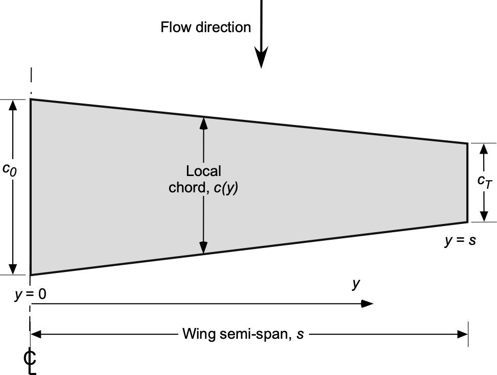
A linearly tapered wing is one of the most common wing planforms, as shown in the figure below, which is also useful for instructional purposes. It has a chord distribution that can be expressed as
(33) 
where  is a constant. Notice that when then
  (the root chord) and when
  then
then  (the tip chord).
Analysis for the SMC
The area of this wing is given by
(34) 
Performing the integration gives
(35) ![\begin{equation*} S = 2 \left[ c_0 y - \lambda \frac{y^2}{2} \right]_0^s = 2 s \left( c_0 - \frac{\lambda s}{2} \right) = s \left( 2 c_0 - \lambda s \right) \end{equation*}](https://eaglepubs.erau.edu/app/uploads/quicklatex/quicklatex.com-6b747cfbcfe0e6efb0e506a75bab2960_l3.svg "Rendered by QuickLaTeX.com")
Therefore,
(36) 
Furthermore, because  , then
(37) 
which is the combined area of the two trapezoids. Therefore,
(38) 
which is just the average of the chord over the span.
Specific Case
Consider a specific case where  then
then  , which is a trapezoidal wing planform with a 2:1 taper ratio, then
(39) 
For the SMC, then
(40) 
Therefore,
(41) 
which is the average of the root and tip chords. For a 2:1 taper where  , then
(42) 
as shown in the figure below.
Notice that because
(43) 
then the value of when  will be
(44) 
which is at the halfway point along the span. Indeed, for any uniformly linearly tapered wing panel, the value of the SMC is equal to the chord at the mid-span location.
Notice also that
(45) 
confirming that the wing with the standard mean chord has the same area as the linearly tapered wing.
Geometric Interpretation of the SMC
The value of the SMC can also be obtained geometrically (graphically), as shown in the figure below for a linearly tapered wing. This approach may provide insights not immediately evident from numerical calculations alone and can be helpful in some contexts. The process visually represents how chord lengths are distributed along the wing or airfoil and graphically finds the average geometric chord.
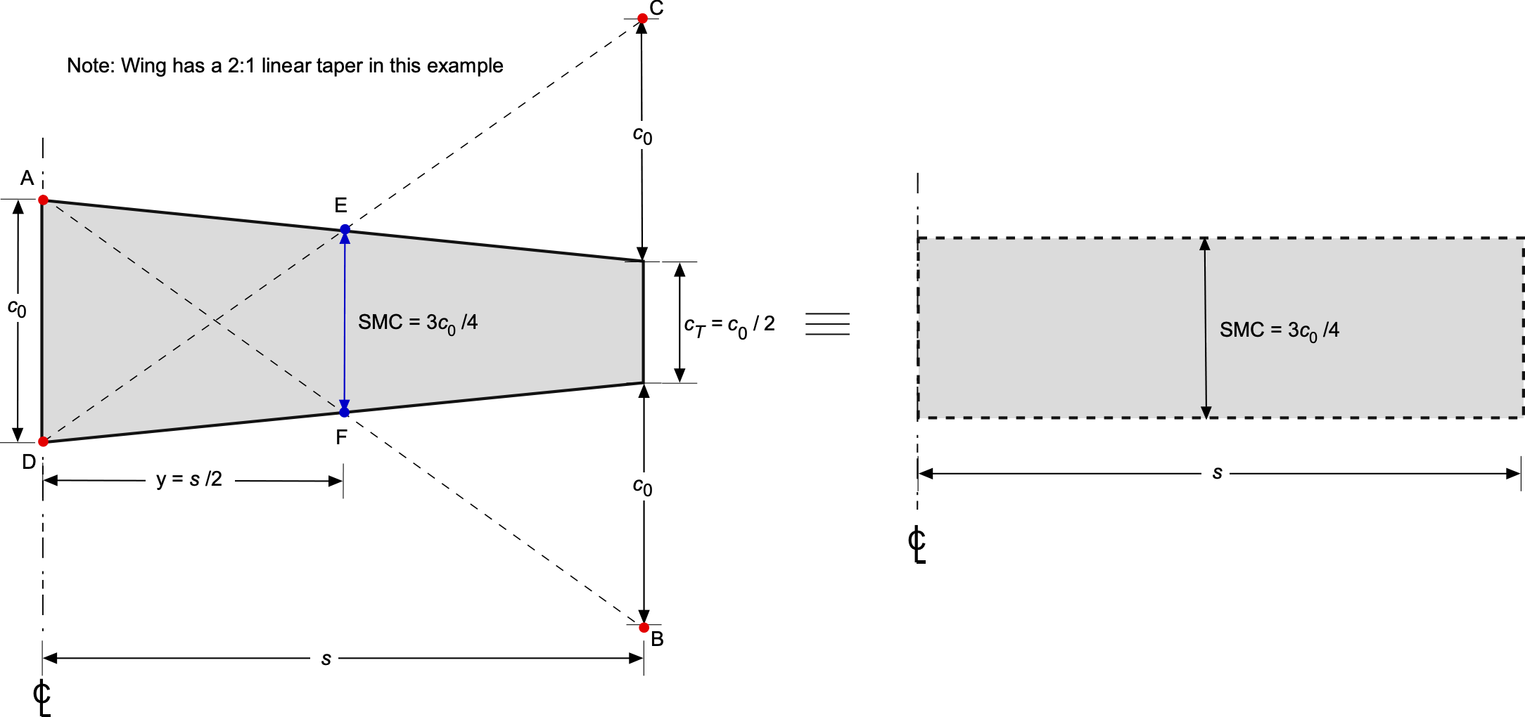
Using the principles of analytic geometry, the spanwise location and value of the SMC come about by finding the intersections between straight lines. Adding the length to the leading and trailing edges of the tip chord, as shown, gives two points at the extended wing tip, namely B and C. A straight line is drawn from the wing’s apex at point A to point D, and another straight line from the nadir (trailing edge of the root chord) at point D to point C. The intersection of these two lines with the leading edge (point E) and trailing edge (point F) of the wing panel gives the spanwise location and value of the SMC.
While a visual interpretation of the mean chord is useful, its proper value would typically be obtained analytically or numerically. Again, it should be remembered that for any linearly tapered wing panel, the SMC is always the value of the local chord at the mid-span location.
Analysis for the MAC
The MAC for this linearly tapered wing panel, which takes some more work to determine, is given by
(46) ![\begin{equation*} \overline{\overline{c}} = \frac{ \displaystyle{\int_{-s}^{s} c^2 \, dy}}{S} = \frac{ 2 \displaystyle{\int_{0}^{s} \left( c_0 - \lambda y \right)^2 \, dy}}{S} = \dfrac{ \displaystyle{ 2 \left[ c_0^2 y - c_0 \lambda y^2 +\dfrac{\lambda^2 y^3}{3} \right]_0^s }}{S} \end{equation*}](https://eaglepubs.erau.edu/app/uploads/quicklatex/quicklatex.com-9c4d61cd6d0617a9352b9801383bd76d_l3.svg "Rendered by QuickLaTeX.com")
After integration, then
(47) 
Again, take the wing planform with a 2:1 taper ratio where , then
(48) 
Check Your Understanding #2 – Finding wing parameters
A wing has an aspect ratio of 12. According to the equation below, the wing’s chord varies smoothly and continuously outward from the aircraft’s centerline. Calculate the span and planform area of this wing.
![\[ c(y) = 1 - 0.32 \left( \frac{y}{b} \right)~~\mbox{in units of meters} \]](https://eaglepubs.erau.edu/app/uploads/quicklatex/quicklatex.com-babfa2a761f3a90402b79788903dc743_l3.svg "Rendered by QuickLaTeX.com")
Show solution/hide solution.
The planform area of the wing, , is
![\[ S = 2 \int_{0}^{s} c \, dy \]](https://eaglepubs.erau.edu/app/uploads/quicklatex/quicklatex.com-523f0b0e9098b9ea0f4ab9231f808a90_l3.svg "Rendered by QuickLaTeX.com")
The chord is
![\[ c(y) = 1 - 0.32 \left( \frac{y}{b} \right) = 1 - 0.32 \left( \frac{y}{2s} \right) = 1 - 0.16 \left( \frac{y}{s} \right) \]](https://eaglepubs.erau.edu/app/uploads/quicklatex/quicklatex.com-13b03bffafba5a50a82823208a4b90cb_l3.svg "Rendered by QuickLaTeX.com")
and substituting for the chord distribution,  , gives
![\[ S = 2 \int_{0}^{s} c \, dy = 2 \int_{0}^{s} \left( 1.0 - 0.16 \left( \frac{y}{s} \right) \right) dy \]](https://eaglepubs.erau.edu/app/uploads/quicklatex/quicklatex.com-80a58440ea4ebaf540d886217adaca13_l3.svg "Rendered by QuickLaTeX.com")
so that
![\[ S = 2 \left[ 1.0 y - \frac{0.08}{s} y^2 \right]_0^s = 2(s - 0.08s) = 1.84s \]](https://eaglepubs.erau.edu/app/uploads/quicklatex/quicklatex.com-66416b7294c73392dc66d3b30ab0bf8f_l3.svg "Rendered by QuickLaTeX.com")
noting that . The aspect ratio, , is
![\[ A\!R = \frac{b^2}{S} = \frac{4s^2}{S} = \frac{4s^2}{1.84s} = 2.174 s \]](https://eaglepubs.erau.edu/app/uploads/quicklatex/quicklatex.com-0d2a625cecf11d7244a8d2cf45f25d80_l3.svg "Rendered by QuickLaTeX.com")
Therefore, solving for the span, , for an aspect ratio of 12 gives
![\[ b = 2s = 2 \left( \frac{A\!R}{2.174} \right) = \frac{2 \times 12}{2.174} = 11.04~\mbox{m} \]](https://eaglepubs.erau.edu/app/uploads/quicklatex/quicklatex.com-bc88aec45c450aef95e3820c8cd454a7_l3.svg "Rendered by QuickLaTeX.com")
The wing’s planform area is
![\[ S = 1.84 s = 1.84/b/2= 1.84 \times 5.52= 10.157~\mbox{m${^{2}}$} \]](https://eaglepubs.erau.edu/app/uploads/quicklatex/quicklatex.com-fa6df4fa01e0394c80bec8125c3338ad_l3.svg "Rendered by QuickLaTeX.com")
Winglets
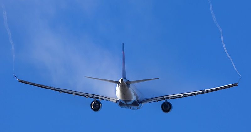
Winglets can be used to increase the effective aspect ratio of the wing without substantially increasing the wingspan. Winglets were designed by Richard Whitcomb at NASA Langley to help move the wingtip vortices away from the majority of the wing and reduce induced drag. Winglets do nothing to reduce the strength of the wing tip vortices, which depend on the wing’s lift (equal to weight). The effects are often apparent from the natural flow visualization, as shown in the photograph below, where it can be seen that the wing tip vortex is trailed from the very tip of the winglet, i.e., increasing the effective aspect ratio of the wing.
One approach to quantify this effect is to use an aspect ratio correction of the form
(49) 
where  is the “effective” or corrected aspect ratio,
  is the length or height of the winglet, as shown in the figure below, and
  , is a coefficient that depends on the winglet design.
  for a classic winglet. While winglets increase the wetted area, thereby increasing skin friction and overall profile drag, they still result in a net reduction in total aircraft drag.

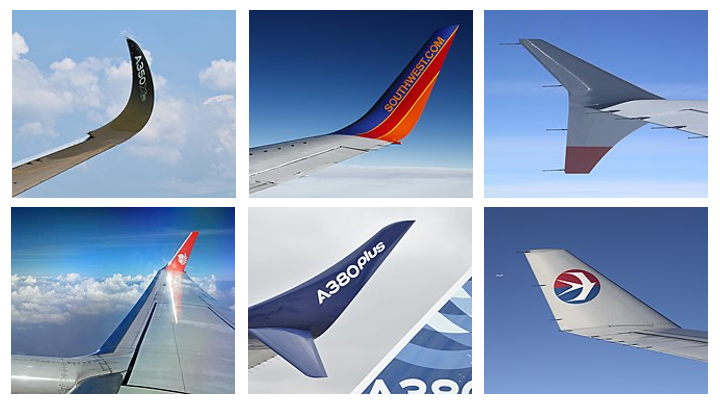
As shown in the images below, commercial airliners have employed various winglet designs. Today, the trend is toward using winglets with smooth chord variations in the wing-to-winglet region, which helps further minimize drag.
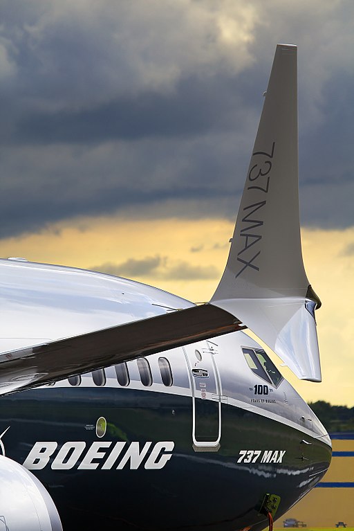
More recent variations of the winglet are featured on aircraft such as the Boeing 737 MAX, as illustrated in the photograph below, which is designed to reduce induced drag from the lifting wing further and enhance the aircraft’s flight efficiency and range. Increasing the length (height) of a traditional winglet from the wing’s top surface helps reduce induced drag, at least to a point, but it also increases the wing’s overall structural weight. Adding another winglet pointing downwards achieves the aerodynamic benefits without a significant weight penalty, perhaps a further 1%. While this may seem like a slight reduction in drag, the potential fuel savings are still significant over the aircraft’s operational life, which can benefit an airline by tens of millions of dollars per aircraft. It seems unlikely, however, that further reductions in induced drag can be realized by yet more permutations of the basic winglet design.
Summary & Closure
The geometrical parameters that define the shape of a wing include its span, chord distribution, aspect ratio, wash-out or another type of twist, and airfoil section shape. Wings may also have winglets, which help reduce overall wing drag. The overarching design requirement is to engineer the wing for good aerodynamic efficiency in terms of its lift-to-drag ratio at normal flight conditions and off-design conditions such as stall. The aerodynamics, however, also need to be balanced against the structural design of the wing in terms of its strength and stiffness, amongst other requirements such as flutter avoidance. Using winglets in increasingly innovative forms has led to significant drag reductions on wings, which can save substantial amounts of fuel, especially for airliners.
In airplane design, wing area and aspect ratio are essential in determining flight performance characteristics. The planform area, which represents the projected wing area, directly influences lift generation, affecting the airplane’s payload capacity, maneuverability, and efficiency at various airspeeds. The aspect ratio, which is the ratio of wingspan to chord, determines lift efficiency and drag, with higher aspect ratios resulting in lower drag for the airplane, leading to better fuel efficiency and higher cruising speeds. These parameters are tailored to the aircraft’s intended mission, with commercial airliners favoring higher wing aspect ratios for efficiency, fighter jets opting for lower ratios for high airspeed and flight agility, and sailplanes utilizing very high aspect ratio wings for superior soaring performance. Therefore, engineers must be able to calculate wing areas, aspect ratios, and mean chords, which are essential quantities used to characterize, design, and compare different aspects of aircraft performance.
5-Question Self-Assessment Quickquiz
For Further Thought or Discussion
- Do some research to determine what types of powered airplanes typically have the highest aspect ratio wings.
- Consider some non-engineering reasons why a large commercial airplane may have a limited wingspan.
- Why do sailplanes have extremely high aspect ratio wings? Explain carefully.
- Why do many fighter jet airplanes use sweptback wings with anhedral? Are there any commercial airliners that use wings with anhedral?
- Why might an airplane use a forward-swept wing rather than an aft-swept wing? Have any airplane been built with a forward-swept wing?
- Have any airplanes been successfully flown with different left and right wings?
- What might be the relative advantages of a conventional winglet versus a blended winglet?
Other Useful Online Resources
For more in-depth information on wings and wing shapes:
- Check out Shape Shifters from the Royal Aeronautical Society.
- See much more about different wing shapes!
- Boeing explains all about winglets!
- Other types of wings in-depth.
- Birds and their wing shapes.
- Usually with the addition of nose camber. ↵
- It is important not to confuse the wing area (capital "") with the semi-span of the wing (lowercase ""). ↵
- This officially sanctioned flight was the first successful aerial nonstop, non-refueled circumnavigation of the Earth. ↵
- The effort involved depends mainly on one's proficiency with geometry rather than aerodynamics. ↵
- The ability to reconcile different results for pitching moment coefficients often comes down to the realization that definitions and reference lengths can vary. ↵
