16 Mach Number & Reynolds Number
Introduction
The dimensionless (or non-dimensional) similarity parameters, Mach number and Reynolds number, have already been introduced. These parameters typically emerge from the process of dimensional analysis when applied to nearly all fluid flow problems. But what do they mean, how are their values interpreted, and how are they used?
Of all the various ways of categorizing different aerodynamic flows, the distinction based on the Mach number is one of the most useful; it can be used to help quantify the degree of compressibility effects in a flow. The Reynolds number is another useful aerodynamic parameter that helps quantify the relative impacts of inertia effects versus viscous effects in a flow. Hence, the classifications of flows and operating conditions based on the Reynolds number are also helpful. Mach and Reynolds numbers are so frequently encountered and used in aerodynamics that a broader understanding of their meaning and application becomes essential for engineers.
Learning Objectives
- Better appreciate the significance of Mach number in understanding compressibility effects on aerodynamic flows.
- Understand the significance of the Reynolds number in how it affects aerodynamic flows and other characteristics.
- Know how to calculate the Mach number and Reynolds number.
Definition of Mach Number
The Mach number is a quantity defined as the ratio of the local flow velocity to the local speed of sound in the same fluid at the same state, and is given by
(1) 
where  is the magnitude of the flow velocity (i.e., the flow speed or the true speed of a flight vehicle) and
  is the speed of sound. Usually, the magnitude sign is dropped by recognizing that both quantities are in units of speed, and so
(2) 
Remember that the Mach number is a dimensionless (and, therefore, unitless) parameter. It is just one of a series of dimensionless parameters encountered in engineering, known as similarity parameters. The Mach number is named after Ernst Mach, an Austrian physicist renowned for his contributions to various fields of physics, including the study of shock waves.
In general, the flow velocity  value can vary from point to point in a flow. The speed of sound may also differ from one point to another, especially in high-speed flows where compressibility effects are present and temperature changes occur. Therefore, the Mach number can also vary from point to point.
Using the principles of thermodynamics, at a constant temperature, the speed of sound in a gas is given by the square root of the ratio of the change in pressure to the change in density resulting from a disturbance, i.e.,
(3) 
For an ideal gas, the equation of state is  , where
  is the ratio of specific heats,
  is the gas constant (in appropriate engineering units), and
  is absolute temperature, so
(4) 
Therefore, the speed of sound is proportional to the square root of the absolute temperature, i.e.,
(5) 
Remember that using the correct values of and for the specific gas used, in the proper units, is essential for accurate numerical calculations of .
Significance of the Speed of Sound
A necessary consequence of the compressibility of a gas is that disturbances produced at one point propagate to another point at a finite speed, i.e., at the speed of sound . As an object (in this case, referred to as a point pressure or acoustic source) accelerates from rest, it emits disturbances in the form of spherical pressure waves, as shown in the figure below. The effect can be visualized by considering the points (open dots, right to left) as having generated a disturbance at previous times, the solid dot indicating the current time. The speed of sound is the same in all directions in a uniform, constant-temperature fluid, so these waves manifest in three-dimensional space as a series of offset concentric spheres.
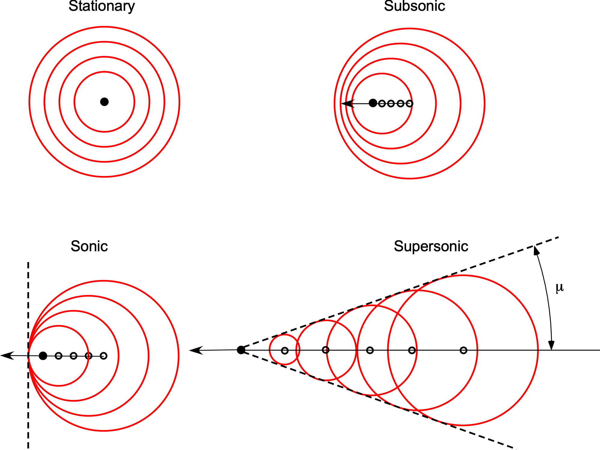
As the point source moves faster, the pressure waves appear to bunch closer together in the direction of motion and spread apart in the other direction, i.e., a Doppler effect. Eventually, as the source’s speed approaches the speed of sound, the source catches up with the previously produced pressure waves, which merge and form a wavefront perpendicular to the direction of travel, thereby creating the essence of a shock wave. The shock waves then bend back to form a Mach line for supersonic motion; although named after Ernst Mach, these oblique waves were first theorized by Christian Doppler.
The angle of the Mach wave,  , can easily be calculated because it will be apparent from the velocity components that
(6) 
where  is the velocity of the source,
  is the speed of sound, and
  is the Mach number of the source. Therefore, the Mach angle is simply
(7) 
Doppler effects near the speed of light?
As an object approaches the speed of light, it undergoes profound relativistic effects predicted by Einstein’s theory of special relativity. With his signature presentation style, Carl Sagan uses a Vespa scooter to explain what happens: “As your Vespa races toward the cosmic horizon, the colors around you shift—bluer, hotter, more energetic—until the very light itself transforms. Time slows, space contracts, and you become a streak of high-energy radiation, a ghostly blur in the eyes of the universe.” Time on the scooter slows down relative to an outside observer, while its length contracts in the direction of motion. Its mass effectively increases, requiring more and more energy to accelerate, making it impossible to reach the speed of light itself. Observers in front of the speeding Vespa would see it blue-shifted as the wavelengths of light it emits compress toward the shorter wavelength end of the spectrum, potentially shifting into ultraviolet or X-ray radiation at extreme speeds. Conversely, an observer behind it would see the scooter red-shifted as light waves stretch toward longer wavelengths. Carl Sagan might describe this cosmic Vespa ride as a journey where space warps, time distorts, and color transforms until the scooter becomes an ethereal streak of high-energy radiation, vanishing into the vastness of the universe. Of course, before reaching such speeds, your Vespa would likely be vaporized by sheer relativistic forces. But it’s fun to imagine!
Mach Number Regimes
It will now be apparent that in a compressible flow, there is an essential distinction between flows involving velocities less than the speed of sound (subsonic flow) and flows involving velocities greater than the speed of sound (supersonic flow). If  is the local Mach number at a point P in the flow, then by definition, the flow is locally:
- Subsonic if
 .
. - Sonic if
 .
. - Supersonic if
 .
.
The freestream Mach number is defined as the ratio of the freestream velocity (that is, the velocity far upstream of the airfoil) to that of the freestream sonic velocity, , i.e.,
(8) 
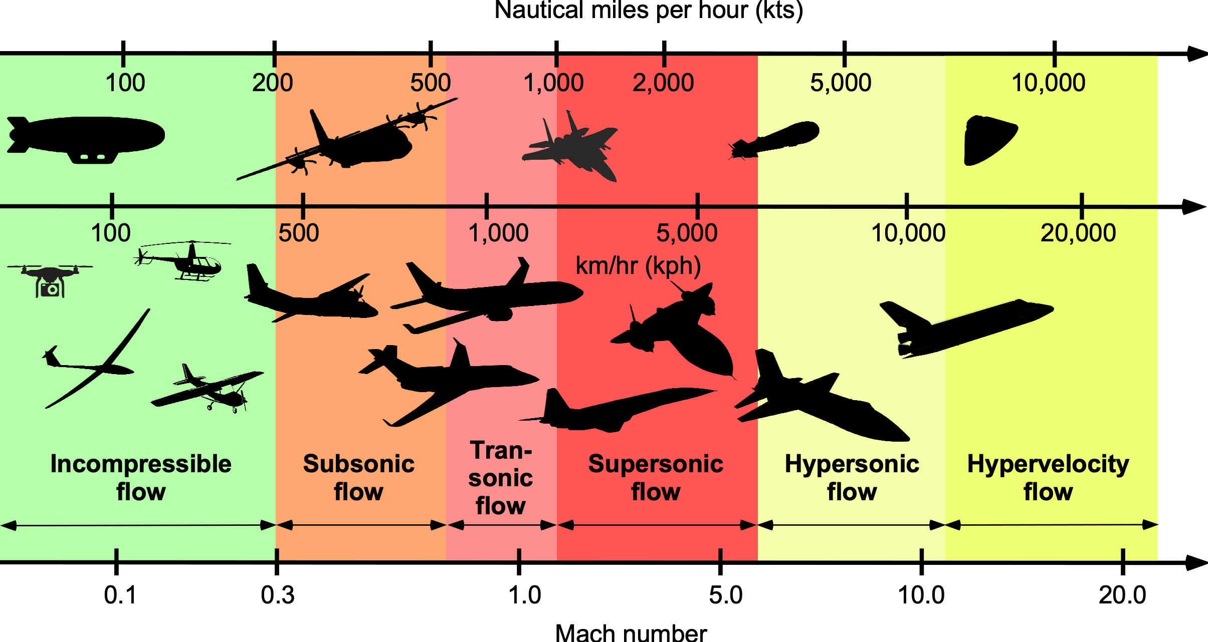
The figure below illustrates the categorization of flight vehicles based on their flight Mach number. The speed of sound at MSL ISA is about 1,117 ft/s (340 m/s, 768 mph, 1,236 km/h). Few air-breathing vehicles can sustain supersonic flight speeds of  .
.
Check Your Understanding #1 – Calculating the Mach number
An airplane is cruising at a true airspeed of 500 knots at 30,000 ft. Calculate the flight Mach number for these conditions. Assume ISA standard conditions.
Show solution/hide solution.
The airspeed is given as 500 knots, equivalent to 843.9 ft/s. The flight Mach number will be the airspeed divided by the speed of sound at this altitude. Using the International Standard Atmosphere (ISA) model, for which a handy online ISA calculator can be found here, the standard temperature at this altitude is -47.83 F or 411.84 R. According to the calculator, the corresponding speed of sound, a_{\infty, at this altitude and temperature, is 994.86 ft/s. This latter value can also be determined using
![\[ a_{\infty} = \sqrt {\gamma \, R \, T} = \sqrt{1.4 \times 1716.49 \times 411.84} = 994.86~\mbox{ft/s} \]](https://eaglepubs.erau.edu/app/uploads/quicklatex/quicklatex.com-57731e490b5fed882d2c02c69e52c985_l3.svg "Rendered by QuickLaTeX.com")
where the gas constant for air is 1716.49 ft lb slug R. Therefore, the flight Mach number is
![\[ M_{\infty} = \frac{V_{\infty}}{a_{\infty}} = \frac{843.9}{994.85} = 0.84 \]](https://eaglepubs.erau.edu/app/uploads/quicklatex/quicklatex.com-63fa62d005026e72e588a6df4f140506_l3.svg "Rendered by QuickLaTeX.com")
Physical Interpretation of Mach Number
In terms of a physical interpretation, the Mach number can also be expressed as
(9) 
The elastic effects can be expressed in terms of the bulk modulus of elasticity,  , also called the volume modulus. The bulk modulus is a material property that characterizes the compressibility of a fluid, i.e., the ability of an applied pressure to change the fluid’s volume and density. An increase in pressure will decrease the volume, leading to an increase in density.
In terms of the bulk modulus, the speed of sound is given by
(10) 
An increase in bulk modulus indicates an increasingly incompressible fluid, i.e., the speed of sound increases.
Using the result in Eq. 10, gives
(11) 
Therefore, the Mach number can also be expressed as
(12) 
where  is a characteristic length scale. On the numerator, the grouping
  represents an inertial force in the flow. The term
  on the denominator represents an elastic force. The Mach number, therefore, represents a relative measure of inertial to elastic forces in a flow, i.e., a measure of the compressibility of the flow medium.
Compressible Flows about an Airfoil
Below a Mach number of about 0.3, the air or other gas can be considered incompressible. However, if the freestream Mach number becomes sufficiently high (usually  ), then the flow may locally exceed the speed of sound as it moves over a wing or other parts of a flight vehicle, i.e., . This situation gives rise to a mixed subsonic/supersonic flow field, known as transonic flow, as shown in the figure below. Most jet transport aircraft fly in transonic conditions where the freestream Mach number is subsonic, but the local Mach numbers at some points on the wings are supersonic. Today, these aircraft utilize supercritical wing sections, enabling them to fly efficiently at airspeeds approaching the speed of sound.
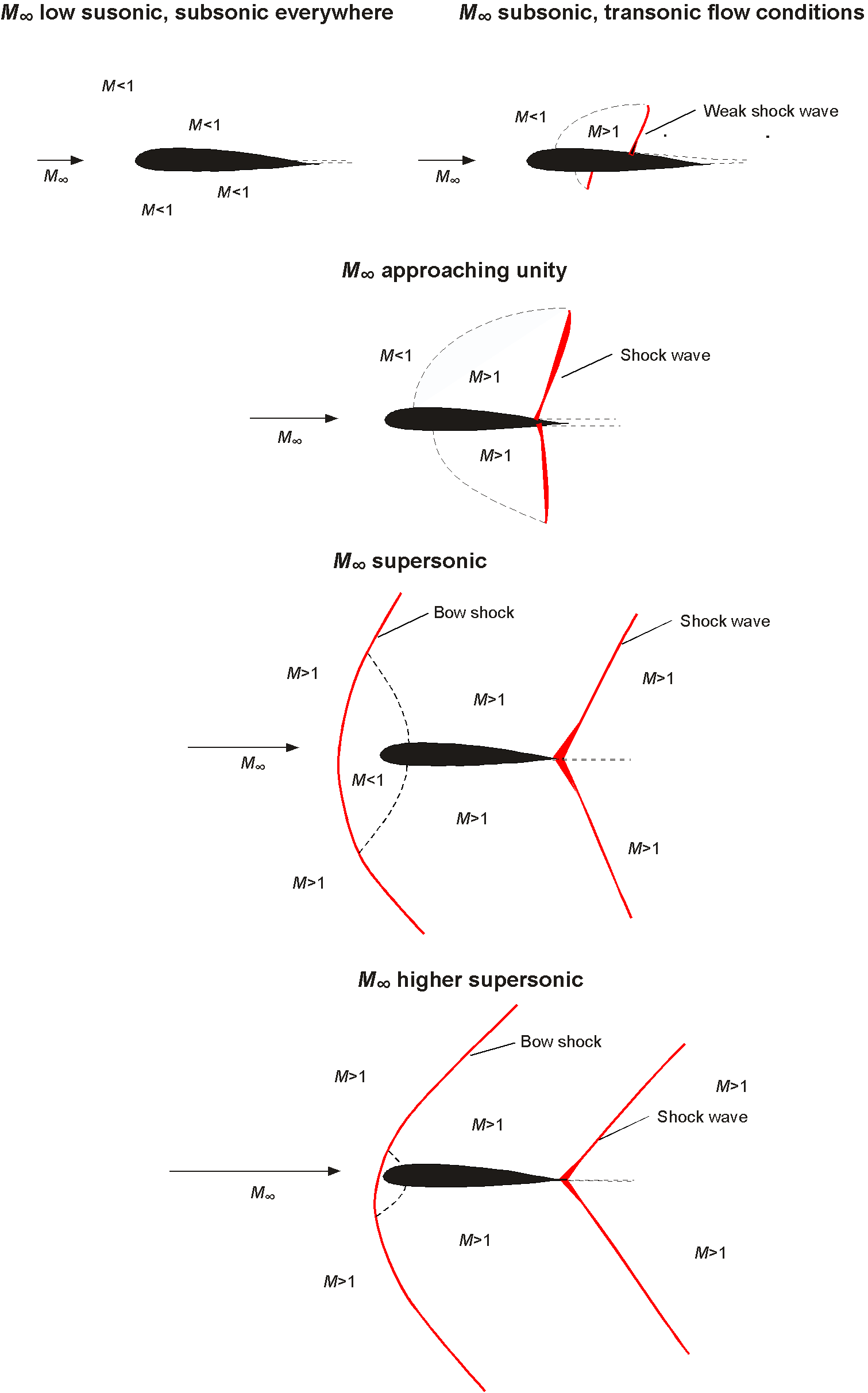
Shock waves occur in fully supersonic flows, where the Mach number, , exceeds unity everywhere. They involve an abrupt flow change in pressure, density, and temperature, as well as an irreversible process caused by viscosity and thermal conduction effects inside the shock wave. Therefore, the formation of shock waves leads to losses of pressure, momentum, and energy, manifesting as a source of drag on a flight vehicle known as wave drag.
At hypersonic speeds, which are usually defined for  , not only do strong shock waves form, but kinetic heating and chemical dissociation of the air can also occur. However, hypersonic flows still require further understanding and are the subject of ongoing research.
Supersonic Flow Around an Aircraft
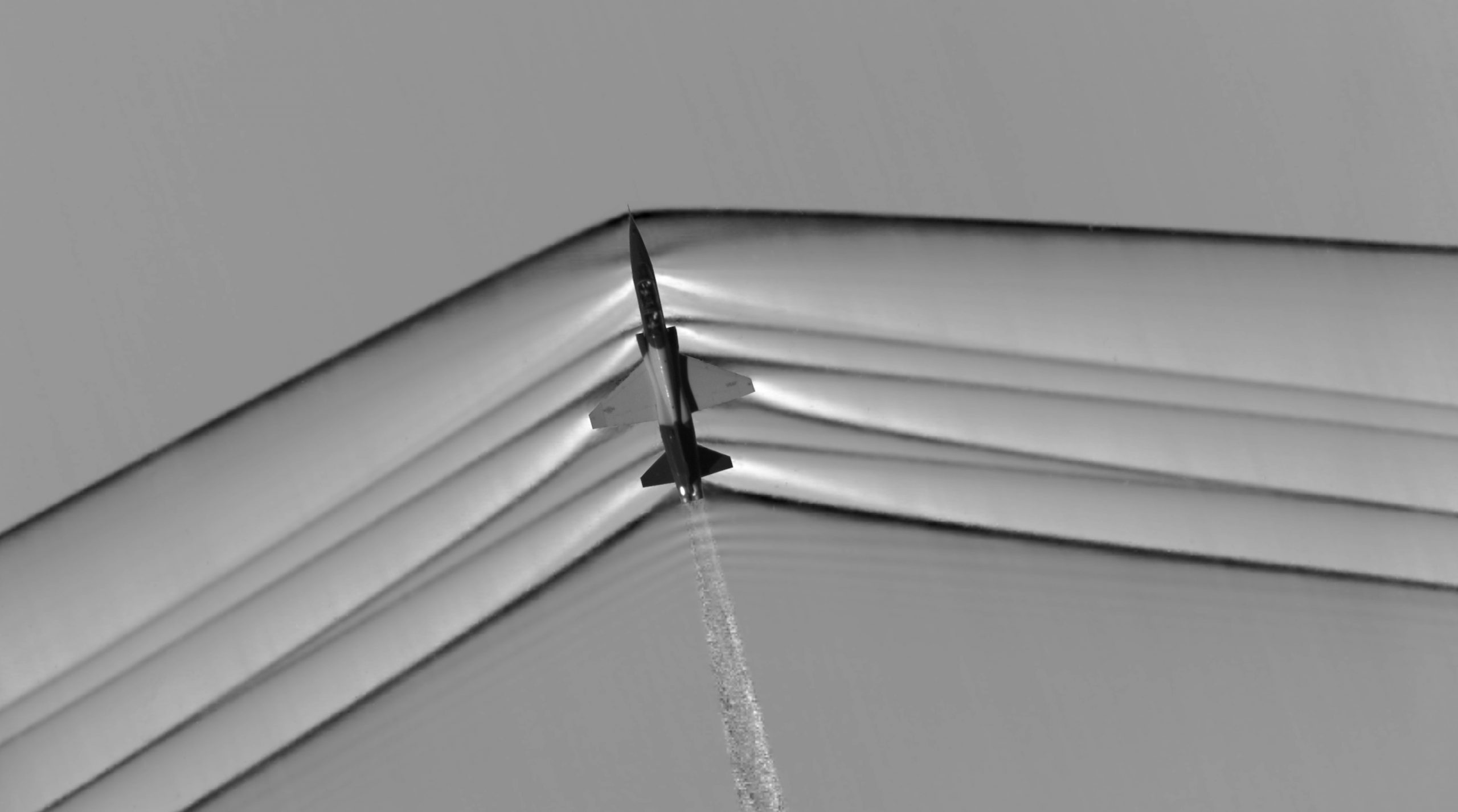
The photo below shows a fascinating schlieren image of the multitude of Mach (shock) waves an aircraft generates during supersonic flight, with the Mach cones clearly visible. Notice the powerful shock waves (Mach cone) produced at the nose and tail of the aircraft, which are responsible for the sonic booms heard on the ground. The flight Mach number is easily determined from the Mach angle, which, in this case, is about 70 degrees because
(13) 
then
(14) 
so the aircraft is just flying supersonically. Notice also the turbulence and sound waves in the wake of the aircraft from the engine and its hot exhaust, the latter of which appears as a shimmering effect because of the turbulence.
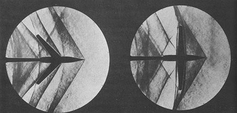
The images below are schlieren flow visualization about a model of a fighter airplane in a supersonic wind tunnel. Notice that schlieren images are inevitably circular because the technique uses parabolic mirrors. Notice the build-up in the number and intensity of the almost normal shock waves as Mach 1 is approached. In supersonic flight, the Mach cone becomes increasingly swept back as the flight Mach number increases. The angle is used to denote the Mach angle, as given by
(15) 
which is the half-apex angle of the Mach cone.

Therefore, the Mach angle is 90 at
at  , and its value decreases quickly beyond Mach 1, as shown in the figure below. Notice that even by a Mach number of 2, the Mach cone is already swept back 60 to a half apex angle of
  . For hypersonic speeds, the Mach angle is so steep that it can touch the body’s surface, so a blunt or bluff body shape is often a better design solution to keep the shock waves away from the surface.
What is a schlieren flow visualization system?
Schlieren is an optical technique to visualize variations in a fluid’s refractive index. It can help study the flow patterns in gases or liquids. The word “schlieren” is derived from the German word for “streaks” or “striae.” In a schlieren system, a point light source emits light into the region of the fluid flow. The flow must have variations in density.
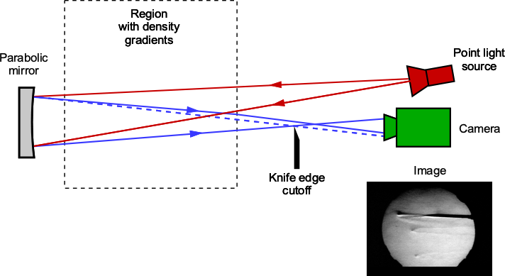
These so-called “density gradients” cause slight changes in the fluid’s refractive index, which in turn bend or “refract” the light passing through it. A knife edge, such as a razor blade, is placed in the light path after interacting with the fluid flow, which “cuts off” part of the refracted light. An imaging system, such as a camera, then captures the remaining light. Higher- or lower-density regions appear as light and dark areas or streaks, providing insights into phenomena such as shockwaves, boundary layers, turbulence, and other flow characteristics.
Why Wing Sweep is Important
The Mach angle is essential in supersonic wing design because pressure disturbances in a supersonic flow are confined to the cone region as determined by the Mach angle. Unlike a subsonic flow, there is no upstream influence beyond the Mach cone in a supersonic flow; pressure disturbances are only transmitted along the Mach cone and downstream. The consequence is profound because if the wing’s leading edge is swept back behind the Mach cone, the wing experiences relatively lower drag (i.e., low wave drag), as shown in the schlieren images below. Otherwise, if the shock wave reaches the wing, the effects of the shock will cause disruptions to the flow in the boundary layer, increasing drag and potentially leading to flow separation.
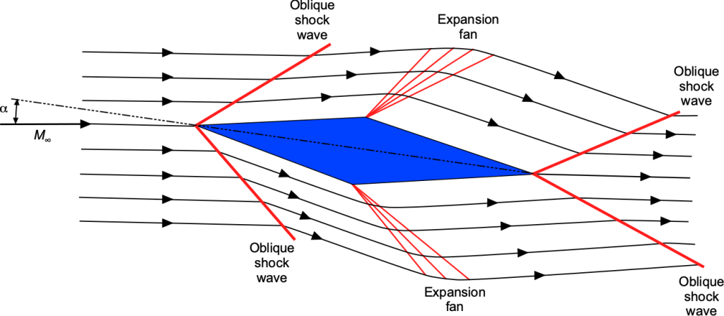
Supersonic Airfoils
Unlike subsonic airfoils, supersonic airfoils produce shock waves, which affect the airflow and aerodynamic performance of the airfoil. Oblique compression shock waves occur at the leading and trailing edges of the airfoil. At the points of maximum thickness, expansion waves form, causing the Mach number to increase and the pressure to decrease after the expansion is complete. Rarefaction shock waves form at the trailing edge, increasing the Mach number and returning the pressure to the freestream value. The higher pressure on the lower front half of the airfoil and the upper rear half generates the lift.
Definition of Reynolds Number
The Reynolds number is another important parameter used in categorizing aerodynamic flows. Osborne Reynolds conducted fundamental experiments to understand fluid dynamics better and developed a statistical, mathematical framework for studying turbulence. The Reynolds number is given the symbol  and is defined as
(16) 
where  and are the fluid’s density and viscosity, respectively, is a reference velocity, and is a characteristic length. Notice that when quoting the value of the Reynolds number, the characteristic length must be defined, e.g., the Reynolds number based on chord length, diameter, etc.
The Reynolds number is also a dimensionless parameter, and it is another similarity parameter used in aerodynamics. The Reynolds number is essential in understanding aerodynamics because it governs the relative magnitude of inertia effects to viscous effects in the flow. Hence, the Reynolds number affects the drag and aerodynamic efficiency of a flight vehicle.
The reference velocity is often the freestream velocity , and the density is the freestream density  . For a wing, the reference length is the wing chord
  (
( ), so the Reynolds number based on the chord is
(17) 
This latter form of the Reynolds number, which people first encounter in their study of aerodynamics, is one of many forms encountered in practice. This form is often used to scale flow situations, such as between an aircraft model in a wind tunnel and one in flight, to obtain the full-size dynamic flow similarity.
When the values of air density and viscosity are substituted into the equation for the Reynolds number for representative flight vehicles and flight speeds, the values of the Reynolds number will vary over many orders of magnitude and are often expressed in terms of “millions.”
Check Your Understanding #2 – Calculating the Reynolds number
The wing of an airplane has a mean aerodynamic chord  = 2.75 m, and it is in cruise flight at a freestream Mach number of 0.82 at an altitude of 30,000 ft. Calculate the Reynolds number for these conditions. Assume ISA standard conditions.
Show solution/hide solution.
The Reynolds number will be
![\[ Re_c = \frac{\varrho_{\infty} V_{\infty} \overline{c}}{\mu_{\infty}} = \frac{0.45904 \times 248.65 \times 2.75}{1.4876\times 10^{-5} } = 2.11 \times 10^7 \]](https://eaglepubs.erau.edu/app/uploads/quicklatex/quicklatex.com-315c7d8465f9395feef2fb45a6608532_l3.svg "Rendered by QuickLaTeX.com")
So, the Reynolds number is about 27 million. Again, the atmospheric properties have been evaluated using the International Standard Atmosphere (ISA) model, for which a handy online ISA calculator can be found here.
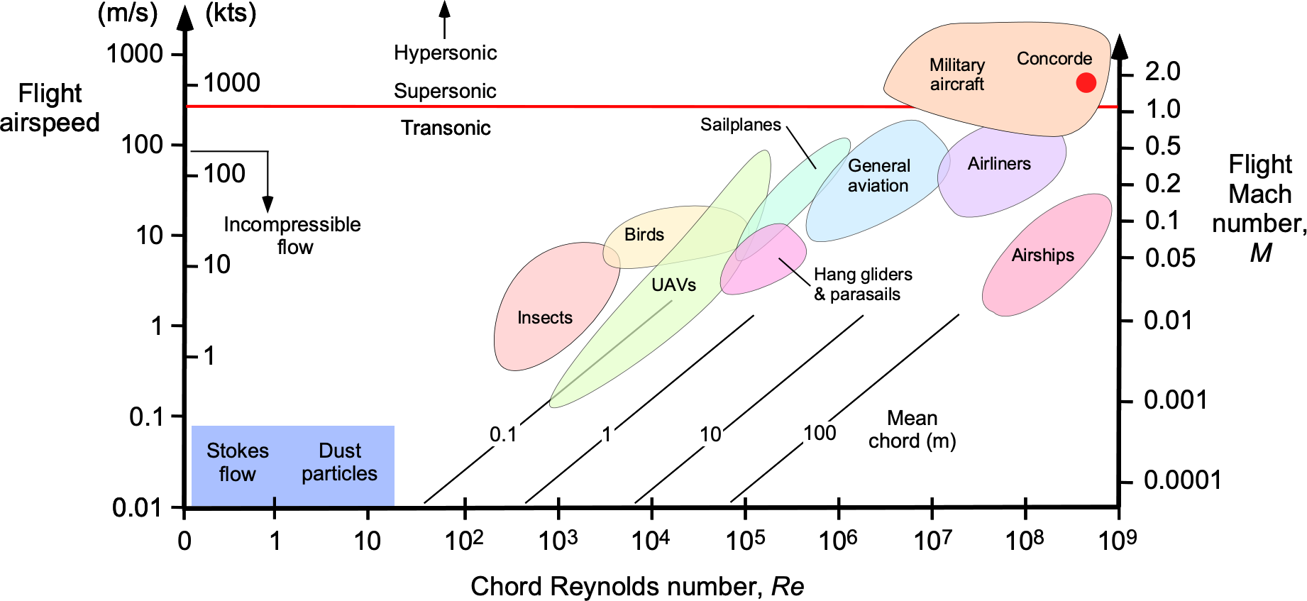
The figure below summarizes the range of Mach and Reynolds numbers (based on the chord) for various flight vehicles and other things. Notice the logarithmic scales. Tiny flying creatures, such as birds and insects, encounter such low Reynolds numbers during flight that most of their energy is spent overcoming the effects of viscosity. The Reynolds numbers for jet airplanes range from 10 to 10
to 10 , i.e., from 10 to 100 million. Model aircraft (and many UAVs) will have Reynolds numbers much smaller in the 10
 to 10
to 10 range.
It will also be apparent that the Reynolds and Mach numbers are interrelated by the velocity, . For example, the Reynolds number based on chord can be written in terms of the freestream Mach number as
(18) 
Using the values for , and  for air at standard sea-level conditions then
(19) 
or in SI units
(20) 
This interdependence of  and poses an interesting dilemma in the investigation of Reynolds number and Mach number on items being tested in a conventional wind tunnel because and cannot easily be varied separately. Nevertheless, in a practical sense, the effects of the Reynolds number are more important at low Mach numbers, and at higher Mach numbers, the Reynolds number has somewhat less importance.
Physical Interpretation of Reynolds Number
It has been mentioned that the Reynolds number is important in aerodynamics because it governs the relative magnitude of viscous effects to inertia effects in the flow. This fact can be seen by writing the Reynolds number as
(21) 
On the numerator, the grouping  has units of force (pressure times an area), so in this case, it represents an inertial force, i.e., after the flow is moving, it has the propensity to keep moving. The coefficient of viscosity, , is the shear force per unit area per unit velocity gradient, so the ratio
  has dimensions of a velocity gradient, which is expected based on Newton’s law of viscosity. Therefore, the grouping on the denominator represents a viscous force, which acts to retard or slow its motion. The Reynolds number, therefore, represents a relative measure of inertial to viscous effects in a flow.
This outcome, as it explains the effects of the Reynolds number, is significant in aerodynamics. For example, the results in the figure below show the lift-to-drag ratio of several airfoil sections as a function of the Reynolds number based on chord length, i.e.,
(22) 
where is the chord or distance from the leading edge to the wing’s trailing edge. The lift-to-drag ratio, i.e., the ratio of lift to drag, is a measure of aerodynamic efficiency; therefore, these results reveal a significant effect of varying the Reynolds number.
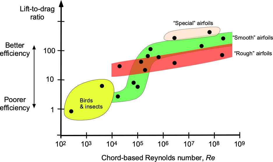
The operation of the airfoil (or wing) at higher chord Reynolds numbers, e.g., higher flow speeds, will improve aerodynamic efficiency because the inertial effects dominate over the viscous effects. Notice that the Reynolds number can also be increased by increasing the scale (size) of the wing. However, at lower Reynolds numbers, the relative effects of viscosity are higher, which manifests as higher profile drag and a lower lift-to-drag ratio.
The underlying physics behind these preceding effects on airfoil efficiency is tied to the developing boundary layers on the airfoil’s surface. Boundary layers are small regions immediately adjacent to the surface where viscous flow effects are significant. The boundary layers are relatively thin at higher Reynolds numbers, resulting in reduced profile drag. However, they are thicker at lower Reynolds numbers, increasing profile drag.
 A boundary layer as it develops over the surface of an airfoil.
It is now apparent that the Reynolds number is a fundamentally important parameter in studying boundary layers and other viscous effects. The developing nature of the boundary layer can be characterized by a local Reynolds number. Instead of the Reynolds number being based on chord length, the length can be measured in terms of the distance  from the point where the flow initially develops, i.e.,
(23) 
For example, in the case of an airfoil, is measured from the stagnation point at the nose to the downstream distance .
Experiments have shown that at Reynolds numbers based on  above about
  , the boundary layer becomes turbulent, which increases skin friction drag. The reason for this behavior is that natural flow disturbances develop, even over perfectly smooth surfaces, and cause a transition from a laminar to a turbulent boundary layer. Numerous experiments have investigated the transition from laminar to turbulent flow. In all cases, the transition correlates to a specific value (or a small range) of the Reynolds number, based on the downstream distance. Because turbulent mixing occurs progressively, the transition from a fully laminar boundary layer flow to one that is fully turbulent is a process that occurs over a certain distance, i.e., it is a gradual process rather than a sudden event.
Summary & Closure
The Mach number is defined as the ratio of the fluid velocity to the speed of sound in the fluid, while the Reynolds number is defined as the ratio of inertial forces to viscous forces. The Mach number is a measure of compressibility effects. The Mach number also determines whether a flow is subsonic, transonic, or supersonic. The Reynolds number helps determine whether the flow is laminar or turbulent, and is also a measure of the significance of inertial effects to viscous effects in a flow. Understanding the importance of these two parameters is crucial for comprehending aerodynamic flows and accurately predicting flow behavior under various conditions. Both parameters are used routinely in aerodynamic problem-solving for flow around airfoils, wings, and complete aircraft, so their fundamental significance must be appreciated and understood.
5-Question Self-Assessment Quickquiz
For Further Thought or Discussion
- Calculate the Mach number and Reynolds number of the wing of a Cessna 172 in cruise flight at 5,000 ft (or use 1,800 m). Hint: Use the standard properties of the atmosphere.
- Do some research to determine the likely range of Mach and Reynolds numbers a rocket will encounter as it leaves the Earth’s atmosphere.
- The speed of sound in helium is nearly three times that of air. Explain why and what some interesting consequences might be.
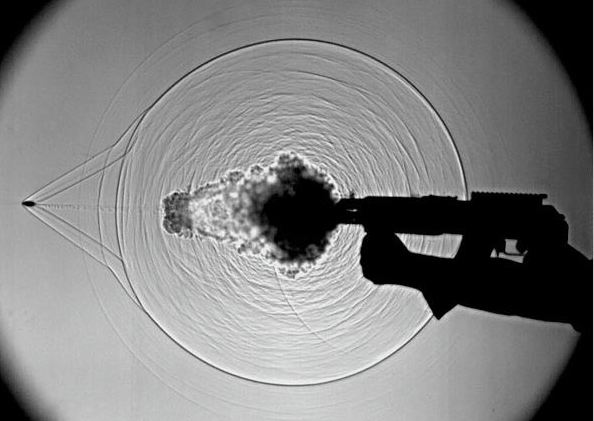
- Study the image below, which is a schlieren flow visualization of what is produced when a bullet is fired from a gun. What is the bullet’s approximate flight Mach number? Can you explain the origin of the other (circular) waves?
Additional Online Resources
To improve your understanding of the use of similarity parameters in engineering, navigate to some of these online resources:
- Airplanes approaching the sound barrier – another film by Shell Oil.
- High-speed flight: Part 1, and Parts 2 & 3.
- A movie of wind tunnel testing of Concorde.
- Supersonic flight and sonic booms – what they sound like!
- Top 5 sonic booms caught on camera!
- Video on Reynolds number.
- Video: Reynolds’ experiment.
- Video: Physics of Life – The Reynolds Number and Flow Around Objects
- Smarter Every Day: Shockwaves generated by bullets.
