74 Worked Examples: Internal Flows
These worked examples have been fielded as homework problems or exam questions.
Worked Example #1
Oil with a density  kg m
kg m and kinematic viscosity
  =
= m
m s
s , flows at 0.2 m
 s through a 500 m length of 300 mm diameter cast iron pipe. The average roughness of the pipe’s surface is
  = 0.26 mm. Calculate: (a) The average flow velocity in the pipe. (b) The Reynolds number of the flow and explain if the flow is laminar or turbulent. (c) The pressure drop and head loss along the pipe. (d) The minimum power required by the pump to move the oil.
(a) The average flow velocity is calculated from the volume flow rate, i.e.,
![\[ V_{\rm av} = \frac{Q}{A} \]](https://eaglepubs.erau.edu/app/uploads/quicklatex/quicklatex.com-1d275cdd8801e737bf3f534e7a8a5e05_l3.svg "Rendered by QuickLaTeX.com")
so the average flow velocity is given by
![\[ V_{\rm av} = \frac{4Q}{\pi d^2} = \frac{4 \times 0.2}{\pi \times 0.3^2} = 2.83~\mbox{m s$^{-1}$} \]](https://eaglepubs.erau.edu/app/uploads/quicklatex/quicklatex.com-663629b2d02b149f21ac3dcc2eecbfc8_l3.svg "Rendered by QuickLaTeX.com")
(b) The Reynolds number of the flow in the pipe is
![\[ Re_d = \frac{\varrho_{\rm oil} \, V_{\rm av} \, d}{\mu_{\rm oil} } =\frac{V_{\rm av} \, d}{\nu_{\rm oil}} = \frac{2.83\times 0.3 }{10^{-5}} = 84,900 \]](https://eaglepubs.erau.edu/app/uploads/quicklatex/quicklatex.com-bd760e42666ce3d957e5362ee5411bd5_l3.svg "Rendered by QuickLaTeX.com")
So the pipe flow will be turbulent because the Reynolds number is greater than 2,000, and we will need to use the Moody chart to find the friction factor  .
.
(c) We now need the pressure drop and head loss along the pipe. To use the Moody chart, we also need the relative surface roughness, which is
![\[ \frac{\epsilon}{d} = \frac{0.26}{300} = 0.00087 \]](https://eaglepubs.erau.edu/app/uploads/quicklatex/quicklatex.com-1168dcb9d2921ab9f16506366bb770c8_l3.svg "Rendered by QuickLaTeX.com")
From the Moody chart for a Reynolds number of 84,900 and a relative roughness of 0.00087 (using interpolation), we have 
 . Therefore, the pressure loss over the length of the pipe is
![\[ \Delta p = \frac{1}{2} \varrho_{\rm oil} V_{\rm av}^2 f \left( \frac{L}{d}\right) \]](https://eaglepubs.erau.edu/app/uploads/quicklatex/quicklatex.com-93f29c5700a25dba2e8883742373bbb7_l3.svg "Rendered by QuickLaTeX.com")
and inserting the values gives
![\[ \Delta p = 0.5\times 900.0\times 2.83^2 \times 0.022\times \left( \frac{500.0}{0.3}\right) = 132.15~\mbox{kPa} \]](https://eaglepubs.erau.edu/app/uploads/quicklatex/quicklatex.com-1450a2be4a3168a46b6612b3cecb2b98_l3.svg "Rendered by QuickLaTeX.com")
The corresponding head loss over this pipe is
![\[ h = \frac{\Delta p}{\varrho_{\rm oil} \, g} = \frac{132.15\times 10^3}{900\times 9.81} = 14.97~\mbox{m} \]](https://eaglepubs.erau.edu/app/uploads/quicklatex/quicklatex.com-55435b1b83a3a29f0d70e819d3299e80_l3.svg "Rendered by QuickLaTeX.com")
(d) The pumping power required will be
![\[ P_{\rm req} = Q \, \Delta p_{AB} = 0.2 \times 132.15 \times 10^3 = 26.43~\mbox{kW} \]](https://eaglepubs.erau.edu/app/uploads/quicklatex/quicklatex.com-efab1ff353403012a0f1ce63263d6860_l3.svg "Rendered by QuickLaTeX.com")
Worked Example #2
You are tasked with designing the fuel delivery system. The system requires a flow through a smooth pipe of 200 m in length and 15 mm in diameter. The required fuel flow rate is 125 kg hr. The fluid properties of the fuel are given as:  800 kg m and
  0.00164 kg m s. All entrance effects can be disregarded. (a) What is the pressure drop along the length of the pipe? (b) What pressure capability (in terms of head) is required of the pump? (c) What are the pumping power requirements?
(a) The cross-sectional area of the pipe is
![\[ A_c = \frac{\pi D^2}{4} = \frac{\pi \times 0.015^2}{4} = 0.0001767~\mbox{m${^{2}}$} \]](https://eaglepubs.erau.edu/app/uploads/quicklatex/quicklatex.com-602cd4c992e311f53089542ba67f1012_l3.svg "Rendered by QuickLaTeX.com")
The mass flow rate  is given as 125 kg hr = 0.0347~kg s, i.e.,
![\[ \overbigdot{m} = \varrho \, A_c V_{\rm av} = 0.0347~\mbox{kg s$^{-1}$} \]](https://eaglepubs.erau.edu/app/uploads/quicklatex/quicklatex.com-f70b73fdaf7f196db4dd6b7587eac7c6_l3.svg "Rendered by QuickLaTeX.com")
So, the average flow velocity in the pipe is
![\[ V_{\rm av} = \frac{\overbigdot{m}}{\varrho \, A_c} = \frac{0.0347}{800.0 \times 0.0001767} = 0.246~\mbox{m s$^{-1}$} \]](https://eaglepubs.erau.edu/app/uploads/quicklatex/quicklatex.com-64bc6342b4b77f9868aa2cc785e1b6a9_l3.svg "Rendered by QuickLaTeX.com")
The Reynolds number based on pipe diameter is
![\[ Re = \frac{\varrho V_d \, D}{\mu} = \frac{ 800.0 \times 0.246 \times 0.015}{0.00164} = 1,797 \]](https://eaglepubs.erau.edu/app/uploads/quicklatex/quicklatex.com-5560ca885dad35d6ee81ee58897a9f51_l3.svg "Rendered by QuickLaTeX.com")
Notice that this Reynolds number is in the laminar regime, so the friction factor is given by
![\[ f = \frac{64}{Re} = \frac{64}{1,797} = 0.0356 \]](https://eaglepubs.erau.edu/app/uploads/quicklatex/quicklatex.com-860f5af871072ec6f2f3ae5281911d66_l3.svg "Rendered by QuickLaTeX.com")
The pressure drop  is given by
![\[ \Delta p = \frac{1}{2} \varrho V_{\rm av}^2 \, f \left( \frac{L}{d}\right) \]](https://eaglepubs.erau.edu/app/uploads/quicklatex/quicklatex.com-a30a1663e26018c4cbaf88f9774c1109_l3.svg "Rendered by QuickLaTeX.com")
and inserting the values gives
![\[ \Delta p = \frac{1}{2} \times 800.0 \times 0.246^2 \times 0.0356 \times \left( \frac{200.0}{0.015} \right) = 11,457.4~\mbox{Pa} = 11.46~\mbox{kPa} \]](https://eaglepubs.erau.edu/app/uploads/quicklatex/quicklatex.com-5a4ae941d986c227182ef631061dff61_l3.svg "Rendered by QuickLaTeX.com")
(b) The equivalent head loss  will be
![\[ h = \frac{\Delta p}{\varrho \, g} = \frac{11,457.4}{800.0 \times 9.81} = 1.46~\mbox{m} \]](https://eaglepubs.erau.edu/app/uploads/quicklatex/quicklatex.com-b4010622f9bc0acbb596d7e059b2009f_l3.svg "Rendered by QuickLaTeX.com")
(c) The pumping power  can be determined from
![\[ P = \frac{\overbigdot{m} \, \Delta p}{\varrho} = \frac{0.0347 \times 11,457.4}{800.0} = 0.497~\mbox{W} \]](https://eaglepubs.erau.edu/app/uploads/quicklatex/quicklatex.com-f6fd834c56d3b8e4917fb631fa9ea83c_l3.svg "Rendered by QuickLaTeX.com")
Worked Example #3
Oil at 20  C, with density
  = 888.0 kg m and viscosity
  = 0.800 kg m s, respectively, is flowing steadily through a 6 cm diameter pipe that is 40 m long. The pressure at the inlet and outlet of the pipe is 745 kPa and 97 kPa, respectively. Determine the flow rate of oil through the pipe.
This pressure drop is a direct consequence of the action of viscous effects. The fluid is oil (dense and thick), so we expect the flow to be at a very low Reynolds number (i.e., laminar). One of the first goals in pipe flow problems is to determine the Reynolds number to verify the laminar assumption or to demonstrate that it is turbulent ( > 2,000). Based on the information provided in this problem, the only unknown is
  . From laminar pipe flow theory, we have that
![\[ \Delta p = p_1 - p_2 = \frac{8 \mu \, L \, V_{\rm av}}{R^2} = \frac{32 \, \mu \, L \, V_{\rm av}}{D^2} \label{lam} \]](https://eaglepubs.erau.edu/app/uploads/quicklatex/quicklatex.com-473f5da4c78de3c0e3d7885b79711535_l3.svg "Rendered by QuickLaTeX.com")
Notice that for a given length of pipe, the pressure drop is proportional to the fluid’s viscosity and flow speed (so the faster we try to move a given fluid, the larger the pressure drop will be) but inversely proportional to the square of the pipe diameter. The average flow velocity is
![\[ V_{\rm av} = \frac{\left( p_1 - p_2 \right) D^2}{32 \, \mu \, L} = \frac{\left(745.0 - 97.0 \right) \times10^3 \times (0.06)^2}{32 \times 0.8 \times 40} = 2.28~\mbox{m s$^{-1}$} \]](https://eaglepubs.erau.edu/app/uploads/quicklatex/quicklatex.com-e71b226b3babbbb334a6a5d132346bcf_l3.svg "Rendered by QuickLaTeX.com")
We can now check to see that the flow is laminar by calculating the pipe Reynolds number, i.e.,
![\[ Re = \frac{\varrho V_{\rm av} \, D}{\mu} = \frac{888.0 \times 2.28 \times 0.06}{0.80} = 151.8 \]](https://eaglepubs.erau.edu/app/uploads/quicklatex/quicklatex.com-0aff8b48391890847d1d5038dedf45dd_l3.svg "Rendered by QuickLaTeX.com")
So it is very low, much less than 2,000, and the expectation of laminar flow is verified, confirming the correct equation (Eq. ??) for the pressure drop. The volume flow rate through the pipe will be
![\[ Q = A \, V_{\rm av} = \frac{\pi D^2}{4} V_{\rm av} = \frac{\pi \left( p_1 - p_2 \right) D^4}{128 \, \mu \, L} \]](https://eaglepubs.erau.edu/app/uploads/quicklatex/quicklatex.com-ad06ad8fd0a199c32d64ec8f58c72e20_l3.svg "Rendered by QuickLaTeX.com")
Substituting in the known values gives
![\[ Q = \frac{\pi \left( p_1 - p_2 \right) D^4}{128 \, \mu \, L} = \frac{\pi \left(745.0 - 97.0 \right) \times10^3 \times (0.06)^4}{128 \times 0.8 \times 40.0} = 0.00644~\mbox{m${^3}$ s$^{-1}$} \]](https://eaglepubs.erau.edu/app/uploads/quicklatex/quicklatex.com-0ea7ca28784513d48aa41bfeba43ff5e_l3.svg "Rendered by QuickLaTeX.com")
The corresponding mass flow rate of oil will be
![\[ \overbigdot{m} = \varrho \, Q = 888.0 \times 0.00644 = 5.72~\mbox{kg s$^{-1}$} \]](https://eaglepubs.erau.edu/app/uploads/quicklatex/quicklatex.com-b7ab43d536a4aeab6e6327359caffbf0_l3.svg "Rendered by QuickLaTeX.com")
Worked Example #4
A coolant-type fluid used in the air-conditioning system of an aircraft is flowing through a smooth, 0.12-inch-diameter, 30-ft-long horizontal pipe steadily at an average flow speed of 3 ft/s . The fluid has a temperature of 40F, = 1.93 slug ft, and = 3.326
 10
10 slug fts. Determine for this pipe flow: (a) The Reynolds number of the flow based on the pipe diameter and whether the flow is laminar or turbulent; (b) The pressure drop along the length of the pipe; (c) The pumping power required to overcome this pressure drop; (d) Because the pump manufacturer provides pumps measured in pressure units of “head of inches of water,” what is the minimum head needed?
The pressure losses associated with the pipe flow are determined using the equation
![\[ \Delta p_L = \frac{1}{2}\varrho V_{\rm av}^2 \, f \left( \frac{L}{D} \right) \]](https://eaglepubs.erau.edu/app/uploads/quicklatex/quicklatex.com-96fc37170e972bd072c80d41c581de6c_l3.svg "Rendered by QuickLaTeX.com")
where is the Darcy-Welsbach friction factor. The friction factor depends on the flow Reynolds number and the roughness of the pipe material. Hence, the pressure loss in a pipe is also a function of the Reynolds number and the pipe’s roughness. Remember that the frictional effects of viscosity cause this pressure loss, which is irrecoverable and subsequently appears as heat.
(a) The Reynolds number of the flow can be calculated using the equation
![\[ Re = \frac{\varrho_{} V_{\rm av} \, D}{\mu_{}} = \frac{1.93 \times 3.0 \times 0.12/12}{3.326 \times 10^{-5}} = 1,740 < 2,300, \mbox{i.e., laminar Flow} \]](https://eaglepubs.erau.edu/app/uploads/quicklatex/quicklatex.com-9e081604b020b9f10e6055fa0ea1687c_l3.svg "Rendered by QuickLaTeX.com")
(b) The pressure loss can be determined using the equation
where the friction factor for the laminar flow in a smooth pipe is
![\[ f = \frac{64}{Re} \]](https://eaglepubs.erau.edu/app/uploads/quicklatex/quicklatex.com-dee33d9b42ed1613425c6655408dec87_l3.svg "Rendered by QuickLaTeX.com")
Therefore
![\[ \Delta p_L = \frac{1}{2}\varrho V_{\rm av}^2 \frac{64}{Re} \left( \frac{L}{D} \right) = 32\varrho V_{\rm av}^2 \left( \frac{L}{D} \right) \frac{\mu}{\varrho V_{\rm av}D} = \frac{32\mu V_{\rm av} L}{D^2} \]](https://eaglepubs.erau.edu/app/uploads/quicklatex/quicklatex.com-3e71f31049bd5829ddd5b0667712605b_l3.svg "Rendered by QuickLaTeX.com")
and so
![\[ \Delta p_L = \frac{32 \times (3.326 \times 10^{-5}) \times 3.0 \times 30.0}{(0.01)^2} = 957.89 \mbox{~lb ft$^{-2}$} \]](https://eaglepubs.erau.edu/app/uploads/quicklatex/quicklatex.com-5561d462de0c3d795ef0218daf805c45_l3.svg "Rendered by QuickLaTeX.com")
(c) The pumping power required to overcome this pressure drop is
![\[ P = Q \, \Delta p_L \]](https://eaglepubs.erau.edu/app/uploads/quicklatex/quicklatex.com-569ec97286cfe29b4b647c41067cb46a_l3.svg "Rendered by QuickLaTeX.com")
where the volume flow rate is
![\[ Q = A_pV_{\rm av} = \frac{\pi}{4}D^2V_{\rm av} = \frac{\pi(0.01)^2 \times 3}{4} = 2.356 \times 10^{-4}~\mbox{ft${^3}$ s$^{-1}$} \]](https://eaglepubs.erau.edu/app/uploads/quicklatex/quicklatex.com-6ce82619cd467007ca99775ac2888276_l3.svg "Rendered by QuickLaTeX.com")
Therefore
![\[ P = 2.536 \times 10^{-4} \times 957.89 = 0.2257~\mbox{ft-lb s$^{-1}$} \]](https://eaglepubs.erau.edu/app/uploads/quicklatex/quicklatex.com-fedb7e81be1702e99ef8c819e0aa7954_l3.svg "Rendered by QuickLaTeX.com")
(d) The head loss can be determined using
![\[ h_L = \frac{\Delta p_L}{\varrho_{\rm water}g} = \frac{957.89}{1.93 \times 32.17} = 15.43~\mbox{ft} = 185.14~\mbox{inches~of~H}_2\text{O} \]](https://eaglepubs.erau.edu/app/uploads/quicklatex/quicklatex.com-07121d5884832d6a49eee2d095be8e96_l3.svg "Rendered by QuickLaTeX.com")
So, we would likely need to specify a pump with a head capability of at least 185  .
.
Worked Example #5
Write MATLAB code to calculate the friction factor from the Colebrook-White equation.
title(‘Friction Factor vs Reynolds Number’);
function f = frictionFactor(Re, D, epsilon)
% Re: Reynolds number (can be an array)
% D: Pipe diameter
% epsilon: Pipe roughness
% Initial guess for friction factor
f0 = 0.01;
% Iterative solution using the Colebrook-White equation
error = 1e-6;
maxIterations = 100;
f = zeros(size(Re));
for i = 1:length(Re)
f_current = f0;
for iter = 1:maxIterations
leftSide = 1 / sqrt(f_current);
rightSide = -2 * log10((epsilon / D) / 3.7 + 2.51 / (Re(i) * sqrt(f_current)));
f_new = 1 / (leftSide + rightSide^2);
if abs(f_new – f_current) < error
f(i) = f_new;
break;
end
f_current = f_new;
end
end
end
Worked Example #6
In 1865, Van Syckle revolutionized the delivery of petroleum oil by using an iron oil pipeline. His company transported petroleum oil over a five-statute-mile-long pipe with a 4-inch diameter. If the company delivered 200 barrels per hour, what is the minimum power (in horsepower) required to pump the oil along the full length of the pipe? Assume  = 1.6046 slug ft and
  =
=  slug fts. The roughness = 0.09 mm for the pipe. Assume 1 barrel = 5.615 ft.
We must find the pressure loss  to calculate the power. We need to know whether the flow is turbulent or laminar, and so we need to know the Reynolds number, i.e.,
![\[ Re = \frac{\varrho_{\rm oil} V_{\rm av} \, D}{\mu_{\rm oil}} \]](https://eaglepubs.erau.edu/app/uploads/quicklatex/quicklatex.com-700111fdba4848b6276ae04982bb4f29_l3.svg "Rendered by QuickLaTeX.com")
For the above equation, the average flow velocity can be calculated based on the oil’s flow rate. The flow rate of the oil is
![\[ Q = V_{\rm av} \, \rm{Area} = V_{\rm av} \, \frac{\pi}{4} \, D^2 = 200.0 \text{ barrels/hr} = \frac{200\times 5.615}{3,600} = 0.312~\mbox{ft${^{3}}$ s$^{-1}$} \]](https://eaglepubs.erau.edu/app/uploads/quicklatex/quicklatex.com-e951bd46572316892d50d516e2b4fb2f_l3.svg "Rendered by QuickLaTeX.com")
Therefore,
![\[ V_{\rm av} = \frac{4Q}{\pi D^2} = \frac{4 \times 0.312}{\pi (4/12)^2} = 3.58\mbox{ ft s$^{-1}$} \]](https://eaglepubs.erau.edu/app/uploads/quicklatex/quicklatex.com-b6cc14a92e7e8c0dcecf3b87b855c9f9_l3.svg "Rendered by QuickLaTeX.com")
Now the Reynolds number can be calculated, i.e.,
![\[ Re = \frac{\varrho_{\rm oil} V_{\rm av} \, D}{\mu_{\rm oil}} = \frac{(1.6046 \times 3.58 \times (4/12)}{8.4627 \times 10^{-5}} = 22,626.6 \]](https://eaglepubs.erau.edu/app/uploads/quicklatex/quicklatex.com-cec864a3ef815ee932c15d02b913038c_l3.svg "Rendered by QuickLaTeX.com")
The value of the Reynolds number is greater than 2,000. Hence, the flow is turbulent. For a turbulent flow, the pressure loss can be determined using the equation
![\[ \Delta p_L = \frac{1}{2}\varrho_{\rm oil}V_{\rm av}^2 \, f \left( \frac{L}{D} \right) \]](https://eaglepubs.erau.edu/app/uploads/quicklatex/quicklatex.com-da5283d630f29af5ba7b246a1616343e_l3.svg "Rendered by QuickLaTeX.com")
Here, the friction factor is a function of relative roughness  and Reynolds number. For the wrought iron pipe, the relative roughness
![\[ \frac{\epsilon}{D} = \frac{0.09}{25.4 \times 4} = 0.00089 \]](https://eaglepubs.erau.edu/app/uploads/quicklatex/quicklatex.com-ec34ac0e016f2b34008d53187d36676b_l3.svg "Rendered by QuickLaTeX.com")
Consulting the Moody chart for  and
and  , we can find the friction factor, which is about
  . The pressure drop in the pipe can now be calculated, i.e.,
![\[ \Delta p_L = \frac{1}{2}\varrho_{\rm oil}\, V_{\rm av}^2 \, f \left( \frac{L}{d}\right) \]](https://eaglepubs.erau.edu/app/uploads/quicklatex/quicklatex.com-7e7fab3e74cf6050c651e3f31ea22997_l3.svg "Rendered by QuickLaTeX.com")
and inserting the values gives
![\[ \Delta p_L = \frac{1}{2}\times 1.6046 \times (3.58)^2 \times 0.0254 \left(\frac{5.0 \times 5,280.0}{(4.0/12)}\right) = 2.069\times 10^4~\mbox{lb ft$^{-2}$} \]](https://eaglepubs.erau.edu/app/uploads/quicklatex/quicklatex.com-b59cdf706d96706212ee590942a5f323_l3.svg "Rendered by QuickLaTeX.com")
The required power to overcome this pressure loss is
![\[ \mbox{Power} = \Delta p_L \, Q \]](https://eaglepubs.erau.edu/app/uploads/quicklatex/quicklatex.com-772826387f6fed4d2dffe5ca8737d818_l3.svg "Rendered by QuickLaTeX.com")
and inserting the values gives
![\[ \mbox{Power} = \left(2.069\times 10^4\right) (0.312) = 6.63\times 10^4~\mbox{ft-lb s$^{-1}$} = \dfrac{2.718\times 10^4}{550} = 120.5~\mbox{hp} \]](https://eaglepubs.erau.edu/app/uploads/quicklatex/quicklatex.com-94e709afb5c7bd87dfc89947752321cf_l3.svg "Rendered by QuickLaTeX.com")
Worked Example #7
Air enters a 50 ft long section of an air-conditioning duct made of smooth galvanized steel with a square cross-section, each side measuring 2 ft. The equivalent roughness of the duct is = 0.00015 ft. The air is pushed through the duct with a fan at a volume flow rate of 1,800 ft per minute. (a) Determine the pressure drop and head loss along this part of the duct. (b) Determine the power needed to overcome the pressure losses over this part of the duct. Hints: 1. Disregard all entrance effects. 2. Consult the Moody chart.
(a) We are dealing with a duct that has a square cross-section, so we first need to find the hydraulic diameter  , which is
![\[ D_h = \frac{4 A_c}{p} \]](https://eaglepubs.erau.edu/app/uploads/quicklatex/quicklatex.com-929cee37443ac627c5f22da1ad250738_l3.svg "Rendered by QuickLaTeX.com")
where  is the cross-sectional area, and
  is the perimeter of the section. We have a square cross-section of side
  , so the equivalent hydraulic diameter is
![\[ D_h = \frac{4 A_c}{p} = \frac{4 a^2}{4a} = a = 2~\mbox{~ft} \]](https://eaglepubs.erau.edu/app/uploads/quicklatex/quicklatex.com-98b3578c3ae8d94ea1339af31ea2f66e_l3.svg "Rendered by QuickLaTeX.com")
We are given a hint to consult the Moody chart, so the flow through the pipe will likely be turbulent. The equation for the pressure loss through a pipe is
![\[ \Delta p_L = \frac{1}{2} \varrho V_{\rm av}^2 f \left( \frac{L}{D} \right) \]](https://eaglepubs.erau.edu/app/uploads/quicklatex/quicklatex.com-05a637fd72803236cdf6a1643145838f_l3.svg "Rendered by QuickLaTeX.com")
where is the friction factor, which is still to be determined. Its value depends on the Reynolds number and pipe roughness, as shown in the Moody chart.
The average flow velocity can be found from the flow rate and cross-sectional area. The pipe area is
![\[ A_c = a^2 = 2^2 = 4.0~\mbox{ft${^{2}}$} \]](https://eaglepubs.erau.edu/app/uploads/quicklatex/quicklatex.com-8382fbd804ffe64dcf0486235f55ce13_l3.svg "Rendered by QuickLaTeX.com")
So, the average flow velocity is
![\[ V_{\rm av} = \frac{Q}{A_c} = \frac{1,800}{60 \times 4.0} = 7.5~\mbox{ft s$^{-1}$} \]](https://eaglepubs.erau.edu/app/uploads/quicklatex/quicklatex.com-f86e01d70becae76327aef63e07af1a2_l3.svg "Rendered by QuickLaTeX.com")
To use the Moody chart, we need the corresponding Reynolds number, which is
![\[ Re = \frac{\varrho V_{\rm av} \, D_h}{\mu} = \frac{0.002378 \times 7.5 \times 2}{3.737 \times 10^{-7}} = 95,451 \]](https://eaglepubs.erau.edu/app/uploads/quicklatex/quicklatex.com-0e596f3bbc09959e6def2dcd7bebc55d_l3.svg "Rendered by QuickLaTeX.com")
where we find the density and viscosity of air at ISA conditions.
Because  , the flow through the duct will be fully turbulent. We also need the relative pipe roughness, which is
![\[ \frac{\epsilon}{D_h} = \frac{0.00015}{2} = 0.000075 = 7.5 \times 10^{-5} \]](https://eaglepubs.erau.edu/app/uploads/quicklatex/quicklatex.com-2e0e547dd5ae8e50e5c6797c86ece810_l3.svg "Rendered by QuickLaTeX.com")
Therefore, from the Moody chart, the friction factor is
![\[ f \approx 0.018 \]](https://eaglepubs.erau.edu/app/uploads/quicklatex/quicklatex.com-156a0a2e2233e514d16ed9312ced752e_l3.svg "Rendered by QuickLaTeX.com")
Returning to the calculation of the pressure drop, then

which corresponds to a head loss of
![\[ h = \frac{\Delta p}{\varrho \, g} = \frac{0.03}{0.002378 \times 32.17} = 0.39~\mbox{ft} \]](https://eaglepubs.erau.edu/app/uploads/quicklatex/quicklatex.com-f361bace9b74ecd24c069cd8fc3b39f4_l3.svg "Rendered by QuickLaTeX.com")
(b) The power required to move the air through this part of the duct and overcome this pressure drop is
so
![\[ P = 1,800/60.0 \times 0.03 = 0.9~\mbox{ft-lb s$^{-1}$} \]](https://eaglepubs.erau.edu/app/uploads/quicklatex/quicklatex.com-53dbc2cebf33ac0cfcbeca9c9274351e_l3.svg "Rendered by QuickLaTeX.com")
which is a minimal amount of power.
Worked Example #8
You are asked to design an irrigation system in which water is pumped through a long horizontal pipe made of smooth plastic tubing. The pipe is 150 m long and has a diameter of 10 cm. The pump output must provide a maximum volume flow rate of 0.09 m s. For satisfactory operation, the sprinklers along the entire length of the pipe must operate at a pressure of 205.0 kPa or higher. (a) Find the pressure drop along the length of the pipe. (b) Calculate the minimum pressure  that needs to be produced at the pump. (c) What pressure capability for the pump (in terms of head) would you specify? Notes: Assume turbulent flow. The density of water
  = 1,000 kg m and the viscosity of water
  kg m s.
(a) The volume flow rate,  , is given by
![\[ Q = V_{\rm av} \, A \]](https://eaglepubs.erau.edu/app/uploads/quicklatex/quicklatex.com-68611682f0d59c70f5a9efcec5215708_l3.svg "Rendered by QuickLaTeX.com")
The average flow velocity can be calculated using
![\[ V_{\rm av} = \frac{Q}{A} = \frac{Q}{\displaystyle{\frac{\pi D^2}{4}}} = \frac{4Q}{\pi D^2} \]](https://eaglepubs.erau.edu/app/uploads/quicklatex/quicklatex.com-83bfe594f103ced9a95bd2fdc4729be5_l3.svg "Rendered by QuickLaTeX.com")
![\[ V_{\rm av} = \frac{4 \times 0.09}{\pi (0.1)^2} = 11.46~\mbox{m s$^{-1}$} \]](https://eaglepubs.erau.edu/app/uploads/quicklatex/quicklatex.com-d27d777268b1beab0e85492f28de7008_l3.svg "Rendered by QuickLaTeX.com")
Calculating the Reynolds number gives
![\[ Re = \frac{\varrho V_{\rm av} \, D}{\mu} = \frac{1000 \times 11.46 \times 0.1}{0.001} = 1.1 \times 10^6 \]](https://eaglepubs.erau.edu/app/uploads/quicklatex/quicklatex.com-ee00828d337404169d14cd26bcc2fd95_l3.svg "Rendered by QuickLaTeX.com")
For a smooth pipe the roughness factor,  mm and
  . Obtaining the friction factor from the Moody chart gives
  . The pressure drop along the pipe can be calculated using
![\[ \Delta p = p_1 - p_2 = \frac{1}{2} \varrho V_{\rm av}^2 f \left( \frac{L}{d}\right) \]](https://eaglepubs.erau.edu/app/uploads/quicklatex/quicklatex.com-27e8017a5721c682035043bc9151552b_l3.svg "Rendered by QuickLaTeX.com")
And substituting values gives
![\[ \Delta p = \bigg(\frac{1000 \times 11.46^2}{2}\bigg) \times 0.01 \bigg(\frac{150}{0.1}\bigg) = 984,987~\mbox{Pa} \approx 985.0~\mbox{kPa} \]](https://eaglepubs.erau.edu/app/uploads/quicklatex/quicklatex.com-bf1591b3a86fa5fe7312aaff413864e1_l3.svg "Rendered by QuickLaTeX.com")
(b) The pressure at the pump located at point 1 is then the required pressure at the last sprinkler  plus the pressure drop
![\[ p_1 = p_2 + \Delta p \]](https://eaglepubs.erau.edu/app/uploads/quicklatex/quicklatex.com-9c83a34c95c789528d935d7508255013_l3.svg "Rendered by QuickLaTeX.com")
Substituting values in the above equation (notice that both and are expressed in kPa) gives
![\[ p_1 = 205.0 + 985.0 = 1,190.0~\mbox{kPa} \]](https://eaglepubs.erau.edu/app/uploads/quicklatex/quicklatex.com-b314f1805c120f428a1a44fc84b5bdbe_l3.svg "Rendered by QuickLaTeX.com")
(c) The corresponding head loss can be determined using
![\[ h_L = \frac{\Delta p}{\varrho_{\rm H_2O } \, g} = \frac{1,190 \times 10^3}{1,000 \times 9.81} = 121.3~\mbox{m~of~H}_2\text{O} \]](https://eaglepubs.erau.edu/app/uploads/quicklatex/quicklatex.com-623e7cb22fd4fe40f65cc7e427ade69d_l3.svg "Rendered by QuickLaTeX.com")
So, we would likely need to specify a pump with a head capability of at least 122 , which would be a reasonably large pump.
Worked Example #9
Cooling water to a wind tunnel heat exchanger flows at a rate of 0.075 m s through an asphalted cast-iron pipe 30 m long and 15 cm in diameter. Assume for water that its density = 1,000 kg m and its kinematic viscosity
  = 10
= 10 ms, and the pipe material has an equivalent roughness = 0.12 mm. Hint: Consult the Moody Chart. (a) Using the basic principles of pipe flows, show how to calculate the pressure loss and head loss (i.e., frictional losses) along the length of the pipe. (b) Determine the pumping power required.
(a) The general equation for the pressure drop is
![\[ \Delta p = \frac{1}{2} \varrho V_{\rm av}^2 \, f \left( \frac{L}{D} \right) \]](https://eaglepubs.erau.edu/app/uploads/quicklatex/quicklatex.com-192796b2a562029c931adb93f92d4f17_l3.svg "Rendered by QuickLaTeX.com")
where is the friction factor, which depends on the Reynolds number and pipe roughness. The average flow velocity can be found from the flow rate and pipe area. The pipe area  is
is
![\[ A_p = \pi \left( \frac{D^2}{4} \right) = \pi \left( \frac{0.15^2}{4} \right) = 0.0177~\mbox{m${^{2}}$} \]](https://eaglepubs.erau.edu/app/uploads/quicklatex/quicklatex.com-8a46e037c0bf5828220c5bd10219d205_l3.svg "Rendered by QuickLaTeX.com")
so the average flow velocity is
![\[ V_{\rm av} = \frac{Q}{A_p} = \frac{0.075}{0.0177} = 4.24~\mbox{m s$^{-1}$} \]](https://eaglepubs.erau.edu/app/uploads/quicklatex/quicklatex.com-47f00dca44c87b8830b56e5c153a74af_l3.svg "Rendered by QuickLaTeX.com")
To use the Moody chart, we need the Reynolds number, which is
![\[ Re = \frac{V_{\rm av} \, D}{\nu} = \frac{4.24 \times 0.15}{10^{-6}} = 6.36\times 10^5 \]](https://eaglepubs.erau.edu/app/uploads/quicklatex/quicklatex.com-b5e25c65a80a82fedef321394b088875_l3.svg "Rendered by QuickLaTeX.com")
We also need the relative roughness, which is
![\[ \frac{\epsilon}{D} = \frac{0.00012}{0.15} = 0.0008. \]](https://eaglepubs.erau.edu/app/uploads/quicklatex/quicklatex.com-7d93d46a1f98b9b9bdc45bfead768aab_l3.svg "Rendered by QuickLaTeX.com")
Therefore, from the Moody chart, it can be found that
![\[ f \approx 0.019 \]](https://eaglepubs.erau.edu/app/uploads/quicklatex/quicklatex.com-365fab7d8fa8b34685255f29338251ef_l3.svg "Rendered by QuickLaTeX.com")
Returning to the calculation of the pressure drop, then

The corresponding head loss  can be determined using
![\[ h_L = \frac{\Delta p}{\varrho_{w} \, g} = \frac{34.157 \times 10^3}{1,000 \times 9.81} = 3.48~\mbox{m} \]](https://eaglepubs.erau.edu/app/uploads/quicklatex/quicklatex.com-caa6beca0eecb168c9fbb02cab6c3e44_l3.svg "Rendered by QuickLaTeX.com")
(b) The pumping power required to overcome this pressure drop is
![\[ P = Q \, \Delta p \]](https://eaglepubs.erau.edu/app/uploads/quicklatex/quicklatex.com-482088814d0e7e890a0cfcf2c4dc17d0_l3.svg "Rendered by QuickLaTeX.com")
where the volume flow rate is
![\[ Q = 0.075~\mbox{m${^{3}}$ s$^{-1}$} \]](https://eaglepubs.erau.edu/app/uploads/quicklatex/quicklatex.com-3ead83d0745e3b0ce339933e330fc2c7_l3.svg "Rendered by QuickLaTeX.com")
Therefore
![\[ P = 0.075 \times 34.157 \times 10^3 = 2.562 \times 10^3~\mbox{W} = 2.56~\mbox{kW} \]](https://eaglepubs.erau.edu/app/uploads/quicklatex/quicklatex.com-05b4d4594f5476b0ca88b325169dfa3a_l3.svg "Rendered by QuickLaTeX.com")
Worked Example #10
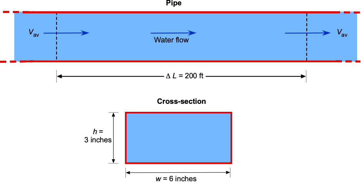
Consider a pump pushing water steadily through a 200-ft-long section of cast-iron pipe, as shown in the figure below. The rectangular cross-section of the pipe has a height of  in and a width of
  in. The internal surface roughness is
  0.006 inches. The volumetric flow rate through the pipe is 0.75 ft s. Assume that the density of the water
  is 1.940 slug ft and its viscosity is 2.1
 slug ft s. Also, assume that entrance effects can be ignored.
-
- Determine the hydraulic diameter of the pipe.
- Determine the average flow velocity through the pipe.
- Determine the Reynolds number
 of the flow in the pipe.
 - Is the flow in the pipe laminar or turbulent? Explain.
- Determine the pipe’s friction factor .
- Determine the pressure drop and head loss
 through the pipe.
- Determine the hydraulic diameter
1. The cross-sectional area of the rectangular pipe is
![\[ A = w \times h = (3.0/12.0)(6.0/12.0) = 0.125~\mbox{ft${^{2}}$} \]](https://eaglepubs.erau.edu/app/uploads/quicklatex/quicklatex.com-c9b8bca325dbde2c4eedc260ac704907_l3.svg "Rendered by QuickLaTeX.com")
so the hydraulic diameter is
![\[ D_h = \frac{4 \times \mbox{Area}}{\mbox{Perimeter}} = \frac{4A}{2 (w + h) } = \frac{2A}{(w + h) } = \frac{2.0 \times 0.125}{(3.0/12.0 + 6.0/12.0)} = 0.33~\mbox{ft} \]](https://eaglepubs.erau.edu/app/uploads/quicklatex/quicklatex.com-d570e54966fd95af774220a571bc9277_l3.svg "Rendered by QuickLaTeX.com")
2. The average flow velocity in the pipe is determined from the volumetric flow rate and the cross-sectional area, i.e.,
![\[ V_{\rm av} = \frac{Q}{A} = \frac{0.75}{0.125} = 6.0~\mbox{ft s$^{-1}$} \]](https://eaglepubs.erau.edu/app/uploads/quicklatex/quicklatex.com-c49b5a811a563f7435f247ffd24fe3b2_l3.svg "Rendered by QuickLaTeX.com")
3. The Reynolds number based on the hydraulic diameter is
![\[ Re_{D_h} = \frac{\varrho_{\rm w} \, V_{\rm av} \, D_h}{\mu_{\rm w}} = \frac{1.940 \times 6.0 \times 0.33}{2.1\times 10^{-5}} = 184,762 \approx 185,000 \]](https://eaglepubs.erau.edu/app/uploads/quicklatex/quicklatex.com-a934daac3553d025e4cad5caf4fa2aa8_l3.svg "Rendered by QuickLaTeX.com")
4. Because the Reynolds number is greater than 2,000, the flow in the pipe will be turbulent.
5. The relative surface roughness is
![\[ \frac{\epsilon}{D_h} = \frac{0.006/12.0}{0.33} = 0.0015 \]](https://eaglepubs.erau.edu/app/uploads/quicklatex/quicklatex.com-6fc61d27231801c8bf2c4690bfa0e1f9_l3.svg "Rendered by QuickLaTeX.com")
Using the Moody chart, the friction factor for this Reynolds number and relative roughness is about 0.023. Minor errors in reading the chart are acceptable.
6. The pressure drop over a pipe length of 200 ft is
![\[ \Delta p = \frac{1}{2} \varrho_ w \, V_{\rm av}^2 \, f \left(\frac{L}{D_h}\right) \]](https://eaglepubs.erau.edu/app/uploads/quicklatex/quicklatex.com-be7d39a4125579eba5c534b94425ec97_l3.svg "Rendered by QuickLaTeX.com")
Inserting the known values gives
![\[ \Delta p = 0.5 \times 1.94 \times 6.0^2 \times 0.023 \left( \frac{200.0}{0.33} \right) = 480.76~\mbox{lb ft$^{-2}$} \]](https://eaglepubs.erau.edu/app/uploads/quicklatex/quicklatex.com-5550a69abbd40699468970b888b51f69_l3.svg "Rendered by QuickLaTeX.com")
The corresponding head loss is
![\[ \Delta h = \frac{\Delta p}{\varrho_w \, g} = \frac{480.76}{1.94 \times 32.17} = 7.79~\mbox{ft} \]](https://eaglepubs.erau.edu/app/uploads/quicklatex/quicklatex.com-ff170b2a08af2cbbe21fbd1a704b4858_l3.svg "Rendered by QuickLaTeX.com")
Worked Example #11
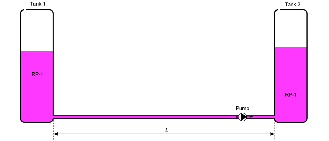
RP-1 rocket fuel will be transferred from one tank to another using a pump with a flow rate of = 52.1 ft per minute. The fuel passes through a 4-inch-diameter steel pipe with a length of 40 ft. The pipe has a roughness, = 0.002 inches. Assume the density of RP-1 is 1.746 slug ft and its viscosity is  slug fts. How much pumping power is required to move the RP-1 along the pipe?
The average flow velocity in the pipe is
![\[ V_{\rm av} = \frac{Q}{A} = \frac{4 Q}{\pi \, d^2 } = \frac{4 \times 52.1 /60 \times }{\pi (4.0/12.0)^2} = 9.95~\mbox{ft s$^{-1}$} \]](https://eaglepubs.erau.edu/app/uploads/quicklatex/quicklatex.com-0b0cb0022f820745ba3cf14449ae888e_l3.svg "Rendered by QuickLaTeX.com")
The Reynolds number based on the diameter is
![\[ Re_{d} = \frac{\varrho \ V_{\rm av} \, d }{\mu_w} = \frac{1.746 \times 9.95 \times 4.0/12.0}{7.4\times10^{-4}} = 7,825 \approx 8,000 \]](https://eaglepubs.erau.edu/app/uploads/quicklatex/quicklatex.com-43b963038212736087b47f16ffa58aa4_l3.svg "Rendered by QuickLaTeX.com")
This result indicates that the pipe flow will be turbulent, so we must refer to the Moody chart to determine the friction factor. The relative surface roughness is
![\[ \frac{\epsilon}{d} = \frac{0.002 }{4.0} = 0.0005 \]](https://eaglepubs.erau.edu/app/uploads/quicklatex/quicklatex.com-1308ab36734afef8782003586123ae18_l3.svg "Rendered by QuickLaTeX.com")
Using the Moody chart, the friction factor is about 0.035. Some minor errors in reading the chart are acceptable. The pressure drop over the 40 ft length of pipe is
![\[ \Delta p = \frac{1}{2} \varrho_ w \ V_{\rm av}^2 \ f \left(\frac{L}{D_h}\right) \]](https://eaglepubs.erau.edu/app/uploads/quicklatex/quicklatex.com-b701e4d0b67d60b1c9a88d0353602c61_l3.svg "Rendered by QuickLaTeX.com")
and inserting the values gives
![\[ \Delta p = 0.5 \times 1.746 \times 9.95^2 \times 0.035 \left( \frac{40.0}{4.0/12.0)} \right) = 363.0~\mbox{lb ft$^{-2}$} \]](https://eaglepubs.erau.edu/app/uploads/quicklatex/quicklatex.com-e382b0a07eafe2e60b01b1a2cd367bcd_l3.svg "Rendered by QuickLaTeX.com")
The corresponding pumping power required is
![\[ P = Q \, \Delta p = (52.1/60) \times 363.0 = 0.57~\mbox{hp} \]](https://eaglepubs.erau.edu/app/uploads/quicklatex/quicklatex.com-93cbb3209e8fd2db5187b2f1cc010ca7_l3.svg "Rendered by QuickLaTeX.com")
Worked Example #12
A liquid rocket fuel system utilizes a high-strength nickel alloy pipe with a diameter of  cm to transport liquid oxygen (LOX) from the tank to the engine. The LOX has a density
  kg m and a viscosity
  Pa s. The mass flow rate of the LOX is
  kg s. Assume that the average roughness of the pipe is 0.04 mm. How much pumping power is required to move the LOX along the pipe?
The average flow velocity in the pipe is
![\[ V_{\rm av} = \frac{\overbigdot{m}}{\varrho \, A_c} = \frac{4 \overbigdot{m}}{\varrho \pi D^2 } = \frac{4 \times 20.0}{1,140.0 \times \pi \times 0.04^2 } = 13.96~\mbox{m s$^{-1}$} \]](https://eaglepubs.erau.edu/app/uploads/quicklatex/quicklatex.com-3846aba2db31db31749babd406d5c9b1_l3.svg "Rendered by QuickLaTeX.com")
The Reynolds number of this flow (based on pipe diameter) is
![\[ Re = \frac{\varrho \, V_{\rm av} \, D}{\mu} = \frac{ 1,140 \times 13.96 \times 0.04}{0.0001947} \approx 3,270,000 \]](https://eaglepubs.erau.edu/app/uploads/quicklatex/quicklatex.com-a9135d517b7036b7eba45ba92581e633_l3.svg "Rendered by QuickLaTeX.com")
This Reynolds number is significantly greater than 2,000, so the flow is in the turbulent regime. The relative roughness is
![\[ \frac{\epsilon}{D} = \frac{0.04}{4.0 \times 10} = 0.001 \]](https://eaglepubs.erau.edu/app/uploads/quicklatex/quicklatex.com-f620e839f71d431c7a02f69fd9e8b050_l3.svg "Rendered by QuickLaTeX.com")
Referring to the Moody chart for = 3,270,000 and = 0.001, then  0.02.
0.02.
The pressure drop along the pipe is
Substituting the numerical values gives
![\[ \Delta p = \frac{1}{2} \times 1,140.0 \times 13.96^2 \times 0.02 \left( \frac{5.0}{0.04} \right) = 277,706.0~\mbox{Pa} \]](https://eaglepubs.erau.edu/app/uploads/quicklatex/quicklatex.com-8dcaf0a793cc2a4ec300028007fe6ea6_l3.svg "Rendered by QuickLaTeX.com")
Therefore, the power required to pump this flow is
![\[ P = Q \, \Delta p = \left( \frac{\overbigdot{m}}{\varrho} \right) \Delta p = \left( \frac{20.0}{1,140.0} \right) \times 277,706.0 \approx 4.87~\mbox{kW} \]](https://eaglepubs.erau.edu/app/uploads/quicklatex/quicklatex.com-b2ee73381d2d17886a142797b393373f_l3.svg "Rendered by QuickLaTeX.com")
Worked Example #13
A steel pipe, 1,000 ft long, has a 15-inch diameter and a 1.5-inch wall thickness. The pipe carries water from a reservoir, and a valve is located downstream of it. When the valve is fully open, the flow rate through the pipe is 23.3 ft/s. If the valve is closed completely in 0.15 seconds, determine the water hammer pressure in the pipe. Assume  = 3.0
= 3.0  lb/in, and
  = 2.8
= 2.8  lb/in, and
  = 1.0. The density of water is 1.94 slugs/ft.
The relevant equation, in this case, for the water hammer pressure in an elastic pipe is
![\[ \Delta p = \varrho \, a \, V_0 = \varrho \sqrt{ \frac{E_c}{\varrho} } V_0 \]](https://eaglepubs.erau.edu/app/uploads/quicklatex/quicklatex.com-283a822a40cd799edbddf169b63139dc_l3.svg "Rendered by QuickLaTeX.com")
where  is the effective bulk modulus of the water in the pipe. The average velocity through the pipe,
  , is related to flow rate, , using
![\[ V_0 = \frac{Q}{A} = \frac{4 Q}{\pi \, D^2} = \frac{4 \times 23.3}{\pi (15.0/12.0)^2} = 18.99~\mbox{ft/s} \]](https://eaglepubs.erau.edu/app/uploads/quicklatex/quicklatex.com-fc78275b7601cb2219eea0484cb9e257_l3.svg "Rendered by QuickLaTeX.com")
The effective bulk modulus is given by
![\[ \frac{1}{E_c} = \frac{1}{E_b} + \frac{D \, K}{E_p \, e} = \frac{1}{3.0 \times 10^5} + \frac{(15.0/12.0) \times 1.0}{2.8 \times 10^7 \times (2.0/12.)} = 3.75 \times 10^{-6} \]](https://eaglepubs.erau.edu/app/uploads/quicklatex/quicklatex.com-02b2cc92ff98123456b416f28cf07c10_l3.svg "Rendered by QuickLaTeX.com")
so that the value of is  lb/in
lb/in . Therefore, the wave propagation speed is
![\[ a = \sqrt{ \frac{E_c}{\varrho} } = \sqrt{ \frac{144 \times 2.67 \times 10^5}{1.94} } = 4,451.8~\mbox{ft/s} \]](https://eaglepubs.erau.edu/app/uploads/quicklatex/quicklatex.com-01c27ff2e0a4f17580bdda395a72b28e_l3.svg "Rendered by QuickLaTeX.com")
and the wave reflection time is
![\[ t_t = \frac{2 L}{a} = \frac{2 \times 1,000}{4,451.8} = 0.45~\mbox{s} \]](https://eaglepubs.erau.edu/app/uploads/quicklatex/quicklatex.com-ed5b2e32d85382e48b5cd8fd890e1548_l3.svg "Rendered by QuickLaTeX.com")
And so with a valve closure time of 0.15 s, then  , this is a sudden closure. Therefore, the water hammer change in pressure will be
![\[ \Delta p = \varrho \, V_0 \, a = 1.94 \times 18.99 \times 4,451.8 = 1.64 \times 10^5~\mbox{lb/ft${^{2}}$} = 1,138.94~\mbox{lb/in${^{2}}$} \]](https://eaglepubs.erau.edu/app/uploads/quicklatex/quicklatex.com-47d840617db93b162f42279bdc48e308_l3.svg "Rendered by QuickLaTeX.com")
