56 Stalling & Spinning
Introduction
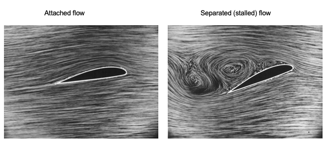
The wings generate the lift on an airplane to overcome the airplane’s weight. Lift production depends on the airplane’s airspeed, the air’s density, the wing’s size (i.e., area), and the wing’s angle of attack. The angle of attack is of particular interest because a wing can only produce lift with good aerodynamic efficiency over a relatively small range of angles of attack before the flow separates from the upper surface and the wing stalls. At low angles of attack, the flow passes smoothly over a wing, as shown in the image below; this aerodynamic condition is the normal mode of flight operation. The highest angle of attack at which a wing can operate is called the stall angle of attack (or simply the stall angle) and corresponds to the angle at which flow separation progresses to the point that it causes a loss of lift.
The onset of flow separation anywhere on a wing will limit its maximum lifting capability; this behavior is also commensurate with increased drag. When a wing fully stalls, there is also a pronounced nose-down pitching moment associated with an aft movement of the center of pressure produced by the effects of the separated flow, as well as significant unsteady flow and buffeting from the creation of turbulence. Therefore, the onset of a stall on a wing usually represents a limiting factor in the operational flight envelope of an airplane and generally sets its lowest controllable airspeed. In some cases, the onset of stall may precipitate a spin, where the airplane enters a rapid downward spiral with the wing in a stalled state. Therefore, it is crucial to understand what a stall is on a wing, how it occurs, and the factors that can affect the onset of the stall.
Learning Objectives
- Understand the fundamental flow physics associated with the onset of flow separation and stall on an airfoil and a finite wing, as well as its implications.
- Know how to calculate an airplane’s stall airspeed under different weight and density altitude conditions and for different maximum lift coefficients.
- Understand the importance of various “high-lift” devices, such as flaps on airplane wings, to raise the maximum lift coefficients and reduce stall airspeeds.
- Appreciate the significance of a spin and why the onset of a stall is a prerequisite to developing a spin.
Stalling Airspeeds & Angles of Attack
In terms of aerodynamics, for vertical equilibrium on an airplane in straight-and-level flight, then
(1) 
where  is the air density in which the airplane flies,
  is the wing area, and
  is the total wing lift coefficient. The assumption is that the main wings generate all lift to overcome the weight
  , even though the horizontal tail may carry some small lift (positive or negative).
Stall Airspeeds
For estimating the stall airspeeds of an airplane, i.e., before verification by flight testing, it is normal to assume that only the main wings carry the lift of the entire airplane. For the density of the air, recall that  where the value of the density ratio,
  , comes from the ISA model, so an alternative variant of Eq. 1 is that
(2) 
Rearranging this equation gives the lift coefficient needed for the wing at a given flight airspeed, airplane weight, and operational density altitude (i.e., air density), i.e.,
(3) 
The ratio of an airplane’s weight to its lifting wing area,  , is known as wing loading. Notice also that the lift coefficient is proportional to wing loading but decreases with the square of the airspeed. The lift coefficient also increases with density altitude, i.e., lower values of , for a given airspeed and flight weight.
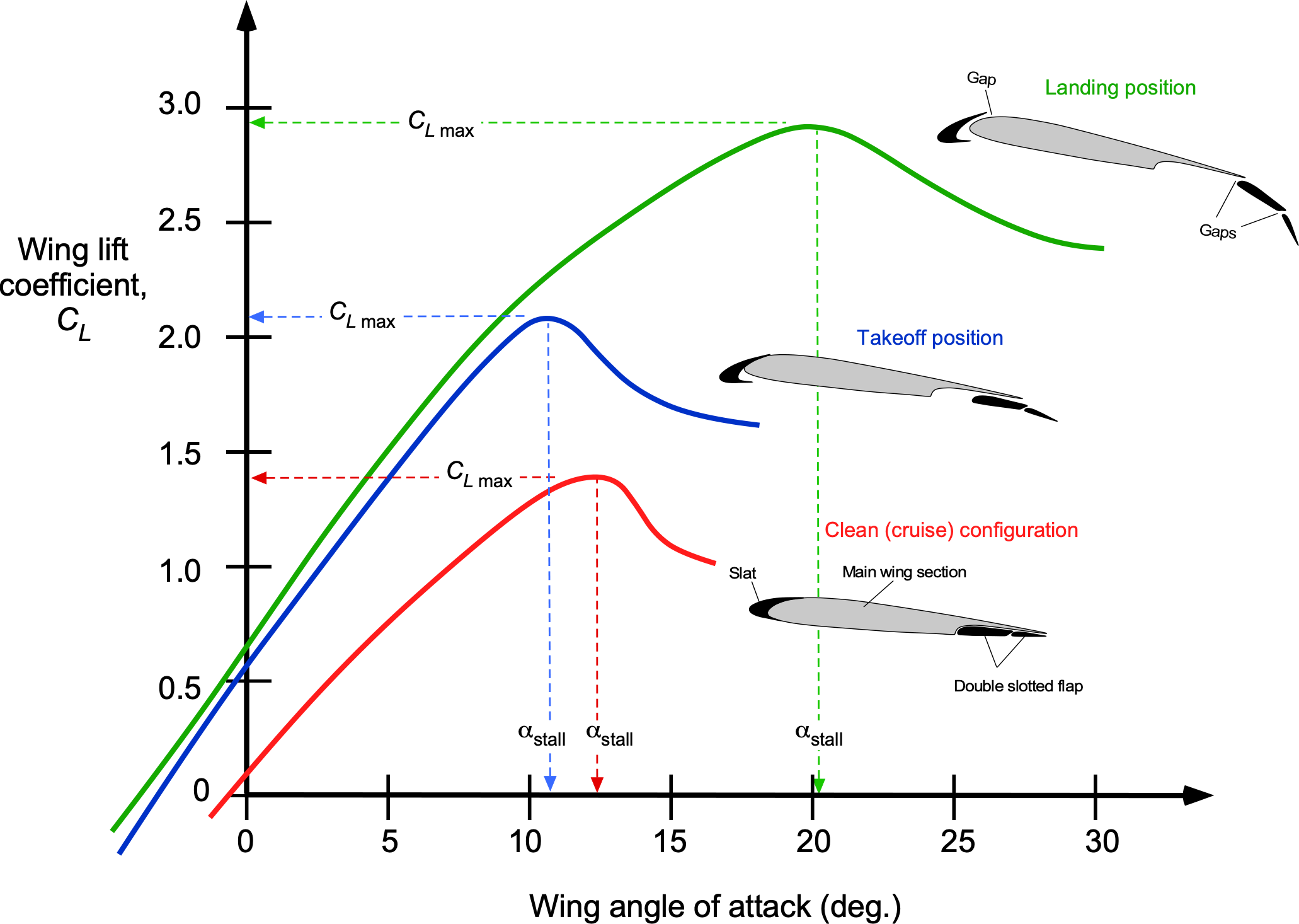
The minimum airspeed that allows the airplane to fly is called the stalling airspeed, which corresponds to the angle of attack and lift coefficient at which the wing will stall. To understand why this condition is important, consider the typical relationship between the lift coefficient and angle of attack, as shown in the figure below, which also accounts for the effects of high-lift devices such as flaps and leading-edge slats. The maximum lift coefficient is  , so it is apparent that increases from about 1.4 for the baseline wing in the clean configuration to nearly 3.0 with full flaps and the leading edge slats extended.
Although the value of may not be exactly known (i.e., predictable) for any wing without a wind tunnel or flight testing, the corresponding stall airspeed in straight and level unaccelerated flight can be solved by using
(4) 
Conversely, if the stall airspeed of the wing is known, which would need a careful measurement of the equivalent and true airspeeds (not the indicated airspeed) at which stall occurs, then it is possible to calculate the corresponding of the wing, i.e.,
(5) 
Check Your Understanding #1 – Calculation of stall airspeed
An airplane has a wing with a maximum lift coefficient, , of 1.7. The in-flight weight, , is 20,000 lb, and the wing area, , is 340 ft2. The aircraft is in steady, unaccelerated flight at an altitude where the density ratio, , is 0.7385. Calculate the stall airspeed of the airplane.
Show solution/hide solution.
The stall airspeed is given by
![\[ V_{\rm stall} = \sqrt{ \frac{2}{\varrho_0 \, \sigma } \left( \frac{W}{S} \right) \frac{1}{C_{L_{\rm max}} }} \]](https://eaglepubs.erau.edu/app/uploads/quicklatex/quicklatex.com-5dd637c14b5958beb562c73417073881_l3.svg "Rendered by QuickLaTeX.com")
Inserting the known values gives
![\[ V_{\rm stall} = \sqrt{ \frac{2}{0.002378 \times 0.7385} \left(\frac{20,000}{340.0} \right) \frac{1}{1.7} } = 198.5~\mbox{ft/s} = 117.6~\mbox{kts} \]](https://eaglepubs.erau.edu/app/uploads/quicklatex/quicklatex.com-59754a5c754a16e34d74944f9157511b_l3.svg "Rendered by QuickLaTeX.com")
Stall Angle of Attack
The flow is fully attached to the wing in the linear region of the lift curves shown in the previous figure. In this region, the relationship between the lift coefficient and the angle of attack can be written as
(6) 
where  is the lift curve (in appropriate units of per degree or radian). The parameter
  in Eq. 3 is called the zero-lift angle of attack. It reflects that the zero lift coefficient will be obtained when the wing is at a small negative angle of attack, which is typical for a wing with normal amounts of camber. It will be noticed. However, the value of becomes increasingly negative by applying flaps and then with flaps and slats together.
The airspeed in level flight that corresponds to a given lift coefficient can be determined, i.e.,
(7) 
Further, based on a linear lift-curve slope assumption, i.e.,  , then airspeed can also be related to the angle of attack, i.e.,
(8) 
and so the angle of attack to airspeed, i.e.,
(9) 
This latter result is beneficial for piloting because the pilot generally monitors the airplane’s airspeed, not the wing angle of attack. However, some high-performance airplanes and airliners may have an angle of attack sensor and cockpit indicator to help avoid a stall.
The value of for a high aspect ratio wing at low flight Mach numbers (below 0.3) is typically about 0.1 per degree or 5.7 per radian, but somewhat larger at higher subsonic Mach numbers, i.e., according to the Glauert rule. Decreasing the aspect ratio of the wing will also reduce the value of , but the actual value may not be known precisely a priori before the airplane is built and flown, even though it can be estimated based on mathematical aerodynamic models and perhaps with the aid of wind tunnel testing.
At higher angles of attack, the lift coefficient reaches a maximum value and then decreases markedly because of the onset of flow separation and stall. For example, for a plain wing of moderate to high aspect ratio at low Mach numbers (i.e., one without any high lift devices), the maximum lift coefficient, , is typically between 1.4 and 1.6. This result means that the corresponding maximum angle of attack of the wing before stall (based on typical values of lift-curve slope) at the low subsonic Mach numbers typical of takeoff and landing will be between 14 and 16. However, the figure above shows that for a wing with high-lift devices deployed, values of can be much higher. However, also note that the angle of attack for stall can be lower or higher, depending on how the high-lift device(s) modify the wing camber and, consequently, the zero-lift angle of attack, , which varies with the wing.
Load Factor
Although airspeed is related to the stall angle of attack, it is important to appreciate that a wing will stall at any airspeed if the angle of attack reaches the stall angle. For example, if the airplane is maneuvering and attains a steady load factor  such that now
  , then the new stall airspeed would be
(10) 
which shows that the stall airspeed increases with the square root of the load factor, i.e.,
(11) 
where  is the stall airspeed for any load factor,
  , and
, and  is the load factor in level, unaccelerated flight, i.e.,
  . It will be apparent that the stall angle of attack for a given wing in a given configuration, however, is the same regardless of the load factor, and it is not a function of airspeed other than through the effects of Mach number and/or Reynolds number.
Summary of Effects on Stall Airspeed
In summary, from the preceding, it can be concluded that:
- Stall airspeed will increase as the airplane’s weight increases.
- Stall airspeed increases with increasing density altitude, i.e., with lower air density.
- Stall airspeed will decrease with increasing values of wing , which could be achieved by deploying wing flaps and/or leading-edge slats.
- Stall airspeed will decrease with increasing wing area.
- Stall airspeed will increase with an increasing load factor.
General Flow Physics of Stall
At higher angles of attack before stall, the adverse pressure gradients produced on the wing’s upper surface result in a progressive increase in the thickness of the boundary layer. This causes some deviation from the linear lift versus angle of attack behavior, initially manifesting as a “rounding” of the lift curve, as shown previously. With a further increase in the angle of attack, the flow will separate from the upper surface, causing a stall.
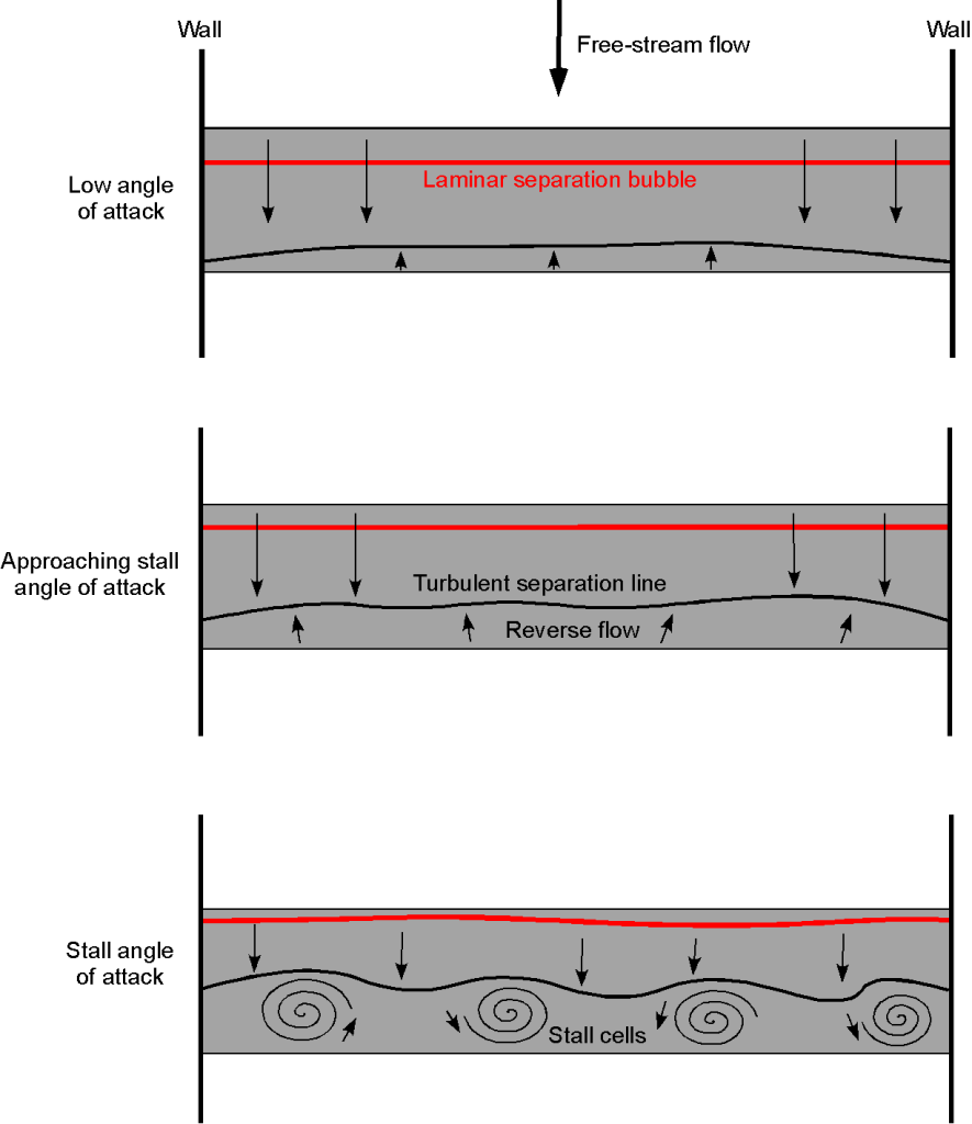
On many wings and airfoils, the onset of a stall occurs gradually with an increasing angle of attack, as illustrated in the figure below, known as a trailing-edge stall. However, on other wings, particularly those with sharper leading edges found on high-speed aircraft, flow separation may occur quite suddenly, such as when reaching a critical angle of attack, typically referred to as a leading-edge stall.
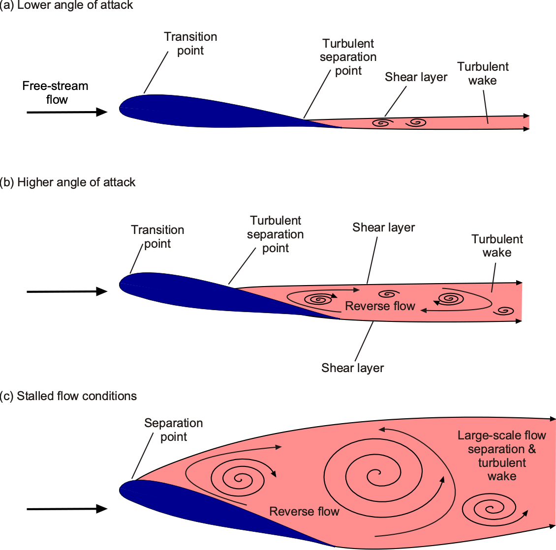
After the stall, much less lift is generated on the wing, and drag is substantially greater. Also, under these separated flow conditions, steady flow no longer prevails, and turbulence is shed into the wake, manifesting as buffeting. For example, measurements on stalled wings in the wind tunnel will generally show large fluctuating forces and pitching moments when the flow separates.
Two-Dimensional Stall Characteristics
Much of the detailed understanding of the aerodynamics of wings and wing sections comes from testing in wind tunnels, where the effects of the wing section (i.e., the airfoil shape), wing aspect ratio, and wing planform are the most important. In their compendium of measurements, Abbott and von Doenhoff have documented a summary of the characteristics of many airfoil sections made at Reynolds numbers ranging from 3 to 9 million and Mach numbers up to 0.2, which contains a wealth of measurements for engineers.
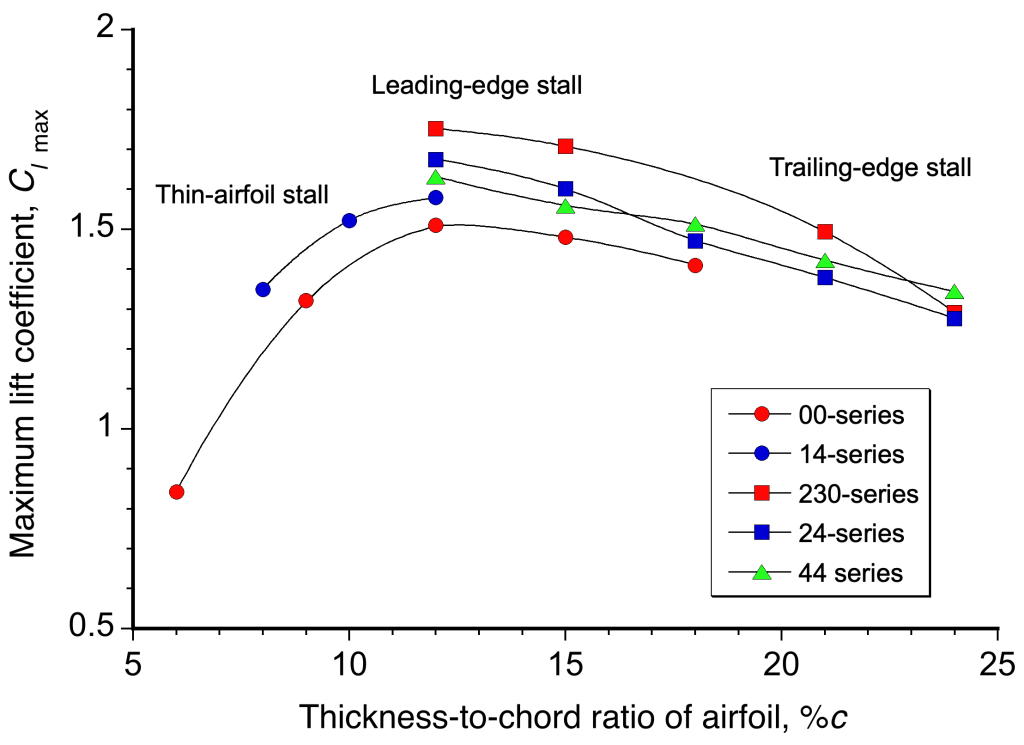
It has been found that airfoils generally fall into three categories of static stall: thin-airfoil stall, leading-edge stall, and trailing-edge stall. Abbott & von Doenhoff demonstrate that thin-airfoil and leading-edge stalls are abrupt stall types that can be sensitive to changes in airfoil shape, whereas trailing-edge stalls are a more gradual type of stall and less sensitive to shape changes. Most conventional subsonic wings fall into the trailing-edge stall category at low to moderate Mach numbers, although the more abrupt form of a leading-edge stall is not uncommon. However, for supersonic wings with relatively sharp leading edges, their stall characteristics at low airspeeds are usually an abrupt leading-edge type of stall.
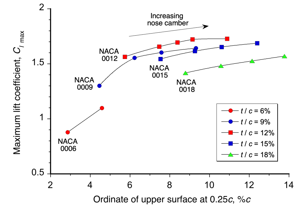
The figure below summarizes measurements showing the combined effect of thickness and camber on the  of an airfoil. Clearly, “thin” airfoils (low values of the thickness-to-chord ratio of between 4% and 8%) produce much lower values of . Still, it is interesting to note that increasing thickness above 12% begins to reduce the value of . The best airfoils in terms of attaining the highest have a thickness-to-chord ratio between 12% and 15%, which is common on wings used for airplanes.
 of an airfoil.
Using some nose camber for a given thickness-to-chord ratio is also desirable in increasing , as shown in the figure below. However, there is a point of diminishing returns in that some slight camber over the nose region of an airfoil is desirable, but too much gives only minor gains in . Indeed, using significant nose camber is usually undesirable for two reasons. First, large amounts of camber increase the pitching moments on the airfoil section and the wing as a whole, which is not always desirable. Second, too much camber is associated with increased profile drag, which is never a good outcome.
 of an airfoil.
The of an airfoil section also reduces with increasing freestream Mach number, as shown in the figure below. This behavior is because increasing the Mach number makes the airfoil’s pressure gradients more adverse, increasing the boundary layer thickness on the upper surface at a lower angle of attack. This effect reduces the value of and the corresponding stall angle as the Mach number increases. Notice also the effects of Reynolds number (chord-based), for which lower Reynolds numbers will result in lower values of for a given Mach number.
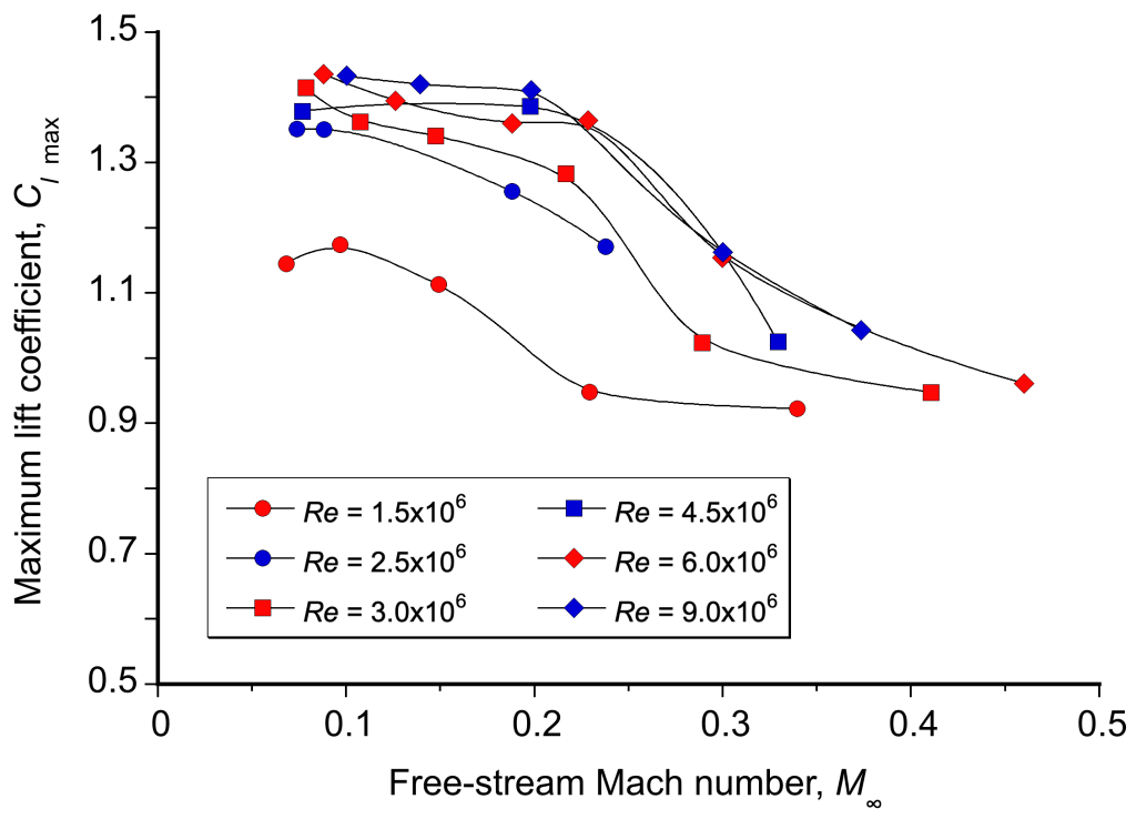 of an airfoil at different chord Reynolds numbers.
Therefore, in addition to the primary factors that have been discussed that will affect the stall airspeed, the stall angle of attack and corresponding airspeed will generally:
- Decrease with increasing flight Mach number.
- Decrease with decreasing chord-based Reynolds number.
Three-Dimensional Stall
The effects of wing planform (e.g., taper) and twist (wash-out) also affect the local lift coefficient distribution along the wing (i.e., the distribution of  along the span of the wing) and also the total attainable maximum lift coefficient. Therefore, if the local is higher at some point on the wing than at another, the wing is more likely to stall at this location.
While no complete generalization of all the possible results is available for wings, it has been found that higher aspect ratio wings tend to reach higher overall maximum lift coefficients. However, too much planform taper can reduce the wing’s maximum lift coefficient. Likewise, too much sweepback also tends to decrease the maximum attainable lift. Both effects are predictable using various types of aerodynamic theories.
The primary challenge in wing design is that at the point of stall, a finite wing often develops complex three-dimensional flow patterns, as illustrated in the images below, which are based on wind tunnel flow visualization. Sometimes, the pattern is not symmetrical between a wing’s left and right side panels, which, in practice, produces a rolling moment on the airplane and a departure from controlled flight. In a worst-case scenario, the airplane may develop a spin, taking a significant altitude to recover from (see later).
The three-dimensional stall developments on wings can be studied during flight testing by placing strips of yarn called “tufts” all over the wing’s upper surface. The tufts are arranged in orderly rows, both spanwise and chordwise, along the wing, as shown in this video. It will be seen that when the tufts are blown straight back, the flow is fully attached. However, suppose the tufts change direction and lift from the surface. In that case, the flow at those locations is inevitably separated, which is likely an indicator of the incipient stall on the entire wing.
The stall patterns that develop on any given wing depend on numerous factors; however, some general observations have emerged, as illustrated in the schematic below. For rectangular wings, the stall will generally start at the root of the wing and work forward and outward toward the mid-span. This behavior is a desirable stall pattern on a wing because the onset of flow separation causes some buffeting, and the pilot will recognize the stall onset before it progresses too far. The airplane also tends to pitch down naturally at the stall, reducing the wing’s angle of attack and suppressing further stall developments. Finally, the wing’s outer parts have a fully attached flow, so there will be no tendency for the airplane to roll, and the ailerons will be fully effective.
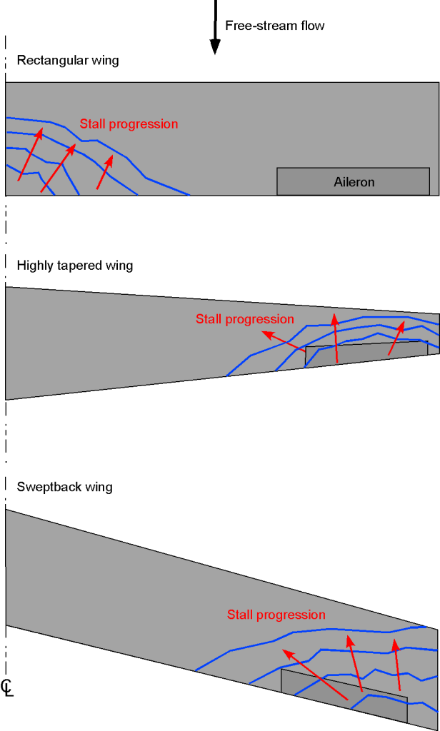
A highly tapered wing has the opposite problem in that the wing tips will tend to stall first. With swept wings, the tips also tend to stall first. In these cases, the aileron effectiveness will be reduced because of the separated flow, and the airplane will often tend to show uncommanded rolls to the left or right. Indeed, in this case, applying controls to correct the roll may exacerbate the stall, and the airplane may experience a control reversal; for example, if the airplane rolls to the right, using regular corrective control inputs can make the roll to the right much worse.
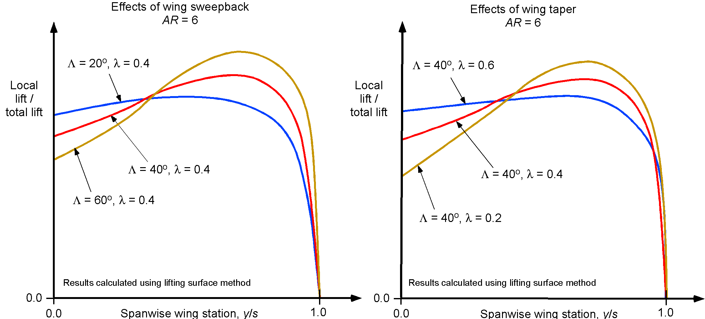
As previously mentioned, large amounts of wing sweepback, which is used to delay the onset of compressibility effects to higher cruise airspeeds, are also known to produce stall toward the wing tips, a concern in the design of commercial airliners. There are two main reasons why swept wings tend to stall first at their tips. First, sweepback alone produces a spanwise distribution of the local lift coefficient biased toward the wing tips. The second is that the wing taper elevates the lift coefficients at the wing tips.
To establish where a wing will stall first, the product of the local section lift coefficient and the wing chord at that position can be divided by the product of the total wing lift coefficient and the mean aerodynamic chord, as shown in the graphs below. Where the resulting values are highest, the wing is most likely to stall first. Using too much planform taper only exacerbates this effect of increasing the lift coefficients at the wing tip, making the wing more likely to stall there. However, the consequences can be mitigated to some extent by using wing twist (wash-out) and careful use of leading-edge camber.
At higher angles of attack, sweepback tends to encourage the boundary layer to grow thicker in the spanwise direction, thus making it more susceptible to separating at the wing tips. Usually, the wing is carefully designed to minimize such tendencies, but other steps are generally necessary. For example, various fences and vortex generators are often used to help maintain attached flow. Additionally, some commercial airplanes feature “auto-slats” that automatically extend when the wing approaches the stall, thereby preventing the stall from developing.
Importance of High-Lift Devices
Airplane wings are typically designed for optimal efficiency in cruising flight conditions. In fact, on commercial transport airplanes, the supercritical wing is explicitly intended to be efficient at transonic flight conditions. However, relatively thin, swept wings tend to have much poorer aerodynamic performance at lower airspeeds and Mach numbers. In the “clean” condition, the airplane exhibits relatively high stalling airspeeds and is susceptible to adverse stall qualities.
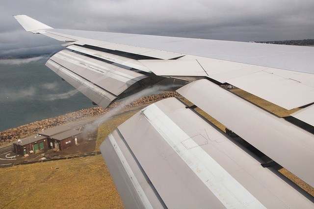
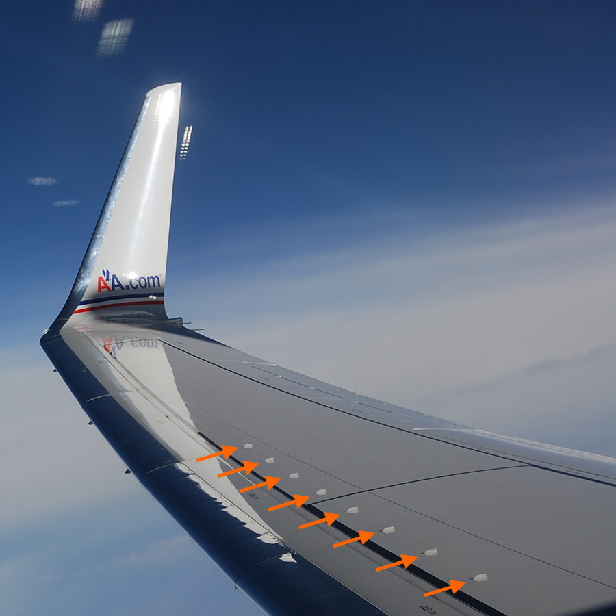
However, as previously explained, it is possible to increase the maximum lift coefficient of a wing and reduce the stall airspeed by using high-lift devices such as trailing-edge flaps and leading-edge slats. The photo below shows the triple-slotted trailing edge flap system in the fully deflected landing configuration. Notice also the condensation trails marking the locations of trailing vortices from the side edges of the flaps and the inboard aileron. The main advantage of reducing stall airspeeds is that the airplane can fly at lower airspeeds, significantly reducing takeoff and landing distances. Of course, nearly every type of airplane can benefit from using high lift devices to lower its stall airspeed and reduce its takeoff and landing distances.
The figure below shows a schematic of a wing section with high-lift devices. Usually, the flaps operate in conjunction with the leading-edge slats, if available. In many cases, the flaps are designed to deflect rearward and downward, a configuration known as Fowler flaps, which increases the effective area of the wing and its camber in the region of the flaps.
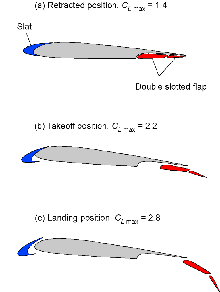
The flaps and slats are partly deflected for takeoff to reduce the takeoff airspeed and takeoff distance. After takeoff, the airplane’s flaps are progressively retracted as airspeed increases, and the slats are also retracted. For landing, the flaps are fully deflected; they are gradually extended in stages as the airplane descends from altitude and slows down to its final landing approach airspeed. The extra drag from full flap deflection helps slow the airplane down to landing airspeeds and steepens its final approach angle to the runway, both of which aid the pilot in a successful landing.
Leading-edge slats usually work in synchronization with the flaps. Like the trailing edge flaps, their purpose is to increase the wing’s maximum lift and angle of attack capability before it stalls, allowing the airplane to fly at lower airspeeds. The usual types of slats initially move forward and downward, and increase the camber of the wing section. When fully deployed, they also open up a small gap between the slats and the leading edge of the main wing. This gap is critical because it helps to energize the boundary layer on the wing’s top surface. Other leading-edge devices include Kruger flaps, which rotate forward to increase the wing’s leading-edge camber; such devices are often found on the inboard parts of wings, such as on the Boeing 747. Such devices are highly effective in increasing the attainable maximum lift coefficient and angle of attack before the wing stalls.
While flaps by themselves are effective in increasing , the use of flaps and slats together may increase to values of over 3.0. Consequently, if the slats and flaps are both fully deployed, the airplane can typically fly at airspeeds that are 50% less than those without them, i.e., compared to flying in the clean condition with flaps and slats retracted. Additionally, using flaps and slats substantially alters the wing’s camber, which modifies the zero-lift angle of attack and the shape of the lift curve. In some cases, the system’s lift-curve slope may change, especially with the highly effective wing camber introduced by the slats.
Check Your Understanding #2 – Calculation of stall airspeeds with flaps
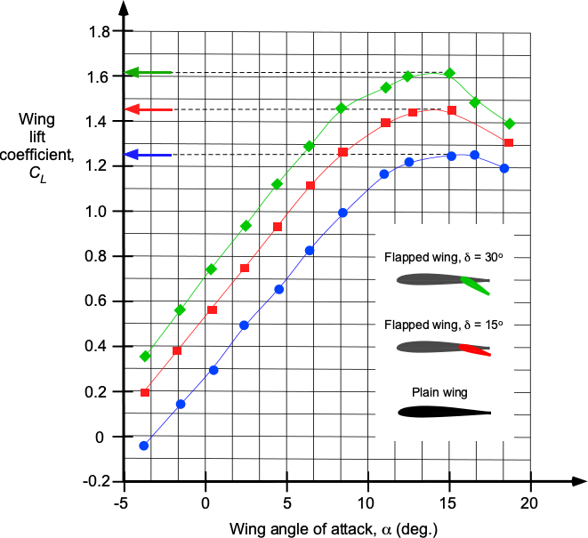
Calculate the stall speeds for a Cessna 402 in knots for flap deflection angles of 0o, 15o, and 30o. The lift characteristics of the wing are shown in the graph below. The airplane has a wing area, , of 255.8 ft2, and weight, , of 6,300 lb. Assume standard MSL ISA conditions.
Show solution/hide solution.
The stall speed is determined using
In this case,
![\[ V_{\rm stall} = \sqrt{ \frac{2}{0.002378} \left( \frac{6,300}{255.8} \right) \frac{1}{C_{L_{\rm max}} }} = \sqrt{\frac{20713.7}{C_{L_{\rm max}}} } \]](https://eaglepubs.erau.edu/app/uploads/quicklatex/quicklatex.com-bacdcf8b0ba91919519aa72d70b74afc_l3.svg "Rendered by QuickLaTeX.com")
The values of must now be estimated by reading the graph.
- For the plain wing with the flaps up,
 . Therefore,
![\[ V_{\rm stall} = \sqrt{\frac{20713.7}{C_{L_{\rm max}} }} = \sqrt{\frac{20713.7}{1.26} }= 128.2~\mbox{ft/s} = 76.0~\mbox{kts} \]](https://eaglepubs.erau.edu/app/uploads/quicklatex/quicklatex.com-31941ba956965001fc8ea3413dabccd5_l3.svg "Rendered by QuickLaTeX.com")
- For 15 of flaps, then
 . Therefore,
![\[ V_{\rm stall} = \sqrt{\frac{20713.7}{C_{L_{\rm max}} }} = \sqrt{\frac{20713.7}{1.45}} = 119.5~\mbox{ft/s} = 70.8~\mbox{kts} \]](https://eaglepubs.erau.edu/app/uploads/quicklatex/quicklatex.com-5da898ae5802cb149338812ba4c8c1b2_l3.svg "Rendered by QuickLaTeX.com")
- For 30 of flaps, then
 . Therefore,
![\[ V_{\rm stall} = \sqrt{\frac{20713.7}{C_{L_{\rm max}} } }= \sqrt{\frac{20713.7}{1.61}} = 113.4~\mbox{ft/s} = 67.2~\mbox{kts} \]](https://eaglepubs.erau.edu/app/uploads/quicklatex/quicklatex.com-d951eafae91c93cdf443e0e46f6c6a82_l3.svg "Rendered by QuickLaTeX.com")
Stall Control Devices
Because the effects of a stall on a new airplane are not entirely predictable in advance of the first flight, the stall is carefully examined during flight testing. This is done to determine the stall airspeeds and stall qualities, which refer to how the aircraft feels or “handles” to the pilot at the point of stall. Unfortunately, not all aircraft are created equal in this regard.
Some aircraft have been found to experience undesirable flight characteristics near stalls, such as uncommanded rolling to the left or the right. For flight safety, it is desired to have a recognizable and repeatable stall with no adverse characteristics; this outcome would be considered good or acceptable handling qualities at the point of stall for aircraft certification. In some cases, “stall fixes” are necessary to provide the airplane with predictable and repeatable stall characteristics.
Vortex Generators
Even a casual observation of the wing on a modern airliner reveals numerous regions where small “vanes” are attached to the wing surface, as shown in the photograph below. These devices are known as vortex generators, or VGs. They are designed to create small vortices to energize the boundary layer flow and keep the flow attached to the wing at higher angles of attack. While the VGs create some drag, the drag is more than offset by the maximum lift benefits.
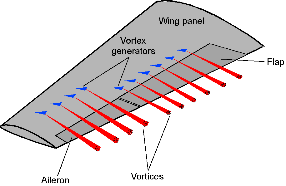
The VGs are typically small, angled plates set at a steep angle to the flow, often resembling little delta-shaped half-wings, which generate flow separation that rolls up into a concentrated vortex, as illustrated in the schematic below. This vortex is similar to a tip vortex, but it is much smaller and mixes with the thickened boundary layer. The consequence is that the boundary layer profile, on average, becomes “energized” and is less susceptible to flow separation. The penalty, however, is a slight increase in drag.
Stall Strips
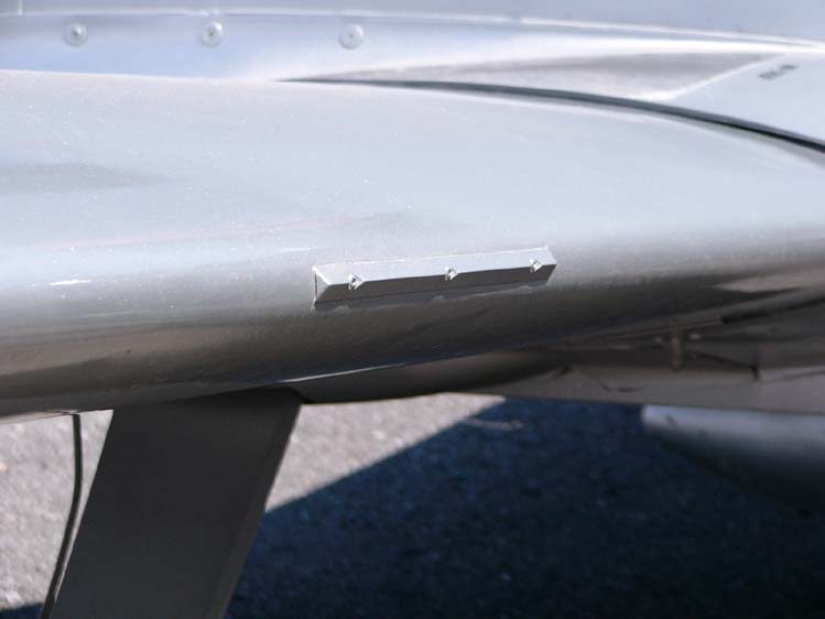
It may seem odd to force a wing to stall, but that is precisely the purpose of stall strips or airflow disruptors. A photograph of a stall strip is shown below, and they are relatively common on many types of aircraft, from small general aviation airplanes to commercial jets to fighter aircraft. The strips are usually a few inches long and perhaps 1/4 inch (6 mm) in height.
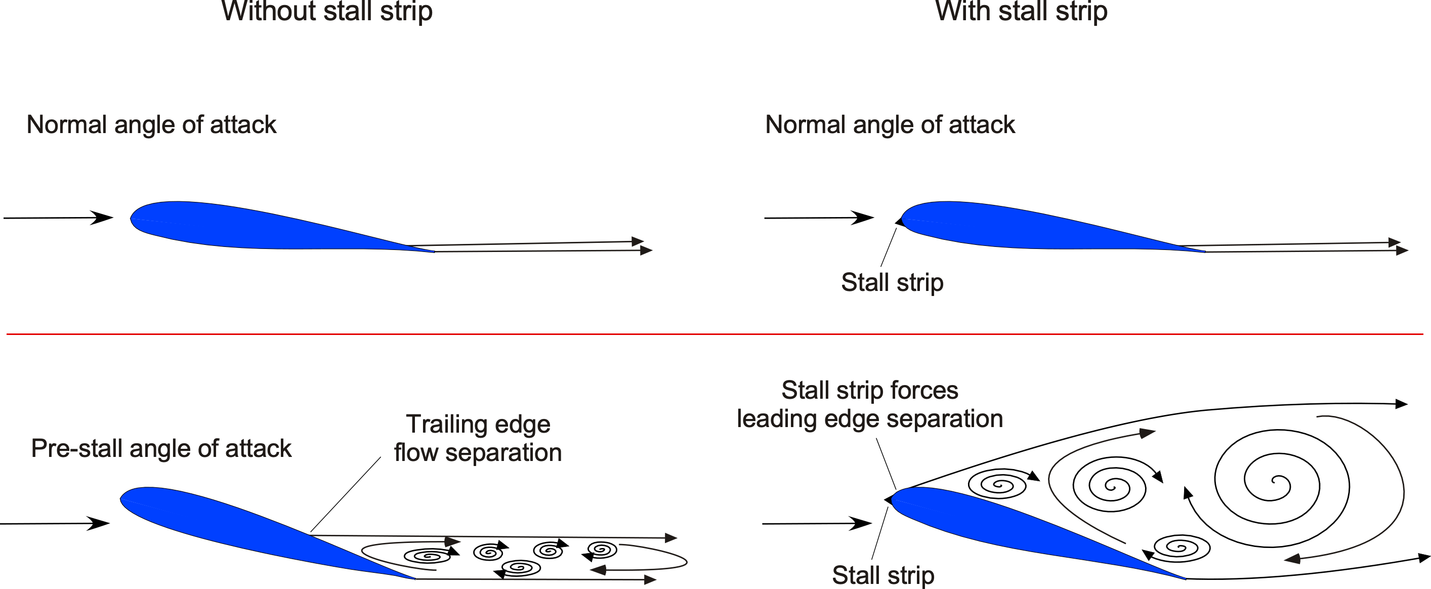
Stall strips are used to promote flow separation at specific locations on the wing during high-angle-of-attack flight, thereby improving the stall qualities of the airplane. They are typically employed in pairs symmetrically distributed on both the left and right wings’ inboard sections, but not always. The usual approach in flight testing is to place the stall strips on the wing’s leading edge, where the desired outcomes are realized, i.e., to force stall to occur at that point on the wing, as suggested in the figure below. On many propeller-driven airplanes, the stall strips are placed at different locations to account for the asymmetric flow produced on the wing by the propeller(s) wake swirl.
Many aircraft have been built and flown only to discover that their stall qualities and high-angle-of-attack flight characteristics require revision. The solution typically combines stall strips and vortex generators, although more drastic measures may be necessary in some cases. Stall strips are typically positioned near the root of the wing to induce flow separation to occur there first. Then, vortex generators are simultaneously applied over the outboard wing panels, improving the airplane’s stall characteristics.
Wing Fences
Wing fences, also known as boundary layer or stall fences, are fixed aerodynamic devices that project perpendicular to aircraft wings and wrap around the leading edge, as shown in the schematic below. With their highly swept wings, many early jet aircraft used fences to control wing stalls, often resulting in undesirable flight characteristics. Some wings may have several fences, which reflects the difficulties in correcting the stall qualities of some swept-wing designs.
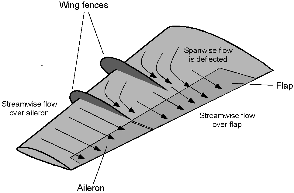
If there is any significant spanwise flow along the wing, the boundary layer thickness can grow toward the wing tips without the fences. The consequence is reduced aileron effectiveness, increased tendency for the wing tips to stall first, and susceptibility to control reversal and spins. The fences limit the spanwise airflow along the wing, directing the flow over the control surfaces and preventing premature boundary layer growth and stall.
Wing Leading Edge Modifications & Cuffs
Leading-edge airfoil modifications can be employed to improve the stall characteristics and low-airspeed performance of a wing. These modifications are particularly valuable in aircraft that operate in demanding flight regimes, such as short takeoff and landing (STOL) operations and agricultural aviation. One widely used passive device is the leading edge cuff, which consists of a fixed modification to the wing’s leading edge, as shown in the figure below. The cuff typically introduces a thickened and slightly drooped nose profile, altering the airfoil geometry. This results in an increased maximum lift coefficient and delays stall onset in the modified region.
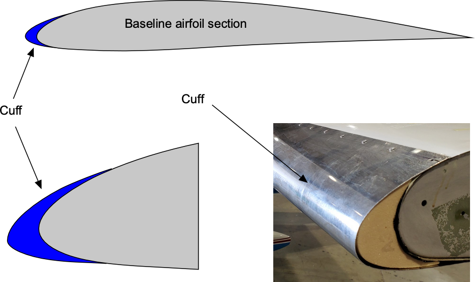
Leading-edge cuffs differ from other high-lift or stall-control devices in that they are entirely passive and structurally fixed, unlike slats. Their simplicity and reliability make them exceptionally well-suited for retrofit applications. However, they often impose a modest drag penalty in cruise flight, as the increased nose camber and thickness of the modified section increase profile drag. Cuffs have been widely used in both original aircraft designs and aftermarket retrofit kits. Aircraft such as the Cessna 172 and 182 have been equipped with cuff modifications, including those offered through Robertson STOL kits, to improve stall behavior and enhance controllability during low-airspeed flight operations.
Spinning
A spin can develop as a consequence of an asymmetric stall, which causes the airplane to rotate about a vertical axis, creating a steep, spiraling, nose-down flight path, as shown in the figure below. While spins can be intentionally provoked on airplanes, such as during flight demonstrations and pilot training, inadvertent spins are generally considered dangerous.
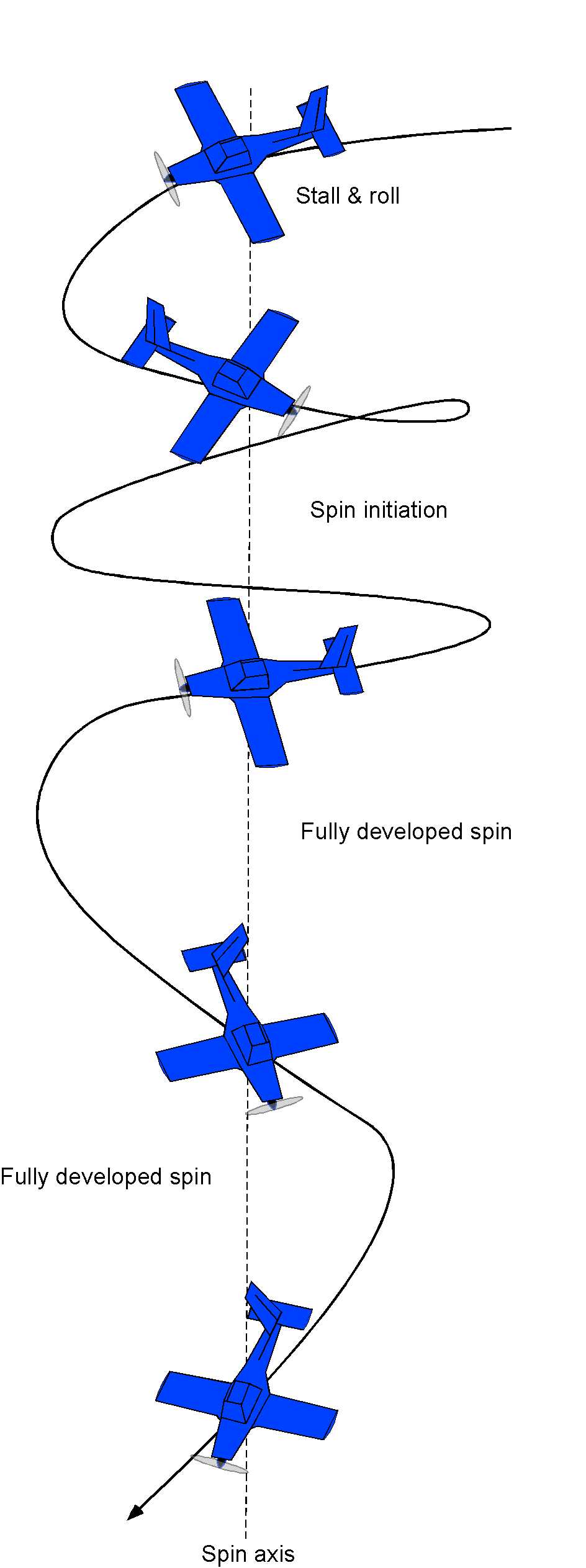
In a spin, the wings are stalled and operate at a high angle of attack, even though the airplane’s attitude is distinctly nose-downward. Recovery from a spin requires counterintuitive control inputs from the pilot, which include pushing forward on the control stick to lower the angle of attack and unstall the wing, while simultaneously using the opposite rudder to the direction of the spin to stop the rotational motion. The rapid rotation about the vertical axis and the nose-down attitude can disorient a pilot, and many “stall/spin” accidents have occurred.
Stall development is a prerequisite to a spin, so stall avoidance will generally prevent an airplane from spinning. Modern commercial airplanes have sophisticated stall warning and stall avoidance systems, so the likelihood of such airplanes inadvertently developing a stall or a spin is exceptionally remote. Nevertheless, their stall characteristics are always carefully explored during flight testing.
Smaller airplanes, however, generally do not have such stall avoidance systems. Therefore, FAA certification standards for smaller civil airplanes with a maximum takeoff weight of up to 12,500 lb require that they demonstrate stalls and spins. Such airplanes must demonstrate a full recovery from stalls and a one-turn spin, utilizing the regular use of flight controls. If intentional spins are to be allowed by certification, then the airplane must demonstrate a six-turn spin. Many GA airplanes are certified for spins when operated in the utility category, which typically means a reduced gross weight and a forward center of gravity position. Spin testing for certification is a potentially dangerous activity, so the test airplane will usually be equipped with some secondary spin-recovery device, such as a tail parachute.
Summary & Closure
Determining the stall characteristics of an airplane is critically important because the airplane will be flown near stalled conditions during takeoff and landing. While much can be done at the design stage to estimate stall airspeeds, both in the “clean” condition (with flaps and slats retracted) and in the “dirty” state (with flaps and slats deployed along with the undercarriage), the stall airspeeds must be confirmed.
In addition to knowing the stall airspeed and onset characteristics, it is essential to understand the recovery characteristics of an airplane during a stall. A well-designed airplane should have a straightforward and uncomplicated stall recovery procedure, which a pilot with appropriate training and skill can execute. The recovery characteristics should be consistent and repeatable regardless of the airplane’s altitude, airspeed, and load factor. Flight test data must demonstrate that the stall recovery procedure is effective and reliable and that the airplane has no dangerous stall-related behavior, such as an uncontrollable spin or an uncommanded roll. Overall, an airplane’s stall characteristics and recovery must be carefully studied and evaluated to ensure that the airplane is safe to fly in all conditions.
Vortex generators and/or stall strips can often improve unacceptable stall qualities. While a spin is not a dangerous maneuver in itself, an airplane’s inherent tendency to spin near the point of the stall is an unacceptable flight characteristic that needs to be mitigated before it can be considered safe to fly by an average pilot and meet FAA certification requirements.
5-Question Self-Assessment Quickquiz
For Further Thought or Discussion
- According to published sources, the Helio Courier airplane’s stall airspeed is reported to be only 23 kts. Do you think this sounds reasonable, and why?
- Another device sometimes used to control an airplane’s stall characteristics is a “wing fence.” Research these devices to understand how they work.
- A Boeing 767 loses the ability to lower the leading-edge slats for landing. Wing flaps are not affected. If the reduction in the of the wing is 30% without using the slats, estimate the percentage increase in the landing airspeed of the airplane. Make any reasonable assumptions you feel are needed.
- Research the internet and analyze a historical aviation incident involving a stall or spin. What were the contributing factors, and what lessons can be learned from the event?
- A new airplane is found to have an undesirable stall characteristic that causes it to roll consistently to the left with a tendency to spin as it approaches the stall. Suggest some options as to how this adverse flight characteristic may be mitigated.
- How might flight simulators contribute to pilot training in preventing and recovering from stalls and spins?
- What regulatory measures are in place to ensure that pilots receive adequate training in stall and spin recovery? How do aviation authorities enforce compliance with these training requirements?
- Conduct research on the internet to determine if any advanced technologies or systems can help prevent stalls or spins in modern aircraft. How might fly-by-wire systems contribute to the prevention of stalls and spins?
Other Useful Online Resources
To understand more about stalling and spinning, follow up with some of these online resources:
- A NACA film of the airflow about airfoils with flaps and slats operating in stall.
- The use of tufts to examine stall and spin patterns on the wing.
- A video about what a spin is.
- Stall to spin recovery video.
- Video showing the anatomy of a Cirrus stall accident.
- An explanation of unsteady stall or dynamic stall.
- Video of a Boeing 747 stalling.
- Video of stalling in an Airbus A310.
- Boeing 737-400 test flight with wing stalls.
