60 Worked Examples: Anatomy, Regulations & Structures
Worked Example #1
Based on the photograph below, identify the category and class of aircraft. Then, using the letters in the image, identify each part of the aircraft and briefly explain the purpose and function of each part.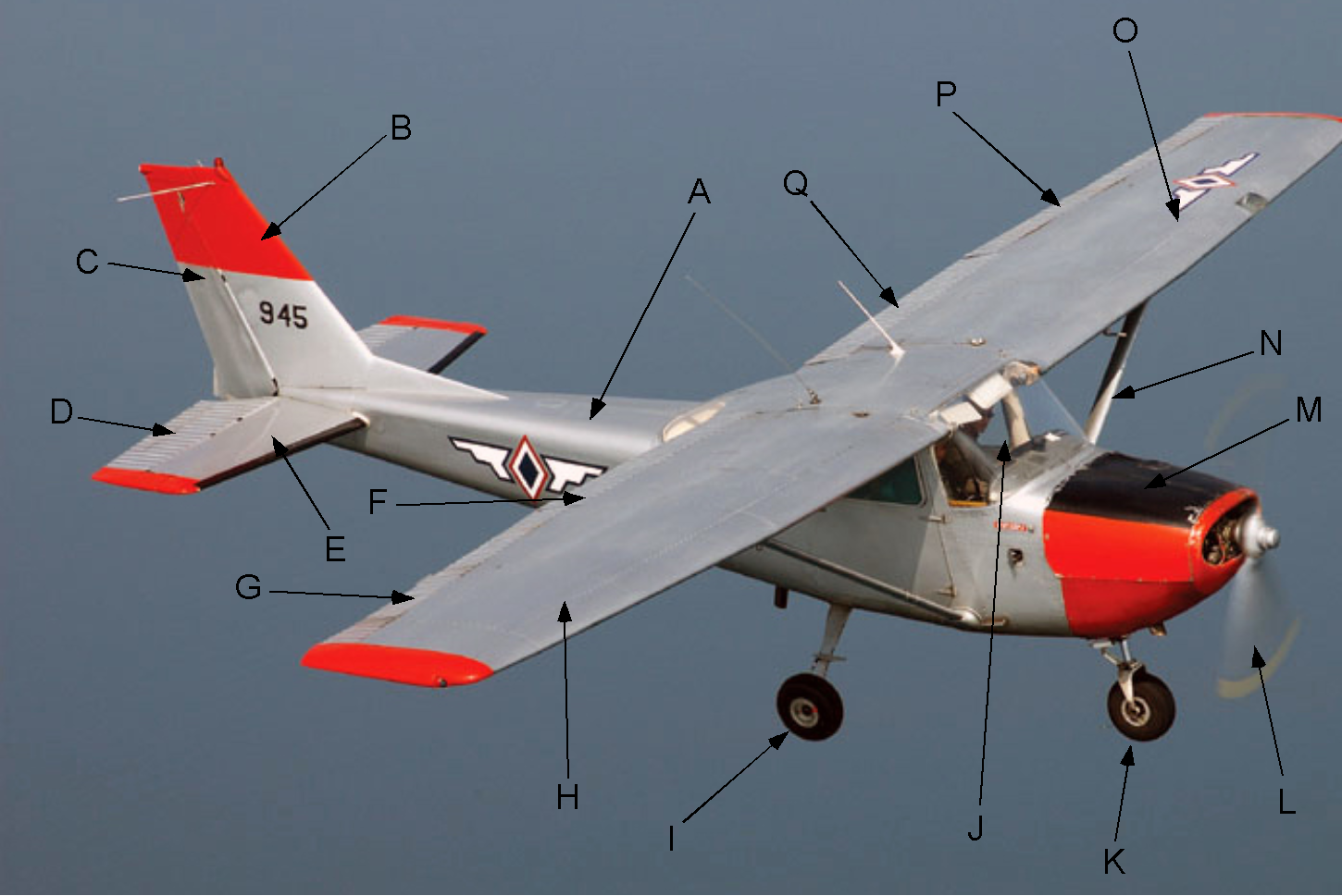
- Wings.
- Vertical stabilizer.
- Fuselage.
- Flaps.
- Undercarriage.
- Propeller.
- Rudder.
- Ailerons.
- Elevator.
- Horizontal stabilizer.
- Wing strut.
- Engine.
- Cockpit.
The aircraft category is “Airplane,” and its class is “Single Engine Land (SEL).”
- Wings. H & O. The wings provide the primary lift force on the airplane to sustain its flight.
- Vertical stabilizer. B. The vertical stabilizer gives the aircraft directional (yaw) stability.
- Fuselage. A. The fuselage is the main body of the aircraft and houses the cockpit, engine, fuel, and various flight systems.
- Flaps. F & Q. The flaps allow the wings to sustain lift at low airspeeds and are used during takeoff and landing.
- Undercarriage. I & K. The undercarriage is the wheels used to maneuver the aircraft on the ground.
- Propeller. L. The propeller provides the propulsive force to move the airplane forward; it is connected to the engine.
- Rudder. C. The rudder is used for directional (yaw) control.
- Ailerons. G & P. The ailerons are differential flaps used for roll control.
- Elevator. D. The elevator is used for pitch control.
- Horizontal stabilizer. E. The horizontal stabilizer gives the aircraft stability in the pitch direction.
- Wing strut. N. The purpose of the wing struts (one for each wing) is to carry tensile loads to resist wing bending from the lift forces.
- Engine. M. The engine provides the power to spin the propeller and create thrust to propel the aircraft forward.
- Cockpit. J. The cockpit is where the pilot(s) sit and where they operate the aircraft. The cockpit will have the flight controls, instruments, radios, and navigation equipment.
Worked Example #2
Based on the image below and using the letters shown in the picture, identify each part of the wing structure and briefly explain its purpose.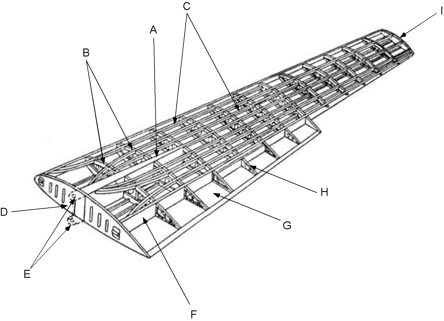
- Main spar.
- Main spar attachments.
- Root rib.
- Tip rib.
- Rear spar.
- Ribs.
- Stringers.
- Flap.
- Flap rib.
- Main spar. A. The main spar will carry the primary bending loads on the wing. The main spar is usually a form of I-beam, which is strong, stiff, and light.
- Main spar attachments. E. The main spar is attached to the fuselage using lugs and bolts. The purpose of the spar attachments is to carry the bending loads through the fuselage from one wing to the other.
- Root rib. D. The root rib is the strongest rib because it carries most of the torsion loads from the wing and transfers them to the fuselage structure.
- Tip rib. I. The tip rib is the last and outermost rib in the wing structure, which, because of the low loads there, can usually be made of the thinnest sheet material.
- Rear spar. F. The rear spar carries some bending loads and attaches to the fuselage to carry torsion loads. The rear spar is also used to attach the flaps and the ailerons.
- Ribs. B. The ribs define the wing’s cross-sectional (airfoil) shape and carry torsional loads. The ribs usually have lightening holes in their webs to reduce weight.
- Stringers. C. The stringers increase the wing bending stiffness to help distribute the loads and prevent skin buckling.
- Flap. G. The flaps are high-lift devices that allow the aircraft to fly at lower airspeeds for takeoff and landing.
- Flap rib. H. The flap rib helps define the flap’s shape and carries torsional loads.
Worked Example #3
What is the International Civil Aviation Organization (ICAO)? What role does the ICAO play in civil aviation?
- The International Civil Aviation Organization, or ICAO, is an agency of the United Nations founded in 1947. It is essential in civil aviation “To ensure international aviation is conducted in a unified, safe, and orderly manner.” The ICAO sets standards and policies regarding international air transport based on “equality of opportunity, and so it is operated soundly and economically for the benefit of all.”
- The ICAO works with the member states and various aviation organizations at all levels to develop International Standards and Recommended Practices (SARPs), which form the basis for all civil aviation regulations worldwide, such as FAA FARs in the US and the EASA standards in Europe. The ICAO does not deal with military aviation, although military aircraft design standards are usually developed by the ICAO SARPs.
Worked Example #4
ICAO Chapter 14 discusses stringent noise limits to regulate aircraft noise emissions and takes effect after December 31, 2020, for all new subsonic jet and propeller-driven aircraft, called Stage 5 by the FAA: https://www.federalregister.gov/documents/2017/10/04/2017-21092/stage-5-airplane-noise-standards. Could you explain why there is such an emphasis today on continuing to reduce aircraft noise?
- In 2013, the ICAO set a new noise standard, known as Chapter 14 or Stage 5, by the FAA. The latest noise standard rules must be met by larger civil aircraft designed and certified for airworthiness after 2017 or smaller aircraft after 2020. The purpose of the new standard is to reduce the noise level for people frequently exposed to aircraft noise, including passengers, flight crews, and the people on the ground, particularly those who live in residential communities surrounding airports.
- According to the ICAO, aircraft noise is considered the most significant cause of adverse community reactions related to airport operation and expansion. This issue persists even though the Stage 4 standard, adopted in 2006, has already reduced the Effective Perceived Noise Level (EPNdB) from the previous noise standards. The new Stage 5 standard requires a cumulative reduction of 7 EPNdB relative to the Stage 4 standard.
- The first aircraft to be certified under the new noise standard was the De Havilland Canada Dash 8-400 turboprop aircraft, which underwent recertification tests to meet the latest noise standards of Chapter 14. According to EASA, about one-third of newer aircraft currently flying have already met the Stage 5 noise standard requirements. However, all new aircraft produced after 2020 will be held to these higher noise standards.
Worked Example #5
The FAA plays a crucial role in commercial space transportation. Do some research on the Internet, and discuss the FAA’s role and what it does regarding regulations that apply to commercial space flight activities.
- You can read about the FAA’s role in commercial space activities here: https://www.faa.gov/space/. The Office of Commercial Space Transportation (FAA/AST) regulates and oversees commercial space launches in the United States.
- The FAA/AST’s mission is to ensure the safety of the public, property, and the national security and foreign policy interests of the United States during commercial launches or re-entry activities. The FAA/AST’s regulatory authority over commercial space transportation is limited to ensuring compliance with the United States’ international obligations, health and safety, property safety, and protecting the public national security and foreign policy interests of the United States.
- The FAA/AST also aims to encourage, facilitate, and promote commercial space launches by the private sector, recommend appropriate changes in federal statutes, treaties, regulations, policies, plans, and procedures, and facilitate the strengthening and expansion of the United States space transportation infrastructure.
Worked Example #6
Refer to the Federal Aviation Regulations (FARs) at https://www.faa.gov/regulations_policies/faa_regulations. Examine Part 23: Airworthiness Standards: Normal, Utility, Acrobatic, and Commuter Airplanes and Part 25: Airworthiness Standards: Transport Category Airplanes. Pick one topic/regulation of your choice from each part, and briefly discuss the nature and scope of this topic/regulation, as well as its significance in establishing the airworthiness of the aircraft.
- Any short discussion on any topic from PART 23 and PART 25 is acceptable. PART 23 considers AIRWORTHINESS STANDARDS: NORMAL CATEGORY AIRPLANES. The contents include standards for flight performance, flight characteristics, controllability, structural design, fire protection, etc.
- Refer to the Federal Aviation Regulations (FARs) at https://www.faa.gov/regulations_policies/faa_regulations. Examine Part 23: Airworthiness Standards: Normal, Utility, Acrobatic, and Commuter Airplanes and Part 25: Airworthiness Standards: Transport Category Airplanes. Pick one topic/regulation of your choice from each part, and briefly discuss the nature and scope of this topic/regulation, as well as its significance in establishing the airworthiness of the aircraft.
- Any short discussion on any topic from PART 23 and PART 25 is acceptable. PART 23 considers AIRWORTHINESS STANDARDS: NORMAL CATEGORY AIRPLANES. The contents include standards for flight performance, flight characteristics, controllability, structural design, fire protection, etc. For example, under “Performance,” we have:
23.2100 Weight and center of gravity.
23.2105 Performance data.
23.2110 Stall speed.
23.2115 Takeoff performance.
23.2120 Climb requirements.
23.2125 Climb information.
23.2130 Landing.
- Using “Takeoff performance” as a further example, we find a discussion on the following: Stall speed safety margins, Minimum control speeds, and climb gradients. Takeoff performance for single-engine and certain low-speed multi-engine airplanes includes determining the ground roll and initial climb distance to 50 feet (15 meters) above the takeoff surface. For certain multi-engine airplanes, takeoff performance consists of a determination of the following distances after a sudden critical loss of thrust, e.g., an aborted takeoff at critical speed, ground roll, and initial climb to 35 feet (11 meters) above the takeoff surface, and takeoff flight path.
- PART 25 considers AIRWORTHINESS STANDARDS: TRANSPORT CATEGORY AIRPLANES. Like Part 23, the contents include standards for flight performance, flight characteristics, controllability, structural design, powerplants, operating limitations, etc. For example, under “Operating Limitations,” we have (in part) the following:
25.1503 Airspeed limitations: general.
25.1505 Maximum operating limit speed.
25.1507 Maneuvering speed.
25.1511 Flap extended speed.
25.1513 Minimum control speed.
25.1515 Landing gear speeds.
- Using “Landing gear speeds” as a further example, we find a discussion of the established landing gear operating speed or speeds, VLO, which they say may not exceed the speed at which it is safe both to extend and to retract the landing gear, as determined under Part 25.729 or by flight characteristics. They go on further to say that for the aircraft, if the extension speed is not the same as the retraction speed (meaning that the maximum safe retraction of the landing gear may not occur at the same airspeed as for the extension of the gear), the two speeds must be designated as VLOEXT and VLORET, respectively. Finally, they conclude by saying that the established landing gear extended speed VLE may be, at most, the speed at which it is safe to fly with the landing gear secured in the fully extended position.
Worked Example #7
The introduction of diverse types of UAVs into the aviation spectrum continues to cause many concerns for regulators at the FAA. Could you discuss some of the reasons? What additional concerns might be associated with drone operations at the ERAU Daytona Beach campus?
- The Federal Aviation Administration (FAA) has established the Federal Aviation Regulations (FARs) to regulate the use of drones, also known as Unmanned Aircraft Systems (UAS), in the National Airspace System (NAS). Part 107 of the FARs pertains specifically to small UAS operations, which includes commercial and non-recreational use of drones weighing less than 55 lb (24.9 kg). The FAA introduced these regulations recently because of the proliferation of various commercially available drones, some of which were being flown high and fast enough to pose a danger to other aviation operations or the general public.
- While the Part 107 rules are flexible to accommodate future technological innovations, they also impose restrictions on the flight operations of all types of drones for safety considerations. FAR Part 107 sets down a series of “common sense” rules requiring the drone operator to avoid all kinds of crewed aircraft and never operate such a drone carelessly or recklessly.
- The specific reasons for the FAA’s concerns regarding the continued introduction of diverse types of drones into the aviation spectrum include the following:
-
- Safety: The FAA’s primary concern is the safety of people and property on the ground and other aircraft in the air. Drones can collide with other aircraft or cause injury or damage.
- Privacy: Using drones has raised privacy concerns, as they can easily fly over private property and capture images and videos. The FAA must balance the privacy rights of individuals with the benefits of drone technology.
- Security: Drones can be used for malicious purposes, such as smuggling, spying, and conducting attacks. The FAA must consider the security implications of drone operations and take measures to prevent unauthorized use.
- Integration: Integrating drones into the NAS is a complex process, and the FAA must ensure that they do not interfere with other aircraft operations or cause air traffic control problems.
- The concern about operating drones near the ERAU campus would be similar to the concerns the FAA has on a larger scale. The top priority would be the safety and security of staff, students, and faculty, as well as avoiding potential interference with aircraft operations at the airport.
Worked Example #8
What might be some of the specific airworthiness concerns that the FAA might be associated with “aging aircraft,” i.e., those flying aircraft 20 to 30 or more years old? Also, look at Part 26 of the FARs – what do these FARs say about older aircraft and their required maintenance?
- The FAA is concerned with the airworthiness of aging aircraft, as these aircraft may experience deterioration of materials, systems, and components over time. To ensure their continued safe operation, the maintenance and inspection requirements for older aircraft may become more frequent and complex.
- Part 26 of the Federal Aviation Regulations (FARs) establishes requirements for the continuing airworthiness of aircraft and related products, parts, and appliances. It covers the maintenance, preventive maintenance, rebuilding, and alteration of aircraft, engines, propellers, and appliances. These FARs specify the inspection and maintenance requirements for aging aircraft, including requirements for repetitive inspections and structural assessments. The requirements for older aircraft may be more stringent than newer aircraft and may include more frequent inspections and particular maintenance tasks.
- Part 26 also outlines the FAA’s policies and procedures for certifying aging aircraft and granting an extension to comply with airworthiness directives. These FARs aim to ensure the safe operation of older aircraft and reduce the risk of in-flight structural failures.
Worked Example #9
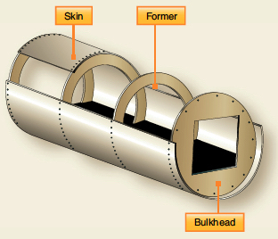
- What kind of structure is shown in the figure below?

- Name two possible materials that could be used for the outer skins.
- Name two possible materials that could be used for the core.
- How is the outer skin material attached to the core material?
- Name two aerospace parts where this type of structure might be used.
- Under what type of loading might this structure fail?
- This image shows a sandwich construction in which a core material is sandwiched between two thin face sheets or skins. Sandwich construction is often used in aerospace structures because it provides high strength and stiffness while minimizing weight. The core material is lightweight and low-density, while the face sheets or skins are more durable and robust. Combining these materials creates a composite structure with superior strength, stiffness, and durability compared to each material separately.
- The skins (face sheets) can be made of fiberglass, carbon fiber, or aluminum, depending on the specific application and performance requirements.
- Some typical materials used for the core in sandwich construction for aerospace applications include foams, paper or aluminum honeycomb, or even balsa wood.
- The skins (face sheets) are attached to the core by bonding with various adhesives. A layer of glue can be applied to the surface of the core material, and the skin material is then placed on top of it. The adhesive is then cured, forming a solid bond between the two materials. When using composite materials for the skins, the core material and a resin that holds the two materials together will be cured under pressure to compress the outer skin material and the core material.
- Sandwich panels are used to construct aircraft flight control surfaces, nose cones, undercarriage doors, and cabin floors. etc., to provide high strength and stiffness while keeping the weight low. They may also be used to construct spacecraft structures, such as payload fairings, which protect the payload from the aerodynamic loads during the launch. Sandwich structures are also used extensively in the manufacture of helicopter rotor blades.
- Sandwich structures can fail for various reasons, including overloading, buckling of the skins, poor bonding, which causes skin delamination, impact damage that causes crushing of the face and the core, fatigue under excessive cyclic loading, and environmental degradation (especially with foams). Proper design, materials selection, and maintenance can help prevent these failure modes and ensure the structural integrity of sandwich structures.
Worked Example #10
- What kind of structure is shown in the figure below?
- What behavior is a primary concern with this type of structure?
- Under what types of loading might this structure show evidence of pending failure?
- What changes to this structure could be made to help prevent this failure?
- Name two aerospace parts where this structure might be used.
- This image shows a monocoque or shell structure. A monocoque structure is a design in which the outer skin or shell provides most of the structural strength and stiffness without needing internal framing or bracing. In a monocoque structure, loads are distributed through the skin, which is usually made of a strong and thicker material to carry the required loads. This approach can result in a lighter and more streamlined structure because it eliminates the need for internal structures or fasteners such as rivets.
- Monocoque structures are designed to be lightweight and strong but can be vulnerable to buckling. Buckling can occur when compressive forces cause the skin to deform (inward or outward), causing the shell structure to wrinkle and lose its rigidity and strength.
- Buckling usually happens when a monocoque structure is subjected to excessive compressive, torsion, or bending loads. The primary consideration is typically any part of the structure under compressive loads.
- Various techniques can be used to prevent buckling in a monocoque structure, such as adding stiffeners, ribs, or stringers to the internal structure. Increasing the thickness of the skin or changing its material are other options.
- A monocoque structure is commonly used in aircraft and spacecraft where weight is critical. Monocoque structures on an aircraft can be found in fuselages and lightly loaded parts such as control surfaces and trim tabs. The crew module or capsule on a spacecraft is usually a monocoque structure and may be made of sandwich construction. The payload fairing on a rocket is generally designed as a monocoque structure, with the skin and internal structure providing the required strength and stiffness.
Worked Example #11
What type of aircraft fuselage structure is shown in the photograph below? Discuss the advantages/disadvantages of this type of construction relative to the monocoque and semi-monocoque types of structural design.
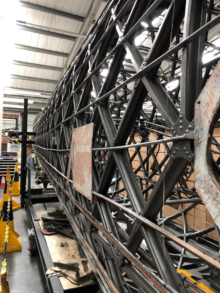
- This photograph shows a geodetic (sometimes called geodesic) airframe. It is a lattice or “basket-weave” construction type with tremendous strength. Although it is a rare type of construction, it has been used for some dirigibles. British aeronautical engineer Barnes Wallis popularized it in the 1930s and 1940s for several aircraft, including the Wellington bomber (as in this photo), a very successful British aircraft during WW2.
- The structure needs to be covered with doped fabric because if an aluminum skin is riveted to the underlying structure, it makes the aircraft too heavy. This structure is relatively time-consuming and expensive to build (it has many parts) and is difficult to repair. In addition, using a fabric skin means it is not so durable in service; the fabric is easily damaged and must be replaced every few years because it deteriorates when exposed to the weather. However, the geodetic structure has much redundancy in load-carrying in the event of battle damage, an outcome verified during WW2. This type of construction has also been used for some spacecraft, such as payload fairings.
Worked Example #12
Discuss how introducing digital “fly-by-wire” flight control systems on modern aircraft has reduced pilot workload and improved flight safety. What is “care-free” handling, and why is this feature necessary for a military fighter aircraft?
- The introduction of digital “fly-by-wire” (FBW) flight control systems in modern aircraft has significantly reduced pilot workload and improved flight safety. In an FBW system, the pilot’s control inputs are transmitted electronically to the aircraft’s control surfaces rather than mechanically through cables and pushrods, as in traditional mechanical systems.
- One critical benefit of FBW systems is that they can automatically compensate for environmental factors, such as turbulence and wind, reducing the pilot’s workload. FBW systems can also automatically enforce flight envelope limitations and prevent the aircraft from exceeding performance limits, reducing the risk of pilot error. Additionally, FBW systems can integrate multiple redundant control channels, providing increased safety in a failure.
- “Care-free” handling is a feature in some FBW military fighter aircraft that allows the aircraft to automatically maintain stability and control during high-performance maneuvers, even if the pilot’s control inputs are incorrect. This feature is essential because it can significantly improve the pilot’s ability to engage in aerial combat while reducing the risks of losing control or structurally overstressing the airframe.
Worked Example #13 – Finding the strained length of a component
If a structural component in an airframe has a measured strain  of 0.0025 and an original length
  of 1,000.0 mm, find the strained length of the component.
Strain is defined as
![\[ \epsilon = \frac{\Delta L}{L} \]](https://eaglepubs.erau.edu/app/uploads/quicklatex/quicklatex.com-25b227817b20a66bd53c926da60b74e4_l3.svg "Rendered by QuickLaTeX.com")
and rearranging gives
![\[ \Delta L = \epsilon L \]](https://eaglepubs.erau.edu/app/uploads/quicklatex/quicklatex.com-05ee6520e807043f4aeb6fe46f9b9bf6_l3.svg "Rendered by QuickLaTeX.com")
Inserting the known values for this problem gives
![\[ \Delta L = \epsilon L = 0.0025 \times 1,000.0 \times 10^{3} = 0.0025~\mbox{m} = 2.5~\mbox{mm} \]](https://eaglepubs.erau.edu/app/uploads/quicklatex/quicklatex.com-d5c0f6ecbd8441b1df7028dea7b7340c_l3.svg "Rendered by QuickLaTeX.com")
Therefore, the strained length of the member will be
![\[ L + \Delta L = 1,000 + 2.5 = 1,002.5~\mbox{mm} \]](https://eaglepubs.erau.edu/app/uploads/quicklatex/quicklatex.com-dfb611a6ba3cbf452b2a8bc95c4b61ad_l3.svg "Rendered by QuickLaTeX.com")
