51 Supersonic & Hypersonic Flight
Introduction
Engineers have always strived to develop flight vehicles that can fly fast and still faster. While a modern military will always have a “need for speed” for many of their missions, the ability of civil aircraft to quickly transport passengers and cargo from point to point with low costs has never been more acute. Aircraft are not intrinsically limited to subsonic or transonic flight speeds, but for them to fly supersonically requires the consideration of several other factors, not just limited to their aerodynamics and propulsion system. In supersonic flight conditions, kinetic heating of the airframe is also a significant consideration, posing new challenges in designing aircraft structures and developing construction materials suitable for supersonic flight.
After the aerodynamics, stability and control, and propulsion issues of flight near and beyond Mach 1.0 were beginning to be understood by the early 1950s, it was only a short time before new military airplane designs routinely flew supersonically. The invention of the turbojet engine and the afterburner, the latter in which extra fuel is burned in the exhaust stream, increased thrust significantly and allowed airplanes to accelerate through Mach 1 and maintain supersonic flight. Many different types of military supersonic airplanes were developed in the 1950s and onward, including those with delta wings and wings with variable-sweep geometries.
However, civil supersonic airplanes carrying fare-paying passengers are in a different class. The rise and fall of the Anglo-French Concorde and the Soviet Tupolev Tu-144 provide compelling case studies on the intersection of technological capabilities and commercial viability. While the Concorde was a remarkable engineering achievement, its economic viability was limited, as Boeing discovered with their proposed Model 2707 SST. Furthermore, Concorde’s loud sonic booms restricted its flights to overwater routes and, hence, its economic potential, which led to the eventual discontinuation of all supersonic passenger travel in 2003. It seems unlikely that supersonic transport airplanes (SST) will return to the skies anytime soon, even if they are shown to be technically feasible. Any revival of supersonic passenger travel will require a comprehensive and strategic approach that considers the technical aspects of designing long-range supersonic airplanes, in conjunction with economic, environmental, and regulatory matters. In this regard, new companies like Boom Supersonic have much to be concerned about.
Learning Objectives
- Become familiar with the design features of supersonic airplanes and why such airplanes should have thin, highly swept, or delta-type wings.
- Better understand the effects of Mach number on the formation of shock waves and the aerodynamic efficiency of wings in supersonic flight.
- Know how to calculate the aerodynamic coefficients on supersonic airfoils and wings.
- Understand the principle of vortex lift creation on slender delta wings at high angles of attack.
- Appreciate some of the challenges in the engineering and operations of a supersonic transport airplane (SST).
- Understand the additional technical challenges for aircraft flying at hypersonic speeds.
- Know how to calculate aerodynamic coefficients on bodies in hypersonic flow.
History
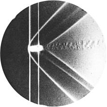
In 1887, Ernst Mach and Peter Salcher presented their paper on the supersonic motion of a projectile “Photographische Fixirung der durch Projectile in der Luft eingeleiteten Vorgänge,” in the journal Sitzungsberichte der Kaiserlichen Akademie der Wissenschaften [Wien], Mathematisch-Naturwissenschaftliche,” one of their famous schlieren photos being shown below. They deduced theoretically and then verified experimentally the existence of a conical shock wave (now called a Mach cone or Mach wave) that would form at the nose of the projectile (or any other object) that flies supersonically.
In the early 1920s, Alexander Martin Lippisch proposed a series of delta-wing concepts, although not for supersonic airplanes but for unconventional “tailless” airplanes. However, by 1930, there was much interest in supersonic flight, and the aerodynamics associated with supersonic flows were being studied extensively in wind tunnels, with parallel theoretical studies underway. Jakob Ackeret published a pioneering paper on the lift and drag of a supersonic airfoil in 1925 titled “Luftkräfte auf Flügel, die mit größerer als Schallgeschwindigkeit bewegt werden” in the journal Zeitschrift für Flugtechnik und Motorluftschiffahrt.
During WW2, airplane designs were driven by the need for faster airplanes like the P-51 Mustang, Spitfire, and others, which could approach the speed of sound in a dive. However, the increased speeds presented a new problem: a strong nose-down pitching moment, where the airplane’s nose would suddenly pitch downward uncontrollably. This phenomenon was known as the “dive recovery problem” or “Mach tuck,” which sometimes made a recovery from the dive impossible. One solution was using dive recovery flaps or airbrakes designed to disrupt the airflow over the wings and tail surfaces, reducing the nose-down pitching tendency during high-speed dives. Additionally, advancements in aerodynamic research and understanding the physics of supersonic flight led to the development of new airplane designs, such as swept-wing configurations, ultimately allowing airplanes to operate at higher airspeeds before encountering Mach tuck and other adverse effects resulting from the compressibility of the airflow.
The aerodynamic effects of using sweep at high speeds were first investigated in Germany as early as 1935 by Albert Betz and Adolph Busemann. After that, Lippisch designed the famous rocket-powered Messerschmitt Me 163 Komet, which had a swept, almost delta wing and was powered by a rocket engine. It was the first piloted airplane of any type to approach Mach 0.9 but not exceed the speed of sound in level flight. This airplane was followed by the Messerschmitt Me 262, which had a swept wing and was the world’s first operational turbojet-powered fighter airplane.
The first airplane to fly supersonically in straight and level flight was the U.S.’s Bell X-1, a rocket-powered research airplane, which performed several test flights near the speed of sound in the late 1940s. The air-dropped Bell X-1, piloted by Chuck Yeager, first reached supersonic speeds in level flight in October 1947. The British were also working on supersonic airplanes. The Miles M.52 was designed in secrecy during WW2 between 1942 and 1945, with Frank Whittle‘s Power Jets being contracted to produce its turbojet engine. The M.52 design had a conical bullet-shaped nose, thin, mildly swept wings, and a tail with sharp leading edges. While this airplane never flew with a pilot, scaled models were flown supersonically in 1947.
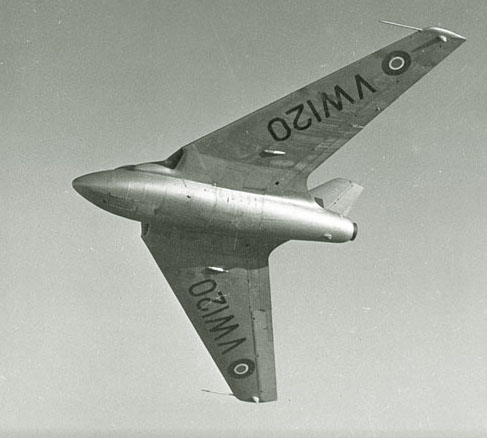
In September 1948, the tailless swept-wing de Havilland D.H.108 Swallow, as shown in the photograph below, reached just over Mach 1.0 while in a shallow dive. Unfortunately, the airplane killed its designer and pilot, Geoffrey de Havilland Jr., because of high unsteady aerodynamic-induced loads caused by shock-induced flow separation and stall, resulting in a catastrophic structural failure and an in-flight breakup of the airplane. The U.S. continued further work on supersonic flight with variants of the X-1 (A through E models), the X-1E exceeding Mach 2 in September 1956.
Supersonic Airfoil Characteristics
The physics of the flows of airfoils and wings at supersonic flight conditions are significantly different from those obtained in subsonic flight, which is the reason the value of the Mach number is so crucial in classifying aerodynamic flows. In supersonic flight, the formation of shock waves and expansion waves significantly impact the performance of the wing or airfoil. For example, on the one hand, shock waves cause drag and increase the pressure on the wing’s surface. On the other hand, expansion waves arise when a supersonic flow is turned away from itself, reducing the pressure on the wing’s surface and creating lift. Therefore, the physics of these compressibility effects must all be carefully considered when designing airfoils and wings suitable for airplanes capable of supersonic flight.
Supersonic Airfoil Shapes
The figure below shows that a supersonic airfoil or wing typically features a sharp leading edge and relatively flat upper and lower surfaces to minimize wave drag and maximize lift production. The airfoil’s maximum thickness is critical in determining airfoil performance at supersonic speeds. The best supersonic airfoil designs are thin (i.e., low thickness-to-chord ratios) and mildly cambered airfoils with specific thickness distributions and curvature to manage shock waves and regions of flow expansions. These designs focus on minimizing wave drag and optimizing the achievable lift-to-drag ratios. A diamond-wedge airfoil is a specific type of airfoil shape used in certain supersonic flight applications.
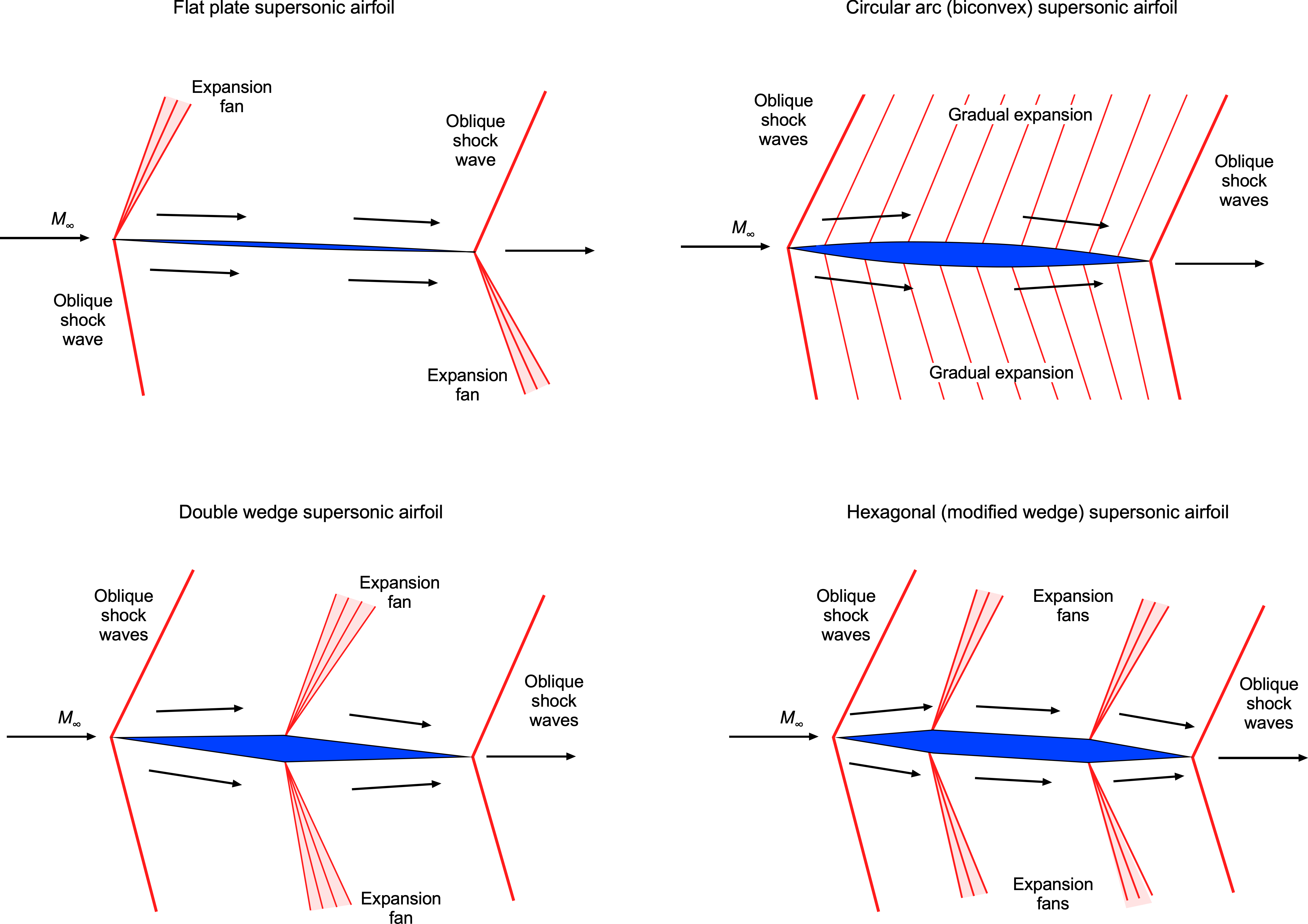
One of the key advantages of the diamond-wedge airfoil is its ability to maintain good lift-to-drag ratios over a broader range of angles of attack. They are often used for control surfaces on missiles. However, they are rarely used on the main wings of actual supersonic airplanes because of their abysmal performance at low Mach numbers and high angles of attack, such as during takeoff and landing. Therefore, supersonic airplanes are more likely to use thin, semi-circular arc sections, with the addition of high-lift devices for low-speed flight.
Flow Patterns & Pressure Distributions
Consider the flow about an airfoil in the form of a double-wedge or diamond shape experiencing a supersonic flow, as shown in the figure below. Notice that in a supersonic flow, the flow upstream gets no warning of the approaching airfoil, so the streamlines have no curvature. Oblique compression shock waves occur at the leading edge of the airfoil. The Mach number across the shocks decreases (but remains supersonic), and the static pressure increases over the free-stream value. Notice in the figure below the more significant pressure increase on the lower surface, contributing significantly to the lift.
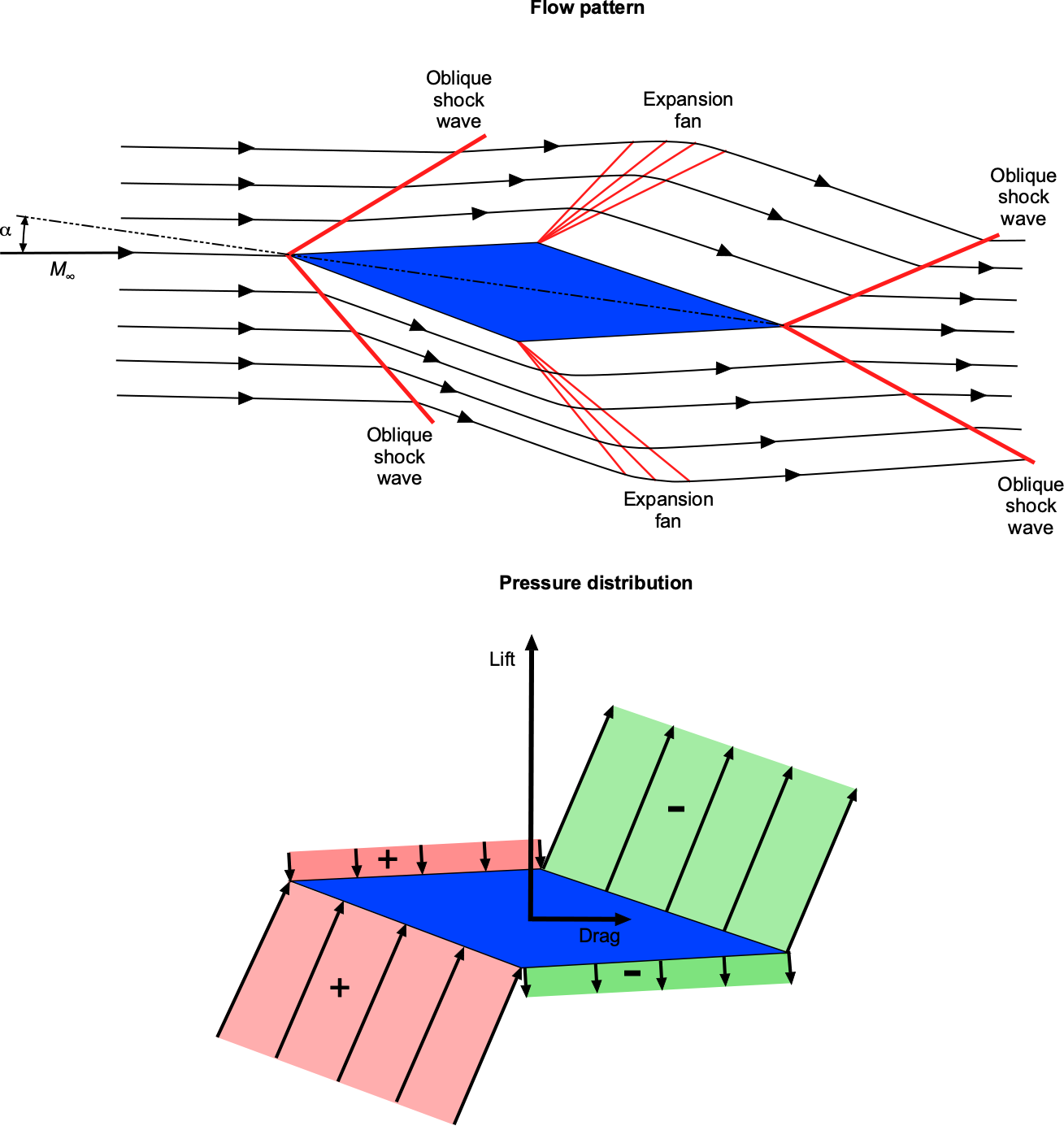
At the points of maximum airfoil thickness, expansion waves appear, which causes the Mach number to increase and the pressure to decrease after the expansion is complete. The upper surface of the airfoil now contributes to lift production. Rarefaction shock waves form at the trailing edge, increasing the Mach number and returning the pressure to the free-stream value. This pressure distribution explains why the center of lift (center of pressure) is located at or near the mid-chord of a supersonic airfoil.
Lift & Drag Characteristics
For a thin airfoil in incompressible flow (i.e., linearized thin airfoil theory below stall), the relationship between the lift coefficient,  , and angle of attack,
  , is given by
(1) 
where the lift-curve slope,  , is equal to
  per radian of angle of attack. For linearized subsonic flow, the relationship changes to
(2) 
where  is known as the Glauert factor. Therefore, it is apparent from Eq. 2 that the lift-curve slope continuously increases in subsonic flow with increasing Mach number. Hover, notice that this result becomes singular as
  approaches one, which is one limitation of the linear theory.
For linearized supersonic flow, the between the lift coefficient and angle of attack is given by
(3) 
This result shows that the lift-curve slope is lower in supersonic flight and decreases with increasing Mach number.
The results in Eq. 1 and 3 are considered classical solutions in the airfoil theory, and allow the determination of the lift coefficients on airfoils at small angles of attack. These thin airfoil approximations agree well with measurements made on thin two-dimensional airfoils, as shown in the figure below. They also have good validity when extended to three-dimensional flow, such as when predicting the lift-curve slope of a finite wing, particularly where the sections behave in a two-dimensional fashion. However, for supersonic wings, the regions influenced by subsonic versus supersonic flow still need to be considered.
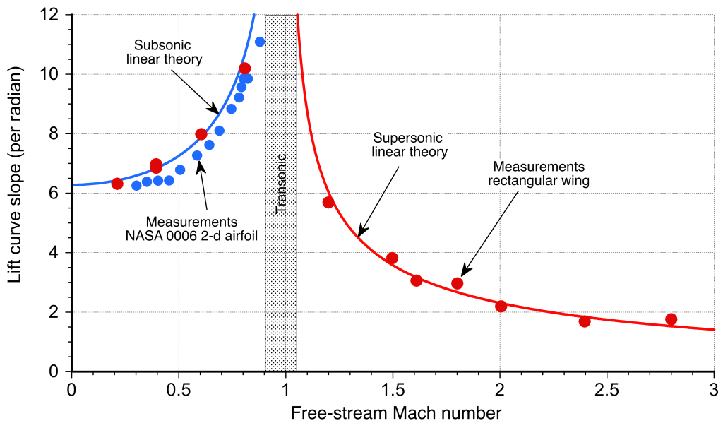
The linearized supersonic airfoil theory shows that the lift coefficient is independent of the airfoil shape. Indeed, the lift coefficient produced by a supersonic airfoil at a given angle of attack is the same for a flat plate, a diamond-wedge airfoil, or a biconvex airfoil. The drag, however, is different because the dominant source of drag is wave drag, which depends strongly on the details of the airfoil shape.
For a flat plate airfoil, the wave drag coefficient,  , is
, is
(4) 
and for a diamond-wedge airfoil with a half angle,  , then
(5) 
If the chord of the airfoil is  , with a maximum thickness
  at mid-chord (i.e., at
  , then from the geometry of the wedge then
(6) 
Therefore, Eq. 5 can be written as
(7) 
which shows that wave drag increases with the square of the airfoil thickness. The wave drag of a biconvex airfoil with small concavity (i.e., a large radius of curvature) is
(8) 
In general, the wave drag of a supersonic airfoil can be expressed as
(9) 
where  is its maximum thickness-to-chord ratio and
  is its maximum camber. The values of the constants
  and
and  will depend on the exact shape of the airfoil.
Nevertheless, regardless of the shape, one of the most interesting and important characteristics of an airfoil operating in supersonic flow is that its wave drag is proportional to the square of its thickness-to-chord ratio and the square of its camber. Therefore, it becomes clear why the airfoils used on the wings of supersonic airplanes must be very thin and mildly cambered compared to those used on subsonic airplanes.
Check Your Understanding #1 – Lift-to-drag ratio of a supersonic airfoil.
At what angle of attack is the maximum lift-to-drag ratio obtained for a diamond-wedge supersonic airfoil with a wedge half angle ?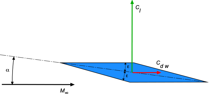
Show solution/hide solution.
The lift coefficient for a diamond-wedge airfoil is given by
![\[ C_l = \frac{4}{\sqrt{M_{\infty}^2 - 1}} \, \alpha \]](https://eaglepubs.erau.edu/app/uploads/quicklatex/quicklatex.com-bef92b5b54c5b546269097556c5cd1de_l3.svg "Rendered by QuickLaTeX.com")
and the wave drag coefficient by
![\[ C_{d_{w}} = \frac{4 \left( \alpha^2 + \epsilon^2 \right) }{\sqrt{M_{\infty}^2 - 1}} \]](https://eaglepubs.erau.edu/app/uploads/quicklatex/quicklatex.com-29d4a010ca8eb02f61fac7bbd0299537_l3.svg "Rendered by QuickLaTeX.com")
Therefore, the lift-to-drag ratio is
![\[ \frac{C_l}{C_{d_{w}}} = \frac{\alpha}{(\alpha^2 + \epsilon^2)} \]](https://eaglepubs.erau.edu/app/uploads/quicklatex/quicklatex.com-ef6ad7b5c050ec6573a64c04d6a1e79d_l3.svg "Rendered by QuickLaTeX.com")
Differentiation with respect to gives
![\[ \frac{d (C_l/C_{d_{w}})}{d \alpha} = \frac{\epsilon^2 - \alpha^2}{(\alpha^2 + \epsilon^2)^2} \]](https://eaglepubs.erau.edu/app/uploads/quicklatex/quicklatex.com-f95e1c6840fe8881d46954d75cd7f3ea_l3.svg "Rendered by QuickLaTeX.com")
which must be equal to zero for a maximum or minimum, i.e.,
![\[ \frac{\epsilon^2 - \alpha^2}{(\alpha^2 + \epsilon^2)^2} = 0 \]](https://eaglepubs.erau.edu/app/uploads/quicklatex/quicklatex.com-feb26432bd5014ea61f682760d802988_l3.svg "Rendered by QuickLaTeX.com")
Therefore, the result is  . Substituting back gives the maximum lift-to-drag ratio as
![\[ \left. \frac{C_l}{C_d} \right\rvert_{\rm max} = \frac{1}{2 \epsilon}~\mbox{~at $\alpha = \epsilon$} \]](https://eaglepubs.erau.edu/app/uploads/quicklatex/quicklatex.com-8e7f909a233b1d408791ae18d67ad45f_l3.svg "Rendered by QuickLaTeX.com")
Pitching Moments
Another interesting characteristic of a supersonic airfoil (or wing) is that its aerodynamic center of pressure approaches the mid-chord location. In contrast, a subsonic airfoil is closer to the quarter-chord. The center of pressure location for a supersonic airfoil can be expressed as
(10) 
which is independent of the Mach number. The actual location depends on the camber and angle of attack but quickly approaches mid-chord for even low angles. Note: All angles are expressed in radians. For a flat plate airfoil, the center of pressure is exactly at mid-chord.
The practical upshot of this means that a wing (or airplane) that transitions from subsonic to supersonic flight has a significant aft movement of its aerodynamic center. As shown in the figure below, this effect can produce a sizeable nose-down pitching moment about the airplane’s center of gravity. This fundamental change in aerodynamics has severe implications for the longitudinal pitch stability of a supersonic airplane as it transitions from and to subsonic flight conditions. Indeed, this is the physical explanation of the “Mach tuck” phenomenon noticed on early airplanes as they began to approach the speed of sound.
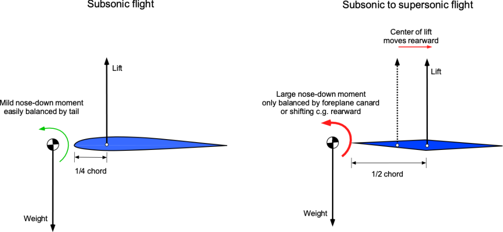
Today, designers can balance out these moments using aerodynamic forces, such as from a foreplane canard on some supersonic fighter airplanes or by pumping a specific weight of fuel to the trim tanks further aft inside the wings to gain the proper location of the center of gravity, such as was done with the fuel system on Concorde.
Check Your Understanding #2 – Calculation of the lift-to-drag ratio of a supersonic airfoil.
A supersonic double-wedge airfoil with a thickness-to-chord ratio of 10% is operated at an angle of attack of 5.5 degrees at a Mach number of 2.5. For these conditions, calculate the lift and drag coefficients, lift-to-drag ratio, and the moment coefficient about the leading edge.
Show solution/hide solution.
In this case, the values given lead to
![\[ \sqrt{M_{\infty}^2 - 1} = \sqrt{2.5^2 - 1} = 2.291 \]](https://eaglepubs.erau.edu/app/uploads/quicklatex/quicklatex.com-e914593adaff56d08ca05d6fcfff75e6_l3.svg "Rendered by QuickLaTeX.com")
and
![\[ \alpha = 5.5 \times \frac{\pi}{180} = 0.096~\mbox{rads} \]](https://eaglepubs.erau.edu/app/uploads/quicklatex/quicklatex.com-2b8bb45fa8c7a443ccdbefcf9cd43feb_l3.svg "Rendered by QuickLaTeX.com")
The lift coefficient is
![\[ C_l = \frac{4 \, \alpha }{\sqrt{M_{\infty}^2 - 1}} = \frac{ 4 \times 0.096}{2.291} = 0.168 \]](https://eaglepubs.erau.edu/app/uploads/quicklatex/quicklatex.com-9b8d60bdd6ef58e069a5e626ea926dc4_l3.svg "Rendered by QuickLaTeX.com")
The wave drag coefficient is
![\[ C_{d_{w}} = \frac{4}{\sqrt{M_{\infty}^2 - 1}} \bigg( \alpha^2 + \left( \frac{t}{c} \right)^2 \bigg) = \frac{4.0}{2.291} \left( 0.096^2 + 0.1^2 \right) = 0.0336 \]](https://eaglepubs.erau.edu/app/uploads/quicklatex/quicklatex.com-085d3059cac4c9043245f48604f51846_l3.svg "Rendered by QuickLaTeX.com")
Therefore, the lift-to-drag ratio is
![\[ \frac{C_l}{C_{d_{w}} } = \frac{0.168}{0.0336} = 5.0 \]](https://eaglepubs.erau.edu/app/uploads/quicklatex/quicklatex.com-1c80d770111ee417c072c9dd694259d6_l3.svg "Rendered by QuickLaTeX.com")
The pitching moment coefficient about the leading edge will be
![\[ C_{m_{\rm le}} = -\frac{x_{\rm cp}}{c} \, C_l = -0.5 \times 0.168 = -0.085 \]](https://eaglepubs.erau.edu/app/uploads/quicklatex/quicklatex.com-d4fb21c1aeb101274f65dcdcc7ef8611_l3.svg "Rendered by QuickLaTeX.com")
the minus sign denoting a nose-down moment.
Supersonic Wings
Interest in the theory and practice of supersonic flight continued at various research centers such as the NACA, with wind tunnel tests confirming the development of the high drag on an airplane in supersonic flight, which had been known as the “sound barrier.” Although Mach 1 is not a barrier per se, these conditions result in significant changes in the flow physics of the airplanes that can affect their flight performance, stability, and control characteristics.
After the work of Betz and Busemann before WW2, Robert T. Jones at NACA Langley was the first to develop an aerodynamic theory for supersonic delta wings, his work “Wing Plan Forms for High-Speed Flight” being published as NACA TR-863 in 1947. His approach combined the theory of thin supersonic airfoils with highly swept delta wings. This wing design became the basis for the first generation of supersonic delta-wing airplanes. Subsequently, several different supersonic airplane prototypes were built and flown by American and British manufacturers. However, such airplanes did not always have good handling qualities and required high landing speeds. As a result, there were many mishaps with the first generation of supersonic airplanes, including stall/spin events and other departures from controlled flight, often resulting in fatalities. In this regard, the Lockheed F-104 Starfighter became one of the most notorious among other jet fighter airplanes.
Mach Angle
As an airplane flies faster and approaches Mach 1, pressure disturbances produced by the airplane begin to merge, and a strong compression wave forms in front of the airplane. As the airplane becomes supersonic, this wave becomes a single wavefront called a shock wave. In three dimensions, this shock wave is called a Mach cone, which extends back from the nose of the airplane, as shown in the schematic below.
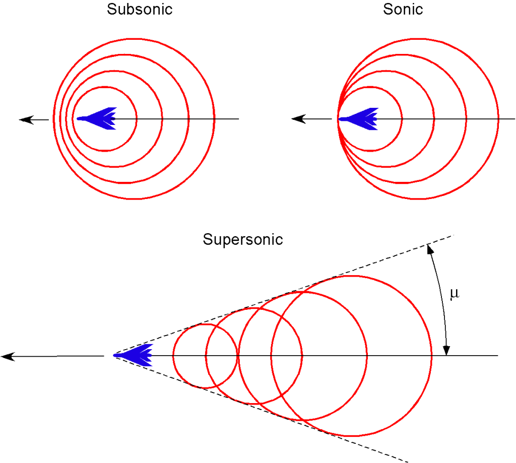
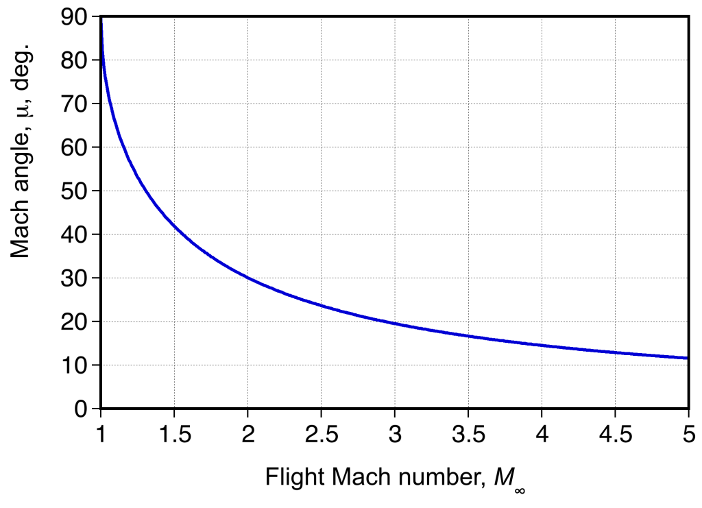
The figure below shows schlieren flow visualization images about a model of a fighter airplane in a supersonic wind tunnel. Notice the build-up in the number and intensity of the almost normal shock waves as Mach 1 is approached. In supersonic flight, the Mach cone becomes increasingly swept back with increasing flight Mach numbers. The angle  is used to denote the Mach angle, as given by
(11) 
which is the half apex angle of the Mach cone.

Therefore, the Mach angle is 90 at
at  , and its value decreases quickly beyond Mach 1, as shown in the figure below. Notice that even by a Mach number of 2, the Mach cone is already swept back 60 to a half apex angle of
  . For hypersonic speeds, the Mach angle is so steep that it can touch the body’s surface, so a blunt or bluff body shape is often a better design solution to keep the shock waves away from the surface.
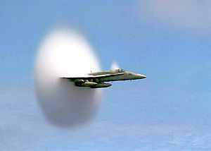
In the figure below, the signature of the shock waves and Mach cone can also be seen through the natural condensation of water vapor in the air in the lower pressure and slightly lower temperature regions produced over the airplane. In this case, only the signature of the expansion shock is produced, and the compression shock increases the air temperature. This effect only occurs with humid air conditions, and the lighting conditions must also be suitable to capture such an image.
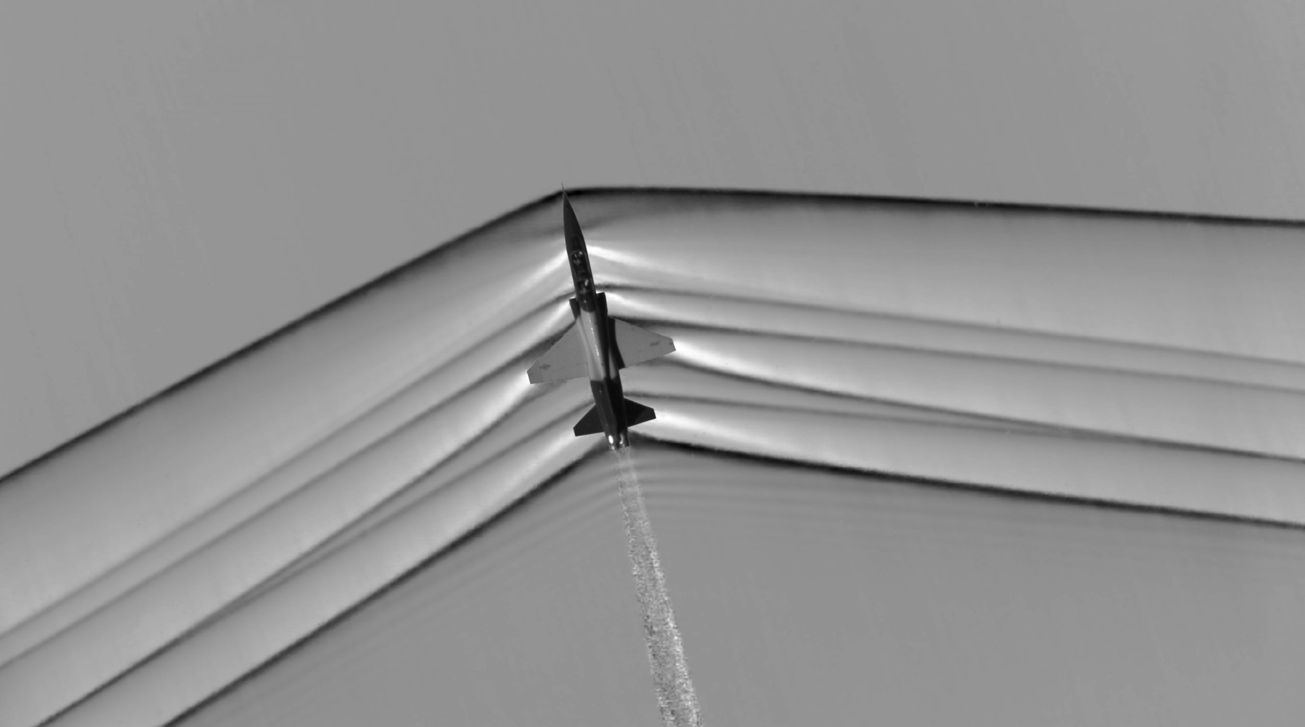
The photograph below is a fascinating schlieren image of the plethora of Mach (shock) waves generated by an actual airplane during supersonic flight. The optical method for visualizing this flow is called Airborne Background Oriented Schlieren (ABOS), the light source is the sun, and the image is taken from a chase airplane. Notice the particularly strong (i.e., darker looking) Mach waves at the nose and tail of the airplane, which are those responsible for the sonic booms heard on the ground. Also apparent in this image is the turbulence from the engine exhaust.
Check Your Understanding #3 – Mach Number of an airplane from the shock wave angle
The half-angle of the conical shock wave formed by a supersonic jet fighter is 25 degrees. What is the flight Mach number of the airplane? What is the airplane’s true airspeed if the local air temperature is -20oC?
Show solution/hide solution.
The half apex angle of the Mach cone angle, , is given by
![\[ \mu = \sin^{-1} \left( \frac{1}{M_{\infty}} \right) \]](https://eaglepubs.erau.edu/app/uploads/quicklatex/quicklatex.com-8d99a3b477d9790354303c8e9b178c07_l3.svg "Rendered by QuickLaTeX.com")
Therefore,
![\[ M_{\infty} = \frac{1}{\sin \mu} = \frac{1}{\sin 25^{\circ}} = 2.36 \]](https://eaglepubs.erau.edu/app/uploads/quicklatex/quicklatex.com-9daf97a5b6e59a66a87d54a78e1460ca_l3.svg "Rendered by QuickLaTeX.com")
The absolute temperature,  , is -20 + 273.15 = 253.15K, so the speed of sound is
![\[ a_{\infty} = \sqrt{\gamma \, R \, T_{\infty} } = \sqrt{ 1.4 \times 287.057 \times 253.15} = 318.96~\mbox{m/s} \]](https://eaglepubs.erau.edu/app/uploads/quicklatex/quicklatex.com-2dba9e4a62e19cf0591dedff5a117908_l3.svg "Rendered by QuickLaTeX.com")
Therefore, the true airspeed of the jet airplane is
![\[ V_{\infty} = a_{\infty} M_{\infty} = 318.96 \times 2.36 = 752.75~\mbox{m/s} \]](https://eaglepubs.erau.edu/app/uploads/quicklatex/quicklatex.com-07b5fb3174cbff9c0c9362faddb6468b_l3.svg "Rendered by QuickLaTeX.com")
Wing Sweep
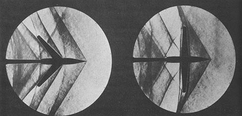
The Mach angle is essential in supersonic wing design because pressure disturbances in a supersonic flow are confined to the cone region as determined by the Mach angle. Unlike a subsonic flow, there is no upstream influence beyond the Mach cone in a supersonic flow; pressure disturbances are only transmitted along the length of the Mach cone and downstream. The consequence of this fact is important because if the wing’s leading edge is swept back behind the Mach cone, then the wing experiences relatively lower drag (i.e., low wave drag), as shown in the schlieren images below. Otherwise, if the shock wave reaches the wing, the effects of the shock will cause disruptions to the flow in the boundary layer, increasing drag and perhaps even producing flow separation.
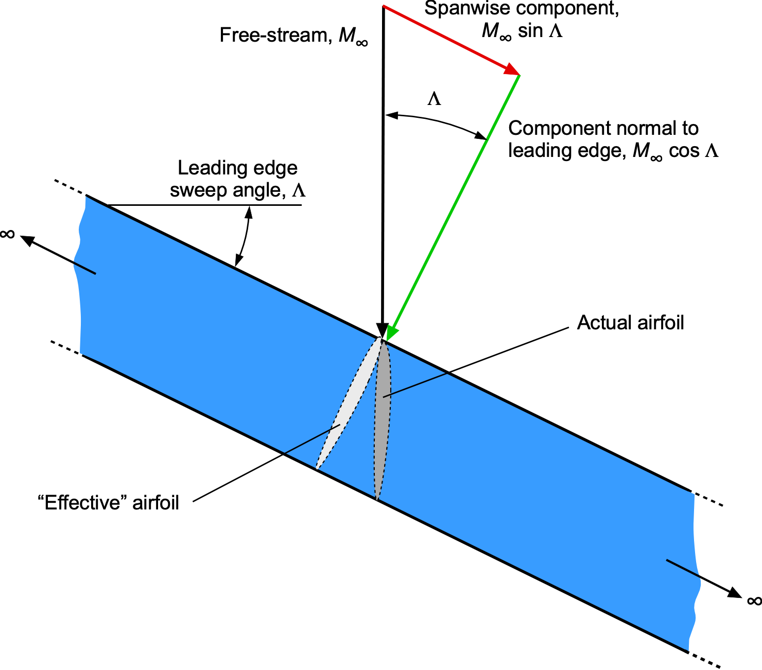
Consider a thin wing of infinite span, as shown in the figure below. The wing’s leading edge is swept back at an angle  between the free-stream Mach number and the component of the Mach number normal to the leading edge. The normal component,
  , affects the wing’s chordwise pressures and aerodynamic loading; the spanwise component
  has no effect on the flow developments over the wing. This result is called the independence principle of sweep, or simply the independence principle, after Adolf Busemann. Notice also that the “effective” airfoil shape affected by the flow has a longer chord and a lower thickness-to-chord ratio, thereby increasing the critical Mach number.
Consider the figure below, which shows a two-dimensional section of a wing with subsonic and supersonic flows. If the component is less than unity, then the chordwise pressures and wing loadings will be the same as those produced on an unswept wing in a free-stream Mach number of , i.e., in a subsonic free-stream. Point Q will be inside the Mach cone from all points such as P, and the flow about the wing will be subsonic, which is called a subsonic leading edge, i.e.,
(12) 
which means
(13) 
so  . The wave drag, therefore, will be zero.
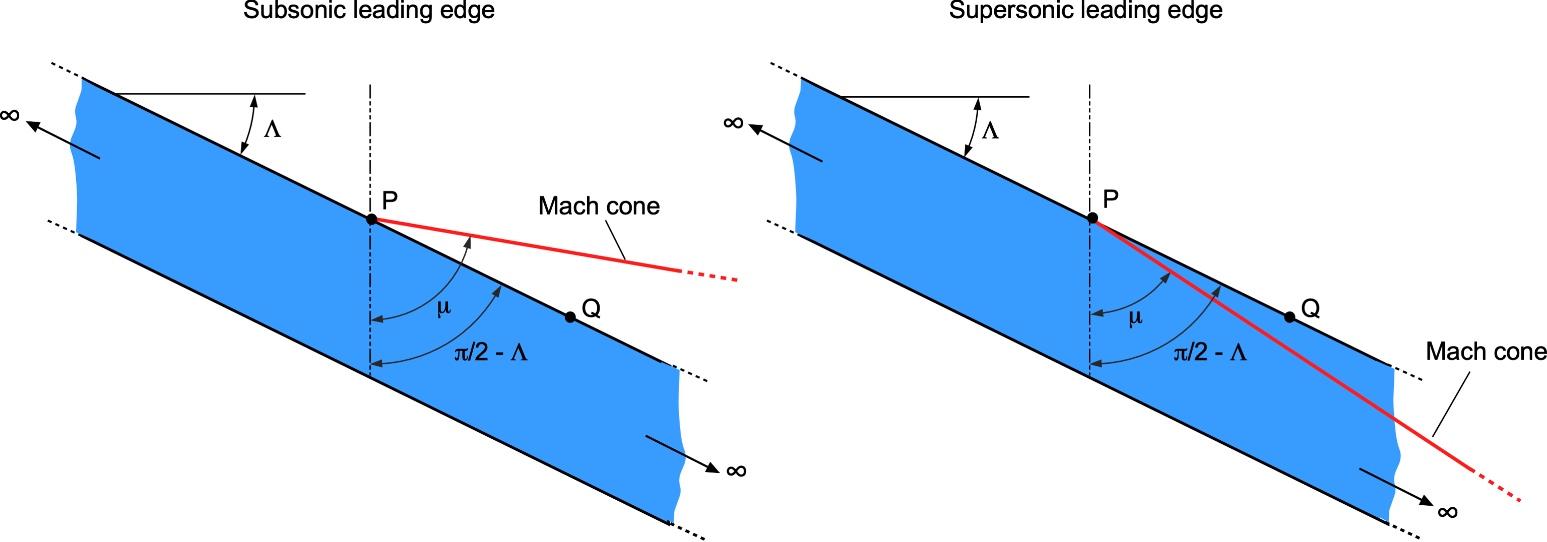
If the component is greater than unity, then the chordwise pressures and wing loadings will be the same as those on an unswept wing in a supersonic free-stream of Mach number . In this case, point Q is outside the Mach cone from all points such as P, and the wing is said to have a supersonic leading edge, i.e.,
(14) 
which means
(15) 
so  . It becomes clear, therefore, that a wing flying with a supersonic leading edge will create larger wave drag.
Therefore, a desirable design goal is to use a subsonic leading edge, forming a series of oblique shocks to gradually slow down the airflow. If obtained, the result is a smoother transition and reduced drag rise compared to the abrupt changes associated with normal shocks in supersonic flow. These preceding arguments, however, only apply to a wing of infinite span, which in practice means any part of a finite span wing where the flow can be considered nominally two-dimensional, i.e., away from the wing tips.
The use of wing sweepback to reduce (wave) drag is most effective for larger aspect ratio wings because sweep also reduces the effective aspect ratio of the wing. The disadvantage of using sweepback is that less lift is produced at a given angle of attack because of the lower effective free-stream velocity, which increases the airplane’s stall airspeed. The lower effective aspect ratio also gives a higher induced drag on the wing during subsonic operation.
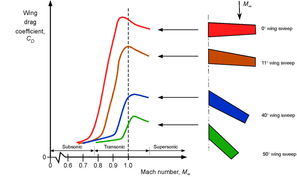
The figure below, derived from wind tunnel measurements, summarizes how wing sweep angle profoundly affects high subsonic, transonic, and supersonic drag. As is now apparent, this effect arises because swept-back wings reduce the wave drag and prevent the shocks from interfering with the flow over the wings, which can create flow separation and a further increase in drag. Notice that sweep delays the rise of the transonic drag and reduces the rate at which the drag increases in the transonic regime. However, although swept wings can help delay this drag rise from compressibility effects, other aerodynamic, higher structural weight, and aeroelastic problems can also be associated with swept wings. Therefore, in practice, airplane designers tend to use as little wing sweep as possible to accomplish the aerodynamic goals, with 20 to 30 degrees of sweep being typical of modern commercial jet airliners.
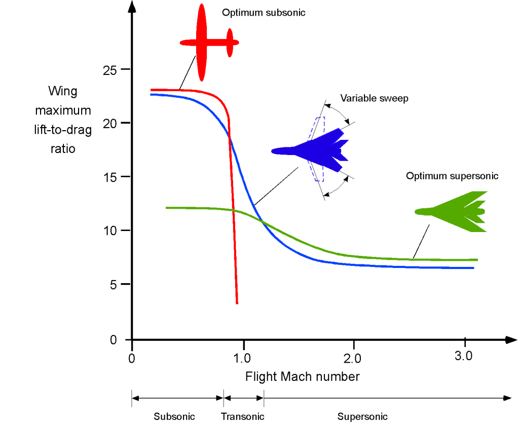
The effects of sweep angle are also summarized in the figure below, which shows the lift-to-drag ratio of a swept wing versus an unswept wing as a function of flight Mach number. In light of the preceding analysis, it becomes clear why some sweepback of a wing can minimize transonic and supersonic drag. On the one hand, as an airplane with an unswept wing approaches Mach 1, its drag increases rapidly, and its lift-to-drag ratio plummets immediately. On the other hand, it can be seen that the highly swept delta wing has a much lower lift-to-drag ratio at lower Mach numbers compared to the unswept wing, but it has a much more acceptable lift-to-drag ratio in supersonic flight.
Therefore, there must be trades and design compromises when selecting the sweep angle of an airplane wing. A highly swept wing with a completely subsonic leading edge will perform very well at supersonic speeds but at the cost of poorer low-speed performance. Recall that a swept wing produces less lift than an equivalent unswept wing, resulting in a higher stall speed and also less maneuver capability because of the lower stall margin. This is why some airplanes, including the B-1 bomber, the F-14, and Tornado fighters, use variable-sweep wings to merge the benefits of unswept and swept wings over the full Mach number envelope of the airplane. However, this aerodynamic advantage comes at the price of structural complexity and weight, amongst other issues.
Delta Wing Supersonic Designs
For sustained supersonic flight, it is known that a delta or triangular wing is close to the optimal type of supersonic wing planform, first theoretically defined by R. T. Jones in 1947 and has since been confirmed using wind tunnel and flight test measurements. The advantage of a delta wing is that it can have a larger sweep angle and a greater wing area than a wing that is just swept back. However, it has also been found that other wing platforms can give similar aerodynamic benefits of low wave drag in supersonic flight.
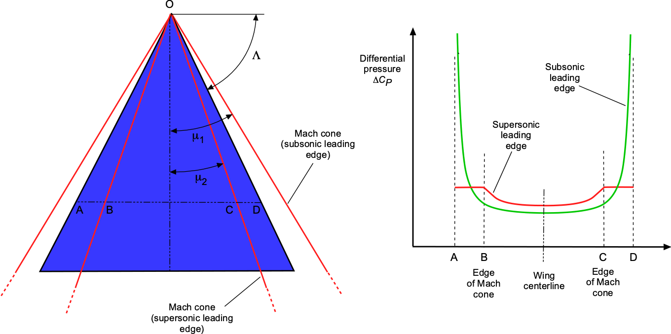
For a delta wing, the flow is conical from the apex of the wing at O, as shown in the figure below. The pressure is constant along any radius vector from O. Two cases must be considered: 1. Subsonic leading edge; 2. Supersonic leading edge. With the subsonic leading edge then  . In this case, as shown by the figure, there is a low leading edge pressure (suction) over AB and CD, but the average pressures are less than for a two-dimensional wing with no sweep. With a supersonic leading edge, then . It is found that the average pressures across AB and CD equal that for a two-dimensional wing with no sweep.
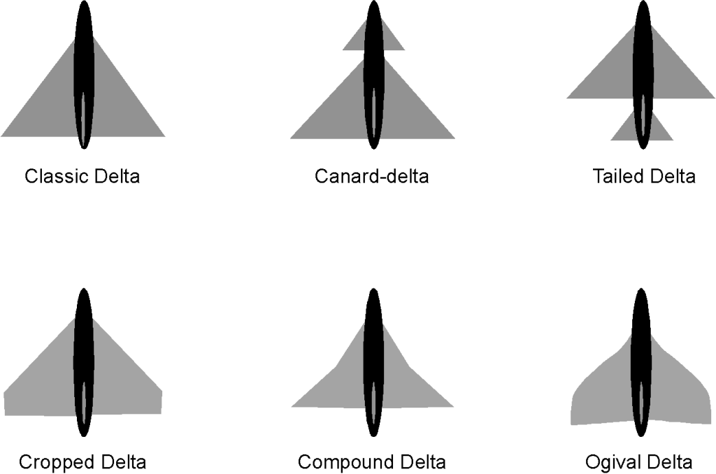
Many variations of the delta wing design have since emerged in the evolution of more efficient supersonic airplanes, as shown in the figure below. The tailless delta wing is the classic design, although experience has shown it could be better from a flight handling qualities perspective. To this end, tailed delta wings have improved the airplane’s pitch control and overall handling qualities, especially when transitioning to and from supersonic flight. In addition, compound and ogival delta wings have been found to have better low-speed and high-angle-of-attack characteristics, while still having all of the advantages of supersonic flight.
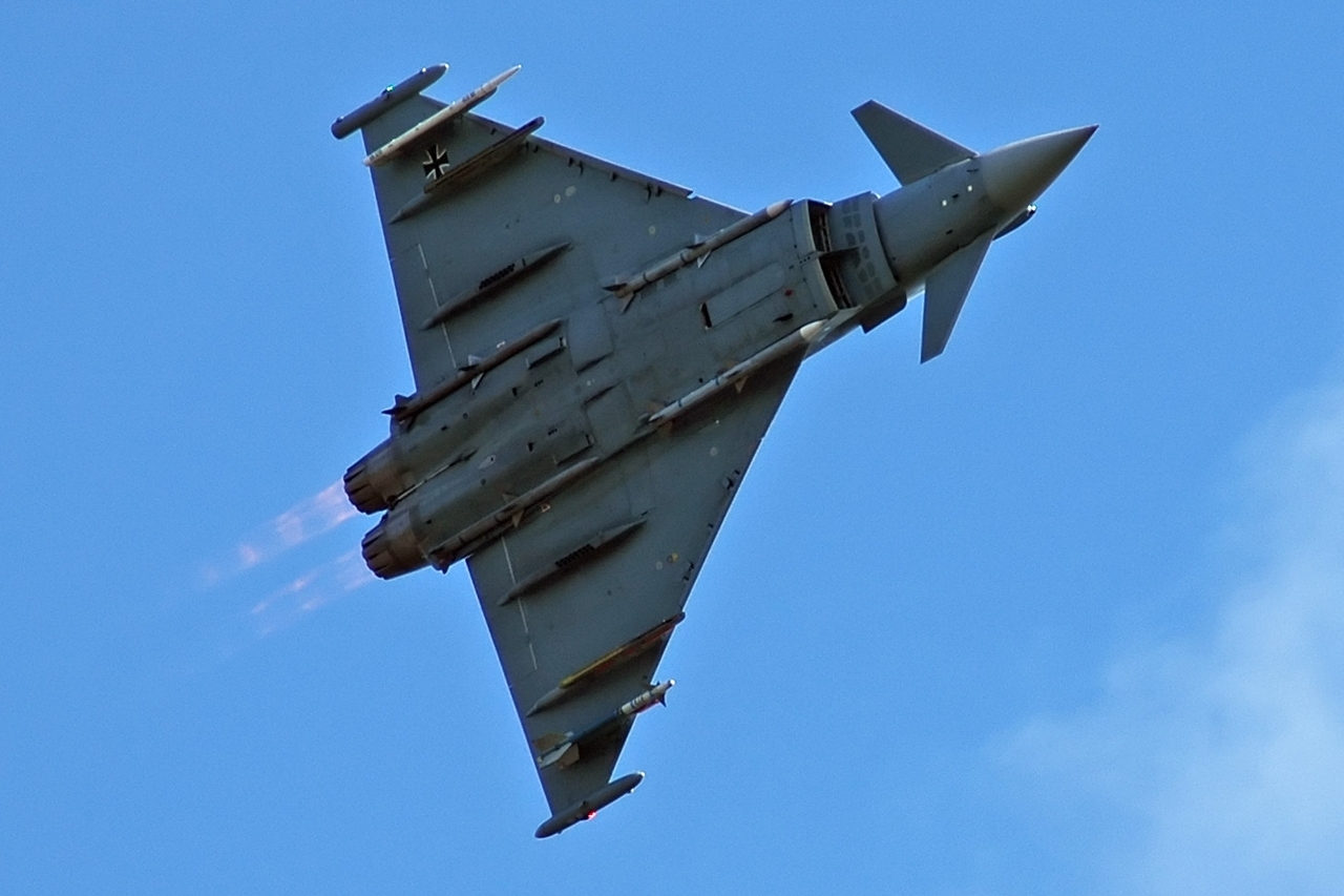
The closely-coupled canard delta configuration is popular because it gives better overall flight characteristics and handling qualities for both supersonic and subsonic flight. The design of supersonic fighter airplanes, including the Eurofighter Typhoon, has become standard, as shown in the photograph below. This closely coupled configuration has a smaller “all-flying” delta fore-plane or canard in front of and above the main delta wing. This canard delta configuration beneficially modifies the airflow over the wing at high angles of attack, keeping it more attached and giving the airplane lower landing speeds and better handling qualities. The all-flying delta-shaped foreplane also gives significant pitching moment authority for control, trim, and maneuverability.
Several other issues have emerged when using pure delta-wing airplanes, including:
1. Controlling the significant changes in pitching moments on the airplane relative to its center of gravity as it transitioned to and from a supersonic flight is difficult to trim with the normal use of the flight controls on the wing.
2. Concerns about the airplane’s low-speed flight characteristics, the thin wings being prone to stall at low angles of attack, and a susceptibility to develop a behavior known as wing rock. Therefore, the early delta-wing airplanes had high landing speeds, raising many operational challenges.
3. Because relatively thin wings were needed for aerodynamic reasons, obtaining the required structural strength and stiffness while ensuring the wing was free from aeroelastic twisting and flutter issues was challenging.
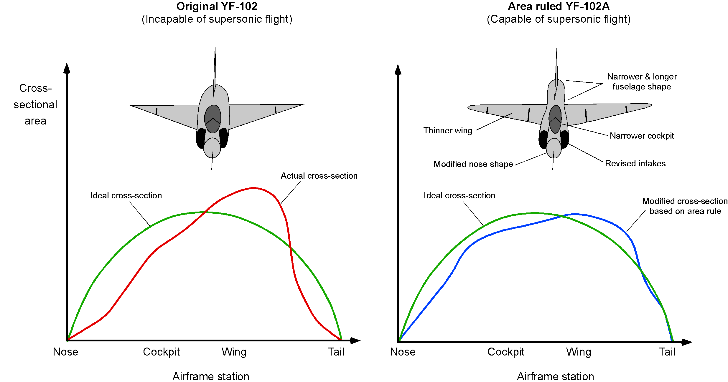
With a delta wing or one of its variants, the supersonic wave drag may be minimized further by employing Whitcomb’s Area Rule along the length of a slender fuselage. This rule can also be used to improve the spanwise lift distribution over the wing as it passes the fuselage; Dietrich Küchemann had originally hypothesized these ideas during WW2. The subtle use of the Area Rule is often noted when examining the fuselage shapes of supersonic fighter airplanes, which may have carefully contoured fuselage shapes to give smooth variations in the cross-sectional shape of the airplane. A constraint in this aerodynamic shaping process for a fighter is engine integration because the fuselage must contain the engine, the afterburner, and all the engine-associated systems.
Variable Sweep Supersonic Wing Designs
To widen an airplane’s flight envelope, designers strive to meld the benefits of different airplane shapes that perform well in various flight regimes. For example, combining the benefits of efficient subsonic and supersonic flight is desirable. As shown below, these benefits can be accomplished using a variable-sweep or “swing-wing” design. However, it is not always a possible engineering solution, partly because of the extra mechanical complexity and a significant weight penalty.

There can be several missions where a supersonic capability combined with good subsonic efficiency is a highly desirable characteristic. For example, a mission may require an efficient subsonic cruise over large distances, conserving fuel, followed by a shorter supersonic flight to the target, and then a subsonic cruise to return to base. The variable sweep or “swing-wing” design can also better maintain trim as the center of lift on the wing changes from subsonic to supersonic flight and back again, and there is also a center of gravity movement. On the F-14, F-111, and B-1 supersonic bombers, the wings are swept forward for takeoff and landing, significantly reducing the stall speed and improving the low-speed handling qualities.
The lift-to-drag ratio of the F-111 airplane for both subsonic and supersonic flight is shown in the figure below. Notice the improvement in the lift-to-drag ratio as the wings are swept forward, which is an expected behavior based on the corresponding increase in wing aspect ratio. A lift-to-drag ratio between 4 and 5 in supersonic flight is typical for any swept delta-wing airplane.
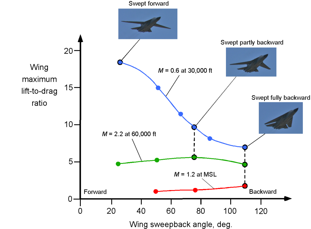
One disadvantage of such a swing-wing airplane is the added structural weight and complexity of the sweep pivot joint and associated actuator mechanisms. Also, variable geometry wings are more challenging to make stealthy, which is a big concern for the military.
Examining any military fighter airplane will show that wing pylons are generally always needed to carry bombs, air-launched weapons, and long-range fuel tanks. Therefore, another disadvantage of a variable-sweep wing is that pylon stations on the wing’s outer (swing) part are only possible if they can be mechanically designed to be reoriented to point into the relative flow. Pivoting pylons have been used on some airplanes with variable geometry. While they incur a weight penalty, they can significantly enhance the airplane’s capabilities in that it can now carry weapons or external fuel tanks.
Pivoting wing pylon systems for external stores and weapons carriage have been used on the General Dynamics F-111 and the Panavia Tornado to keep them facing into the flow as the wing sweeps backward and forward. Mechanically, this can be done using a form of pantograph, with one end fixed to the fuselage and the other to the pylon. The F-111’s outermost pair of pylons did not swivel and were only used while the wing was swept fully forward, restricting the airplanes to fly only subsonic flight with fuel tanks, such as for long-range ferry flights.
Engines for Supersonic Flight
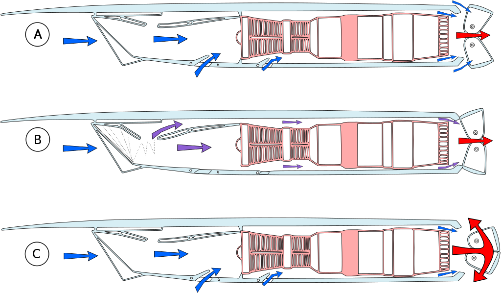
Engines for supersonic airplanes have ranged from rocket engines to turbojets to turbofans. In supersonic flight, the inlet to an engine must be designed so that the intake to the compressor occurs at subsonic speeds. This goal is achieved by using a duct and/or doors or baffles to give a total pressure recovery at the end of the inlet diffuser before it reaches the compressor stage, as shown in the image below for the Roll-Royce/Snecma Olympus 593 engines used to power the Concorde.
The thrust from a turbojet engine tends to increase linearly with increasing supersonic flight Mach number because of the increased mass flow rate through the engine at supersonic speeds. Still, their relatively high specific fuel consumption can be an issue. While many supersonic airplanes have used turbojet engines with afterburners, the low bypass turbofan (with an afterburner) can be designed to give much better propulsive efficiency over a broader range of flight Mach numbers, thereby giving the airplane good fuel consumption throughout its flight envelope.
However, maintaining an efficient supersonic cruise for extended flight times is a continuing challenge with any supersonic airplane. Therefore, besides the engine requirements, there is always a need for low supersonic drag, so the airframes must be highly streamlined, and the wings have to be relatively thin with short wingspans.
Supersonic Transport (SST) Airplanes
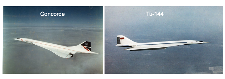
There was much interest in developing supersonic transport (SST) airplanes during the 1960s, with technical efforts being led by the British and French. The Anglo-French Concorde became the World’s first SST, which flew first in 1969 and went into operational service in 1976. The Concorde used a tailless ogival-shaped “slender-delta” wing, carefully designed to give good lift-to-drag in supersonic flight but also acceptable low-speed flight characteristics for takeoff and landing.
The Russians soon followed with the Tupolev Tu-144, which resembled the Concorde but was distinctive in its use of retractable foreplane canards. Both the Concorde and Tu-144 were designed for cruising at just over Mach 2 at 60,000 feet, which was the highest Mach number that could be obtained without excessive kinetic heating of the airframe. As a result, both the Concorde and the Tu-144 used special aluminum alloys in their construction and various other design features to allow the airframe to expand during flight. Conventional airplanes use various aluminum alloys, but these materials tend to soften and lose their strength at the temperatures produced by kinetic heating at Mach 2 and above.
Only 14 Concorde SSTs were built, and the airplane was never economically viable for broader airline service. Nevertheless, it was a very popular airplane with both the passengers and the flight crews alike. British Airways and Air France flew the Concorde for over 25 years until it was abruptly retired in 2003 after a crash. The British Airways Concorde fleet made 50,000 flights and collectively flew more than 2.5 million passengers. With a take-off speed of about 220 knots (250 mph) and a cruising speed of 1,350 mph, which was just a little more than twice the speed of sound, a typical London to New York crossing was accomplished in 3-1/2 hours, compared to 8 hours for a subsonic flight. The Concorde holds many aviation records, including the fastest transatlantic airliner flight (New York JFK to London Heathrow) in 2 hours and 53 minutes. However, the Tu-144 was unsuccessful as a commercial airplane. After two crashes, including one on a delivery flight to Aeroflot, it was permanently retired after only 55 passenger flights.
In the 1970s, Boeing planned to develop an SST, initially using a variable geometry or “swing-wing” design, the final evolution of the concept shown in the figure below. The idea of the swing-wing design has already been discussed, which, for civil airplanes, could allow them to fly efficiently at subsonic speeds over land and inside terminal areas while having all the advantages of an efficient supersonic cruise.
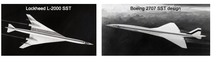
However, despite the potential aerodynamic benefits of a swing-wing concept, the detailed engineering analyses done by Boeing proved too challenging from an airframe weight perspective. Boeing’s final 2707 SST concept was a more conventional supersonic delta-shaped wing. The Boeing design was also much larger than the Concorde or the Tu-144 and was intended to cruise at Mach 3. However, compounding the technical problems, high development costs, concern about sonic booms, and the lack of a passenger market for the airlines, eventually led to its cancellation.
Slender Delta Concept
Like most delta-wing fighter-type airplanes, they do not have good aerodynamic characteristics at low flight speeds and high angles of attack, such as during takeoff and landing. Takeoff and landing speeds are high for such airplanes, requiring long runways. Concorde was specially designed to use a vortex-lift concept to improve the low-speed, high-angle of attack flight. The airplane had no high lift devices, so to reduce the landing speeds, the wing was designed to promote a phenomenon called vortex lift.
In the early 1950s, Weber and Küchemann at the RAE (Royal Aircraft Establishment) in the U.K. published a series of papers on a new type of delta-wing planform known as the “slender delta” concept. If designed appropriately, delta wings could produce robust and stable vortex flows on their upper surfaces at low airspeeds and high angles of attack, as shown in the schematic below. The presence of these vortices creates very low-pressure zones and so causes the lift on the wing to be significantly increased. All modern supersonic airplanes are explicitly designed to take advantage of the benefits of vortex lift at low airspeeds.
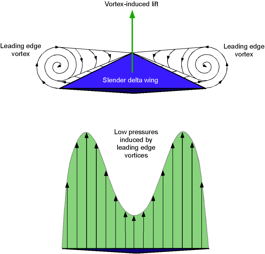
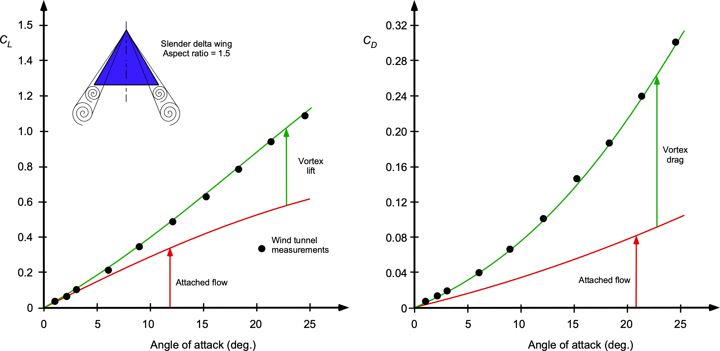
Weber and Küchemann determined that the lift from the leading-edge vortex flows could be maximized by increasing the slenderness of the wing and drooping the leading-edge camber somewhat. This approach would retain good supersonic performance but also allow for high values of maximum lift at low airspeeds, as shown in the figure below, offering much lower takeoff and landing speeds. The unfortunate byproduct is also a large increase in drag, which requires considerable thrust and power to overcome, even when landing.
However, Concorde had to be flown at an extremely high angle of attack to achieve this condition, which was a distinctive (if not rather alarming) flight attitude during takeoffs and landings. Indeed, the angle of attack on takeoff and landing was so high that the airplane was designed with a “drooped-nose” feature to allow the pilots to see over the nose of the airplane. Concorde was also distinctive because of its exceptionally tall landing gear, which was needed to enable the airplane to rotate to the required angle of attack for takeoff without the tail striking the runway.
Any Future for SSTs?
The Anglo-French Concorde remains the only successful SST so far. Although many other SST designs have been studied, it remains to be seen if any future SST concept will ever prove economically viable for scheduled airline service. The inherently much lower lift-to-drag ratios of airplanes flying at supersonic speeds, even if the wing and airplane as a whole are highly aerodynamically and structurally optimized, means that SSTs will always burn much more fuel over a given range than subsonic airplane designs. The resulting seat-mile costs are considerably higher than those of a subsonic airplane (perhaps 3 to 5 times or more), even though the advantage is that the airplane’s flight time is less because it can cover the same distance in less than half the time.
However, the maximum achievable range of a supersonic airliner will always be much less than a subsonic airliner because of the higher fuel burn. Like the Concorde, the trans-Atlantic routes for a Mach > 2 capable SST are undoubtedly feasible. However, for longer ranges, such as over the Pacific from the USA to Asia or Australia, stops for refueling will be needed, and will likely erode any speed advantage, especially for only a Mach 1.5 to 1.7 capable SST. Longer ranges may also be required using alternative routings to minimize the effects of sonic booms over land, eroding any potential speed advantage unless the SST is capable of Mach 2 or greater.
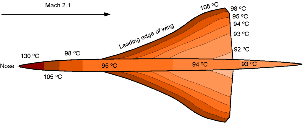
Kinetic Heating
A serious problem facing supersonic (and hypersonic) flight vehicles is the airframe’s kinetic heating caused by air friction, which, for the Concorde, was a serious concern at the design stage. The graphic below illustrates just how hot the different parts of the Concorde became at its cruise speed of Mach 2.1. The skin temperature ranged from a peak of 130C at the nose to 93C at the tail, which caused the airplane to expand about 18 cm or 7 inches in length during its flight. The airframe expansion meant that some special structural design features were needed to allow the airframe to expand without setting up high structural stresses.
Traditional aluminum alloys cannot survive these high temperatures, so unique materials had to be developed to build Concorde. To this end, high-temperature aluminum alloys were used for its construction, including light alloy Hiduminium RR58, high-temperature steel, stainless honeycomb, and resin-bonded glass composites. Hiduminium RR58, which has a much higher melting point than conventional aluminum alloy, was used for most of Concorde’s structure. In addition, steel was used for sections subjected to even higher temperatures and the highest loads, and resin-bonded glass fiber was used for regions with the highest skin temperature, such as at the nose.
Sonic Booms
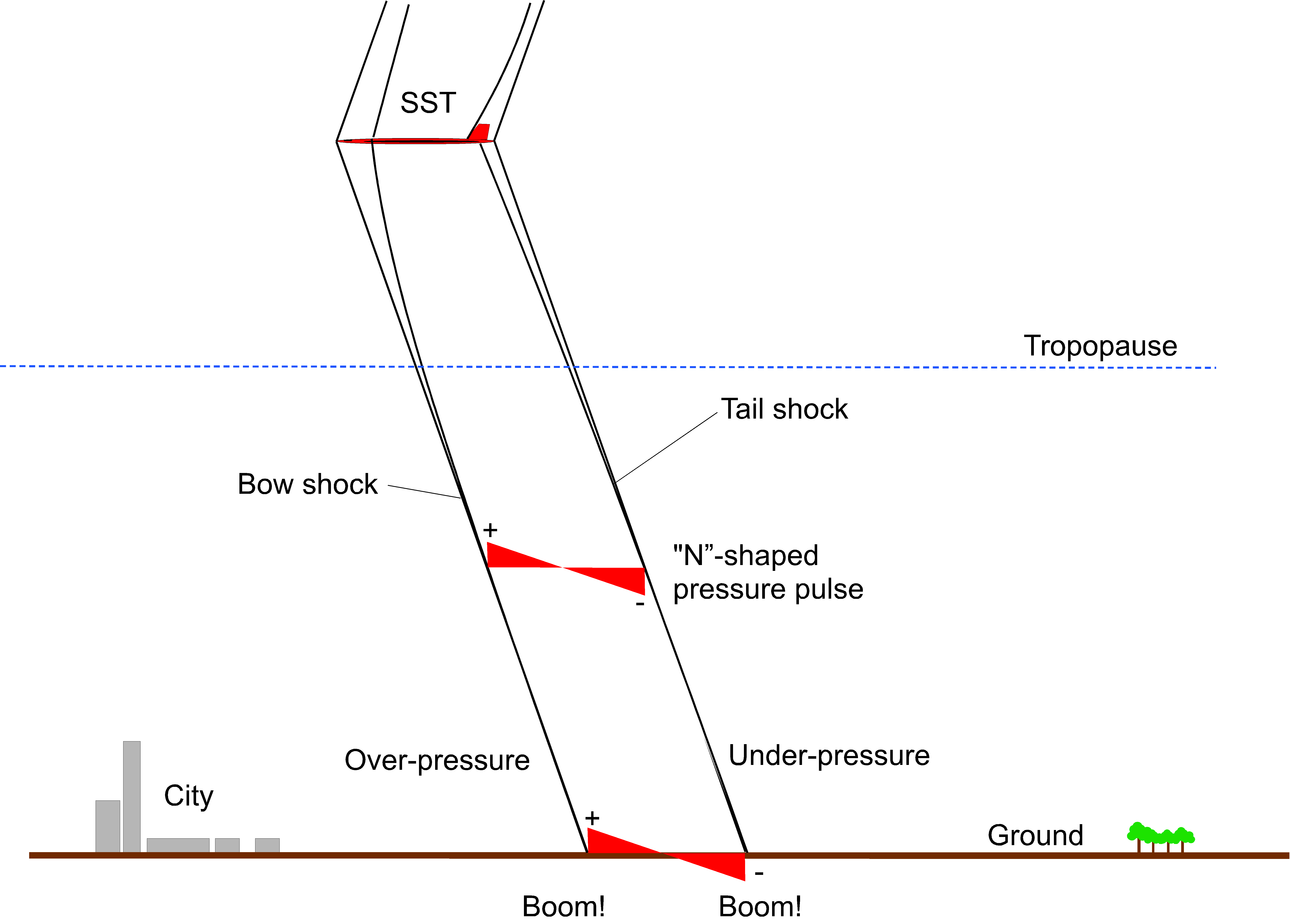
A problem facing SSTs (as well as any other type of supersonic or hypersonic flight vehicle) is the production of sonic booms. The leading and trailing shock waves formed by a supersonic airplane (one shock at the nose called the bow shock and another at the tail) appear to an observer on the ground as a pressure pulse in the form of an overpressure and an under-pressure, as shown in the schematic below. This pressure change is heard (and felt) by an observer on the ground as an impulsive “boom-boom” noise. Besides being annoying, if not startling, the intensity of the pressure pulse from Concorde produced noise levels over 135 dB, enough to rattle or break windows on buildings. Nevertheless, research continues into ways of mitigating sonic booms.
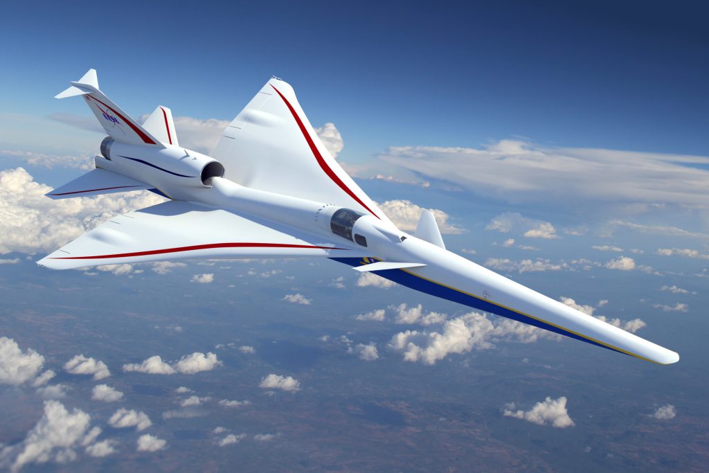
In 2017, NASA issued a draft request for proposals for developing its Quiet Supersonic Transport (QueSST) low-boom flight demonstrator. This program called for designing and testing a new X-plane to support the development of future-generation SST concepts. The contract was awarded to Lockheed Martin, and its Skunk Works X-59 supersonic demonstrator, as shown in the artist’s rendering below, is expected to cruise at 55,000 feet and Mach 1.4. One purpose of the flight tests will be to help quantify community response to supersonic flight over land. Still, this is unlikely to change the public’s opinion after the psycho-acoustic supersonic flight tests done over London in the 1960s. As of December 2023, the X-59 airplane had been constructed and readied for its first flights in 2024.
Smaller supersonic transport airplanes, such as supersonic business jets (SSBJs), have received more recent attention than larger commercial SSTs. Several companies are proposing SSBJ concepts, intending to transport as few as 10 to as many as 80 passengers. Typically, SSBJs would be about twice the size of a typical subsonic business jet but much smaller than Concorde.
However, the potential SST players face immense technical, certification, and economic challenges, including a hefty dose of public skepticism. One startup, Boom Supersonic, claims to have a Mach 1.7 capable SST in development, and it will fly with airlines by 2029. One major technical issue is finding engines in a civil market with no engine manufacturers, making engines suitable for supersonic flight, at least for civil applications. In addition, the cost of developing a new engine could be prohibitive for most manufacturers based on the minimal potential market demand for SSTs. Maintenance and repair costs for an SST are also likely to be considerably higher because of the stresses imposed on the airframe and engines during high-speed flight, potentially increasing downtime and the availability of the airplane.
Gaining certification from civil airworthiness authorities is a significant issue for an SST, and it is likely to be a protected affair. For example, Concorde required over 4,000 hours of certification testing over seven years and 1,000 hours of route-proving in typical airline service conditions. Considering that the U.S. and European airworthiness authorities currently prohibit supersonic aircraft from flying over land, all other issues may be moot.
Several groups believe that the technical issues, economic concerns, sonic booms, emissions, certification, etc., can be solved at a smaller scale, potentially opening up a significant future supersonic market for airlines and others. However, it remains to be seen if this will come true in the decades to come. To make a supersonic airplane commercially viable, airlines will likely have to charge higher ticket prices than subsonic airplanes, limiting the market to passengers willing to pay this premium. Nevertheless, the appeal of vastly reduced traveling time by flying at supersonic speeds remains attractive to some passengers, not least for the novelty value of flying supersonically. Still, the overall economics remain questionable for the airlines, even for the business jet market. It is fair to say that it is unlikely that passengers will be flying supersonic anytime soon.
Hypersonic Flight
Hypersonic flight is defined as flight at speeds at or beyond Mach 5. However, unlike what happens as the aircraft approaches Mach 1, there are no distinctive changes in the flow characteristics as an aircraft reaches hypersonic Mach numbers. Such high Mach numbers have only been achieved by rockets, re-entry spacecraft, and special high-altitude research aircraft. Theodore von Kármán was one of the first to analyze the problems of hypersonic flight, stating: “At such speeds, even in rarified air, the surface will be heated to the temperatures none of the known materials can withstand. The problem of the thermal barrier is much more complicated than the problem of the sound barrier.”
Challenges
When flight vehicles begin to fly at hypersonic Mach numbers, many additional aerodynamic and other technical challenges occur, a summary of which is shown in the figure below. The main issues include the proximity of the shock waves to the vehicle, kinetic heating, viscous interactions, chemical reactions, and surface erosion.
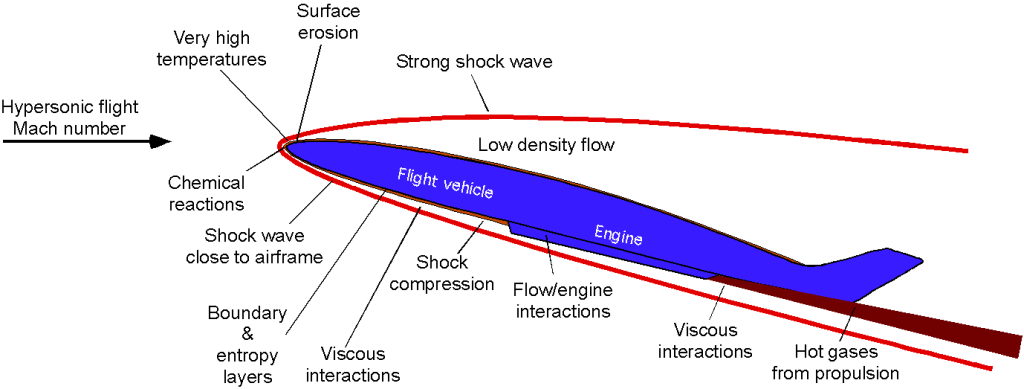
In more detail, these effects at hypersonic flight Mach numbers include, but are not limited to, the following:
1. The Mach angle is small (see Eq. 11), so the shock waves bend back to steep angles and can begin to interact with the airframe, which causes disruptions to the flow in the boundary layer. Usually, the boundary layer is relatively thin, even laminar. Still, the resulting flow field becomes very complex at hypersonic speeds as the shock waves touch the boundary layer, and flow separation is likely.
2. The shock waves are very strong at hypersonic speeds, and the air undergoes significant temperature changes that affect its chemistry. The need to include chemistry in any aerodynamic analysis of hypersonic flows significantly raises the complexity of the needed predictive methods.
3. The proximity of shock waves to the body and the effects of skin friction cause a large amount of aerodynamic heating on vehicles flying at hypersonic speeds. Even high-temperature aluminum and titanium commonly used for supersonic aircraft construction will melt.
4. The flow over the vehicle can strongly interact with the propulsion system. In this regard, the propulsion system design must be tightly integrated into the entire vehicle design. Usually, a hypersonic vehicle must be designed so that its shape pre-compresses the air before it enters the engine.
5. The sonic booms from aircraft flying at Mach > 3 and hypersonically will be loud enough to likely damage structures on the ground and permanently damage human ears. It is unlikely that a hypersonic flight vehicle of any significant size could be allowed to fly over populated areas. Nevertheless, this technical challenge will remain in the future.
History
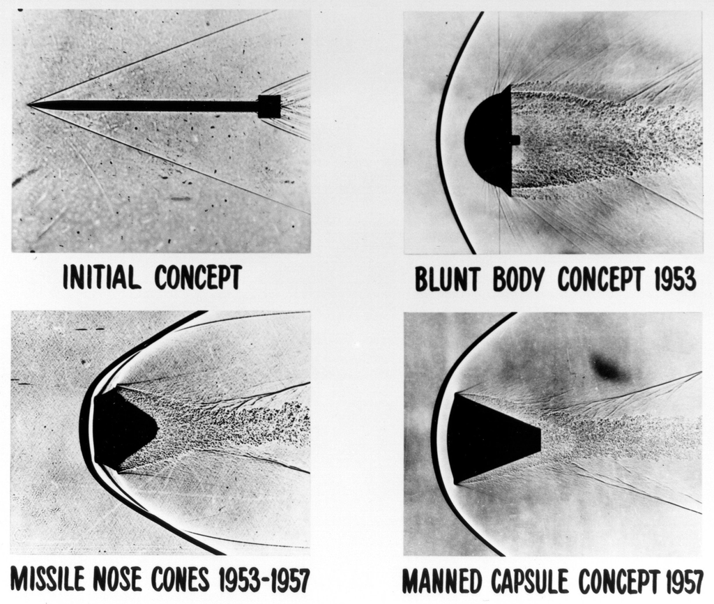
The issues associated with hypersonic flight first became apparent in the 1950s with the further development of WW2 ballistic missiles capable of flying at Mach 5. However, for such missiles to have an intercontinental range, it was necessary to launch them out of the Earth’s atmosphere into space and then re-enter the atmosphere much nearer to the target. When tests on the first of such missiles were made based on the German designs, which had very pointed nose shapes, they completely melted during the re-entry phase from the intense shock waves and aerodynamic heating at Mach 5 and higher.
The answer to this problem, which was research led by H. Julian Allen & Alfred Eggers at the NACA, was opposite to that expected based on conventional aerodynamic wisdom, which was to make the nose of the missile much more rounded, as shown in the schlieren visualization images below. This “blunt body” design created a shock wave that stood off the nose and caused a boundary layer to flow over the nose cone’s surface, preventing the excessive heat of re-entry from melting the structure. In contrast, pointed nose shapes allowed the shock wave to touch the surface with a boundary layer that was too thin to offer much thermal protection. Tests with the modified missiles confirmed the validity of this method, although the nose still needed to be made of high-temperature resistant materials.
The information gained about high-speed flight and hypersonics in the wind tunnel and through flight tests contributed significantly to the development of the Mercury, Gemini, and Apollo space flight programs. Flight test work on hypersonics was first conducted by the U.S. Air Force and NASA during the 1950s. The X-15 research airplane flew for nearly ten years from 1959 and set the world’s unofficial speed and altitude records of 4,520 mph (Mach 6.7) and 354,200 feet during a program to investigate all aspects of piloted hypersonic flight.
The X-17 was a missile program that used a three-stage rocket to get the nose section to reach conditions between Mach 10 and 20 in the lower atmosphere. The nose cones survived briefly before vaporizing but long enough for valuable measurements to be made. Ultimately, the solution of minimizing kinetic heating effects on re-entry vehicles was also to use ablative materials to help shed the heat buildup.
During the 1980s, NASA began considering a single-stage hypersonic flight vehicle to replace the Space Shuttle. The National Aerospace Plane (NASP) was intended to take off from a standard runway used by airliners. Once the aircraft had reached sufficient airspeed, scramjet engines would power the aircraft into hypersonic flight. Finally, a rocket system would take the NASP into orbit. The NASP eventually became the Rockwell X-30 research vehicle. While the project did not reach the flight stage, a one-third-scale demonstrator, the X-43, was built. Three were built, the first being destroyed after an in-flight malfunction, but the other two flew successfully with the scramjet operating for approximately 10 seconds.
Hypersonic “Newtonian” Theory
Like all flight vehicle design aspects, the ability to predict quantitatively aerodynamic forces for the right (physical) reason is fundamental. To this end, a relatively parsimonious but validated method must often be used, providing the necessary focus to establish initial designs from which more detailed analysis can follow. Isaac Newton did not know about shock waves or supersonic or hypersonic flows. Still, in his Principia of 1687, he hypothesized some simple hydrodynamic principles, which have seen application to hypersonic flows in recent decades.
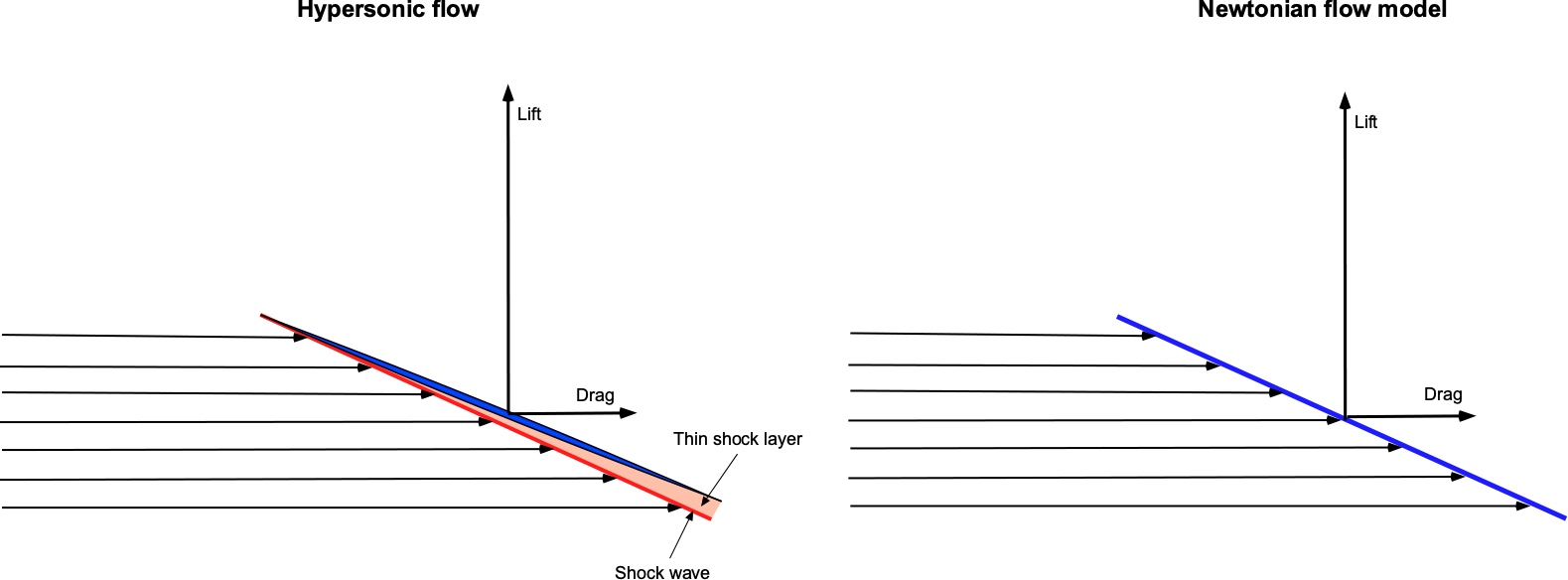
Isaac Newton proposed that fluid flow forces exerted on a surface consisting of a uniform stream of “particles” in which the time rate of change of the normal component of the momentum of each particle would be transferred to the plate, whereas the tangential component would be preserved. He assumed that the upper surface always remains in the “shadow” of the flow and is hence uninfluenced by the free-stream flow.
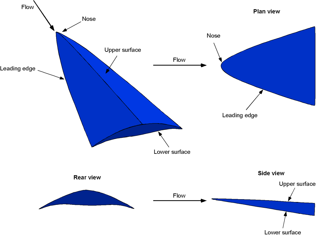
The figure below shows a hypersonic flow impinging on a thin body, resulting in a shock wave close to the surface and a thin shock layer. In a supersonic flow, disturbances cannot be propagated upstream, so there is no streamline curvature as the flow approaches the wing. Indeed, the resulting flow field looks remarkably like that proposed by Newton more than three centuries ago, despite the physical disparity in detail. Indeed, although the so-called Newtonian aerodynamics theory is flawed for several reasons, it is a reasonably good model to describe the lift and drag of bodies in hypersonic flows.
It can be shown that the lift coefficient in the “Newtonian theory” on a flat surface at an angle of attack to the flow is given by
(16) 
and the corresponding drag coefficient on the surface is
(17) 
The resulting lift-to-drag ratio is, therefore,
(18) 
While the Newtonian “hypersonic” theory is elementary, at least in terms of predicting the lift and drag coefficients, the question is how well it might work in practice, i.e., can it be used to predict anything useful? To this end, the results shown in the figures below compare the Newtonian theory with NASA wind tunnel measurements on a hypersonic body at Mach numbers of 6 and 10; measurements are available for angles of attack of -5o to 35o at Mach numbers from 1.5 to 10.
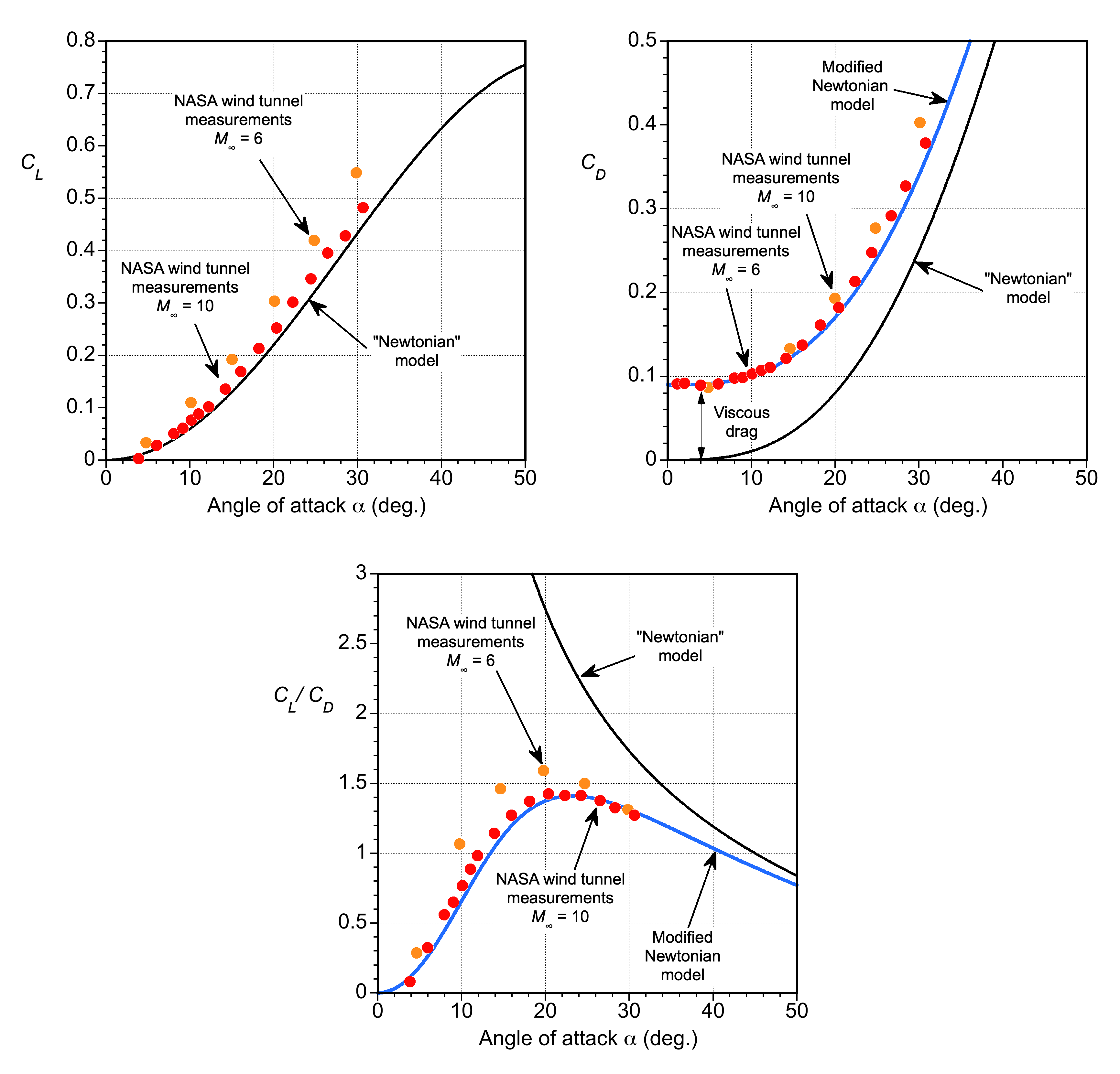
Notice that despite its simplicity, the Newtonian theory is in remarkable agreement with the measurements. The drag is underpredicted because the Newtonian theory does not account for wave drag and viscous effects. However, the drag equation can be modified empirically to
(19) 
where  is a constant that will depend on the specific body shape. In this case, a value of
  aligns well with the wind tunnel measurements. The corresponding lift-to-drag ratio now becomes
(20) 
which again is seen to be in good agreement with the wind tunnel measurements. Notice that in the absence of viscous effects, the Newtonian theory becomes singular at zero angle of attack, but this is of no practical significance.
It can be concluded that despite its limitations, Newtonian “hypersonic” aerodynamics can still be used in some instances to provide reasonable estimates and initial approximations for aerodynamic lift and drag. Therefore, it can be useful in conceptual design studies or in situations where a rapid assessment of the aerodynamic characteristics of a hypersonic vehicle is required.
Other Methods
To obtain more accurate predictions for hypersonic flow about various bodies, researchers and engineers rely on more advanced approaches such as shock-expansion theory, computational fluid dynamics (CFD), and wind tunnel testing. CFD methods consider the complexities and non-idealities of hypersonic flows, including shock wave interactions, boundary layer effects, chemical reactions, and high-temperature gas dynamics. If properly conducted, wind tunnel testing represents the datum or benchmark against which CFD methods can be tested and validated.
Shock expansion theory is another popular method, which involves the analysis of fluid flow containing both shock and expansion waves. On the one hand, shock waves are abrupt changes in a fluid’s pressure, temperature, and density caused by the propagation of a disturbance through the fluid. On the other hand, expansion waves are gradual changes in these properties caused by the spreading out of the fluid. The oblique shock relations and the Prandtl-Meyer function can be used to find the pressures on the body, allowing lift and drag forces to be obtained by integration.
Hypersonic Aircraft Design
A thin, flat plate is known theoretically to be the most efficient aerodynamic shape for hypersonic flight, its lift-to-drag ratio being the highest achievable. However, a plate is an unrealistic design solution for a practical flight vehicle because of the need to contain engines, fuel, systems, payload, etc. Wind tunnel measurements of candidate hypersonic shapes have shown that their maximum achievable aerodynamic efficiency in terms of lift-to-drag ratio,  , decreases with increasing flight Mach number according to
(21) 
which is often referred to as Küchemann’s equation. The conclusions to be drawn here are that the aerodynamic efficiency is relatively low in hypersonic flight and that increasing the lift-to-drag ratio will be challenging.
To maximize the aerodynamic efficiency of a flight vehicle in hypersonic flight, some general design rules should be followed. Such vehicles should generally be blended with body shapes with integrated forebodies, propulsion systems, and afterbodies. More specifically, they should have as small a frontal area as possible, with a highly streamlined overall shape to minimize surface area. A short-span, low aspect ratio wing should be used, with the fuselage suitably shaped to generate lift, i.e., as a lifting body. The propulsion system must be well-integrated into the vehicle’s overall shape to prevent shock waves from one component from adversely interfering with the flow at another component.
Waveriders
A waverider is another type of hypersonic wing design with an improved lift-to-drag ratio relative to other shapes. This goal is accomplished using the shock waves generated by its flight as a lifting surface, a phenomenon known as compression lift. The waverider concept originated from the work of Terence Nonweiler on winged atmospheric re-entry vehicles in the 1950s. A waverider is a delta wing with some anhedral, often called a caret wing. With the advent of computational fluid dynamics (CFD) and advanced hypersonic prediction methods, various optimized waverider shapes have been developed, as shown in the figure below. However, heat dissipation is an issue with such optimized designs because of the closer proximity of the shock waves to the surfaces.
Propulsion Issues
Achieving combustion and propulsion is another major problem at hypersonic speeds, and the most likely candidate is a variation of a ramjet engine called a scramjet, i.e., a supersonic ramjet, as shown in the figure below. A scramjet engine works on the principle that the shock waves on the vehicle can slow down and compress the air to support combustion inside the engine.
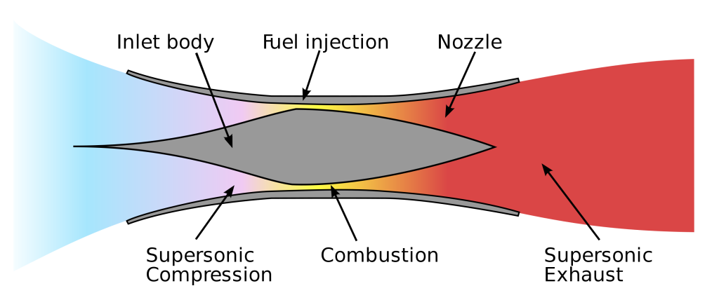
However, a scramjet must be accelerated close to the required flight conditions (usually close to Mach 4) using some other propulsion system, such as a rocket engine. Maintaining continuous combustion in the supersonic flow within the engine has met numerous technical challenges, including the extremely short transit time of the fuel mixture inside the engine to allow combustion.
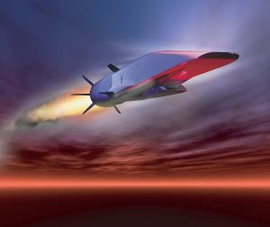
The Boeing X-51A scramjet demonstration aircraft was a waverider concept tested from 2011 to 2013, as shown in the artist’s impression below. The X-51A was used to demonstrate engine operations at hypersonic airspeeds and other aspects of hypersonic flight. The aircraft sustained Mach 5 flight for 200 seconds during its longest tests. Measurements made during these test flights have been used to compare measurements made in hypersonic wind tunnels and predictions made using CFD.
Summary & Closure
Humans have always sought to fly faster, which has led to the development of aerodynamically optimized flight vehicles and advanced propulsion systems for supersonic and hypersonic flight. However, the development and practical implementation of these technologies still involve complex engineering challenges and much research. Solving these challenges requires optimizing vehicle shape to minimize drag and shock wave interactions and developing efficient engines for supersonic and hypersonic flight.
Continued advancements in aerodynamics, propulsion systems, and materials science will eventually lead toward potential future breakthroughs in high-speed flight capabilities. The design of hypersonic engines remains a significant challenge, with scramjets showing some levels of success. Kinetic heating on the airframe at high speeds produces high surface temperatures, requiring unique “high-temperature” materials. The future of hypersonic flight is likely to involve waverider vehicles., which use the shock waves generated by their flight to create lift and reduce drag. By “riding” their shockwaves, these vehicles can potentially achieve better hypersonic efficiency.
Technical issues aside, the economics of a supersonic or even hypersonic aircraft are complex and depend on many factors. Research, design, testing, and certification expenses for such aircraft can be high, and they will need to be recouped through sales and operations. Manufacturing costs are also likely to be much higher than for subsonic aviation because specialized materials and production methods are required. Supersonic aircraft will consume significantly more fuel per passenger and incur higher maintenance and repair costs. Therefore, airlines will likely charge higher ticket prices to make a supersonic airliner commercially viable. The success of any future commercial supersonic transport (SST) aircraft will ultimately depend on passenger demand and competition from existing subsonic options.
5-Question Self-Assessment Quickquiz
For Further Thought or Discussion
- Do some background research to determine what efforts are being explored to reduce the intensity of the “sonic boom” produced by supersonic airplanes.
- Research some engineering issues associated with kinetic heating on a supersonic airplane that cruises between Mach 2 and 3. What kinds of construction materials might be required?
- What kinds of supersonic passenger airplanes, i.e., SSTs, might there be in the future? Explain why their success ultimately depends on the availability of an engine suitable for supersonic flight.
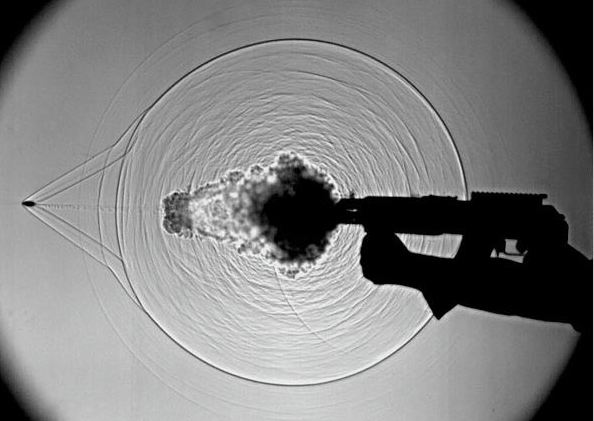
- Study the image below, which is a schlieren flow visualization image of what is produced when a bullet is fired from a gun. Can you explain what is happening here and the origin of all the waves?
- Consider the Mach angle as a function of the Mach number. What happens to the Mach angle at hypersonic Mach numbers, and why is this important?
Other Useful Online Resources
For additional resources on supersonic and hypersonic flight, follow up on some of these online resources:
- Airplanes approaching the sound barrier – another film by Shell Oil.
- High-speed flight: Part 1, and Parts 2 & 3.
- Video about the World’s fastest subsonic airliner: The Convair 990A Coronado.
- Hypersonic Waverider – How the USAF X-51A scramjet works – see the video here.
- The Insane Engineering of the X-15 – see the video here.
- The Lockheed A-12 – speed matters!
- The SR-71 Blackbird – the king of speed!
- Project canceled: BAC TSR2 – The British Cold War strike and reconnaissance aircraft that was canceled.
- Great video about the English Electric Lightning –The British supersonic fighter and interceptor aircraft.
- Video about the World’s fastest bomber: The Mach 3 capable XB-70 Valkyrie.
- Death of a Valkyrie: The 1966 XB-70 Midair Collision
- Kelly Johnson and the Skunk Works. The genius that changed aviation.
