4 Mathematics for Engineering
Introduction
“Omnia de mathematica agitur!“[1] Many will say that mathematics is the engineer’s language, so the first thing students need to do before they can study engineering is to learn (or relearn) the essential mathematics. Learning mathematics is a lifelong endeavor for most engineers, but it is a necessary part of the job. While not all types of engineering problem-solving require the use of mathematics, the structure and rigor that mathematics brings to engineering analyses usually shed much light on the eventual solution to any given problem. Mathematics enables engineers to understand and predict the behavior of physical systems, deal with uncertainties, and find optimal solutions to complex problems.
Readers of this e-book will likely be already familiar with the essential mathematics required to enter various engineering disciplines. However, they will still need to review fundamental mathematical concepts to progress successfully. Geometry, algebra, trigonometry, calculus, and vectors provide engineers with the essential mathematical tools that enable them to track processes and solve problems. Differential equations, for example, also arise in many aspects of engineering problem-solving. To this end, all engineers must become well-versed in solving various types of differential equations, analytically and numerically. In particular, when performing arithmetical and algebraic problems, engineers must complete them accurately without making any mistakes. Errores in engineeringo plerumque sunt catastrophes.[2]
In engineering, quantities with both magnitude and direction are often required, such as forces, velocities, accelerations, and their manipulations involving scalar and vector products. Vector quantities are most conveniently expressed using vector notation, a concise shorthand for the corresponding scalar equations. For example, the equations of motion for a fluid are often written as vector equations. Therefore, engineers must become comfortable using vector quantities, including shorthand versions of other vector operators such as the gradient operator, the Laplace operator, and the substantial derivative. Exercitatio perfectos efficit.[3]
Learning Objectives
- Relearn the essential mathematics that may have already been forgotten.
- Review algebraic manipulations using some simple examples.
- Revise the rules of calculus (differentiation and integration) with examples.
- Comfortably use the concepts associated with vectors.
- Understand the meanings of primary vector operations, including scalar product, cross-product, gradient, divergence, and curl.
- Know how to interpret line integrals, surface integrals, and volume integrals.
- Appreciate the meaning of the substantial derivative and the Laplace operator.
- Review the basics of using complex numbers.
- Know about the need to use ordinary and partial differential equations in engineering.
- Review the numerical rules of accuracy, significant digits, and rounding.
Algebra
There is a lot of algebra in engineering. Algebra is a branch of mathematics that deals with symbols and the arithmetic operations of these symbols. Like most things, mastering algebra is an acquired skill that requires practice. A review session for students taking their first engineering classes might start with them writing down several algebraic equations and then going about rearranging or simplifying them. Moving on might require testing their proficiency in homework problems or exams.
Check Your Understanding #1 – Review problems in algebra
- Solve for
 in the equation
  .
. - Simplify the expression given by
 .
. - Solve for in the equation
 .
. - Simplify the expression
 .
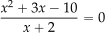
. - Solve for in the expression
 .
.
Show solution/hide solution.
- Distributing the 4, then
 . Adding 8 to both sides gives
  . Finally, dividing both sides by 4, then
  .
. - Removing parentheses and combining like terms gives
 .
. - Distributing the 2 gives
 . Combining like terms gives
  . Subtracting 6 from both sides gives
  . Finally, dividing both sides by 3 gives
  .
. - Distributing the coefficients gives
 . Combining like terms leads to
  .
. - First, notice that the expression is undefined when
 because it would result in a division by zero. So, is not a valid solution. First, factor the numerator to get
![\[ \frac{{(x + 5)(x - 2)}}{{x + 2}} = 0 \]](https://eaglepubs.erau.edu/app/uploads/quicklatex/quicklatex.com-87f3abe02a5b14928a5eff5ab888c756_l3.svg "Rendered by QuickLaTeX.com")
Then, each factor can be set equal to zero, i.e.,
![\[ x + 5 = 0 \mbox{~or~} x - 2 = 0 \]](https://eaglepubs.erau.edu/app/uploads/quicklatex/quicklatex.com-b33df3a6cc6a21a17e65c22afad72fc2_l3.svg "Rendered by QuickLaTeX.com")
Solving each equation separately gives the solution to the original expression as
 and
and  .
.
Calculus
Engineering requires calculus, and in the use of calculus, there is a need to know how to do differentiation and integration. Both processes have rules. Success with calculus means first learning the rules, i.e., the mechanical processes usually taught to engineers by the mathematics department. But to succeed with calculus in engineering means much more, in that the process of doing the mathematics must also be physically interpreted. For example, differentiation is akin to finding a rate of change, a slope, or a gradient, and integration is about finding a sum, such as an area, a volume, or a contribution of something that acts or is distributed along a particular path or area. The tangible application of mathematics within the engineering framework is an acquired skill, but it is a skill essential for success as an engineer.
Ordinary Differentiation
Finding the change in one thing with respect to another is the essence of differentiation. The fundamental rules of differentiation are:
1. Power Rule:
(1) 
2. Constant Rule:
(2) 
3. Sum/Difference Rule:
(3) 
4. Product Rule:
(4) 
5. Quotient Rule:
(5) 
6. Chain Rule:
(6) 
Having laid down these basic rules, which are the first things to learn, they are necessary but insufficient for engineering. Interpreting and understanding the meaning of these processes is more challenging, but it is essential to achieving success in engineering problem-solving. Experienced engineers take these “rules” for granted and do the mathematics valor facialis.[4]
Check Your Understanding #2 – Review problems using differentiation
- Find the derivative of the function
 .
. - Find the derivative of the function
 .
. - Find the derivative of the function

- Find the derivative of the function
 .
. - Find the derivative of the function
 .
.
Show solution/hide solution.
- By taking the derivative term by term, then
![\[ f'(x) = \frac{df}{dx} = 6x + 2 \]](https://eaglepubs.erau.edu/app/uploads/quicklatex/quicklatex.com-db63e6a03b6392e01d57ae2d12957864_l3.svg "Rendered by QuickLaTeX.com")
2. Applying the chain rule leads to
![\[ g'(x) = \frac{dg}{dx} = 2\cos 2x - \sin x \]](https://eaglepubs.erau.edu/app/uploads/quicklatex/quicklatex.com-8bda4e28e0daf19413cc4d5fe36b8e8c_l3.svg "Rendered by QuickLaTeX.com")
3. Using the power rule gives
![\[ h' (x) = \frac{dh}{dx} = -6x^{-4} \]](https://eaglepubs.erau.edu/app/uploads/quicklatex/quicklatex.com-f67151ab88b9fccd9cf42206ce307d6a_l3.svg "Rendered by QuickLaTeX.com")
4. Applying the chain rule gives
![\[ y' (x) = \frac{dy}{dx} = \frac{6x}{3x^2 + 1} \]](https://eaglepubs.erau.edu/app/uploads/quicklatex/quicklatex.com-2d70be3034ecbe3dbc7288af21f4a4b8_l3.svg "Rendered by QuickLaTeX.com")
5. Using the power rule and the chain rule leads to
![\[ f'(x) = \frac{df}{dx} = \frac{3x^2 + 2}{2\sqrt{x^3 + 2x}} \]](https://eaglepubs.erau.edu/app/uploads/quicklatex/quicklatex.com-a483f619e229d5c42bbfc306729a5ea1_l3.svg "Rendered by QuickLaTeX.com")
Partial Differentiation
Partial differentiation is a mathematical operation used to find the rate of change of a multivariable function with respect to one specific variable while keeping all other variables constant. In the context of a function of two variables,  , the partial derivative of
  with respect to is denoted as
  , and this represents the rate of change of with respect to while treating
  as a constant. Similarly, the partial derivative of with respect to is denoted as
  , which represents the rate of change of with respect to while treating as a constant.
In general, to compute a partial derivative, the function is differentiated with respect to the variable of interest, treating all other variables as constants. Partial differentiation is a fundamental tool in calculus. It is extensively used in engineering to analyze how a function changes with respect to specific variables in complex systems with multiple independent variables or degrees of freedom. Indeed, as will become apparent in later chapters of this book, using partial derivatives in engineering becomes a common practice rather than an exception.
Check Your Understanding #3 – Review problems using partial derivatives
For each of the following functions, compute  and
and  :
:

Show solution/hide solution.
 . First, differentiate the function with respect to
  while treating
  as a constant, giving
![\[ \frac{\partial f}{\partial x}=4x+3y \]](https://eaglepubs.erau.edu/app/uploads/quicklatex/quicklatex.com-7147807c66456e63bae925da69ed849b_l3.svg "Rendered by QuickLaTeX.com")
Next, differentiate the function with respect to
while treating as a constant, giving![\[ \frac{\partial f}{\partial y}=3x+2y \]](https://eaglepubs.erau.edu/app/uploads/quicklatex/quicklatex.com-bb4babdde8830afb94394dbf98af3b5b_l3.svg "Rendered by QuickLaTeX.com")
 . First, differentiate with respect to (treat as constant), i.e.,
![\[ \frac{\partial f}{\partial x}=12x^{2}y+5 \]](https://eaglepubs.erau.edu/app/uploads/quicklatex/quicklatex.com-b7d70adac0ed608d1dff7fe05fd3267f_l3.svg "Rendered by QuickLaTeX.com")
Next, differentiate with respect to
(treat as constant), i.e.,![\[ \frac{\partial f}{\partial y}=4x^{3}-4y^{3} \]](https://eaglepubs.erau.edu/app/uploads/quicklatex/quicklatex.com-57bee15f06993f8f6070f5111099d38e_l3.svg "Rendered by QuickLaTeX.com")
 . First, differentiate with respect to (use the chain rule), i.e.,
![\[ \frac{\partial f}{\partial x} =\frac{1}{x^{2}+y^{2}}\, 2x =\frac{2x}{x^{2}+y^{2}} \]](https://eaglepubs.erau.edu/app/uploads/quicklatex/quicklatex.com-c39ca76e4557b08ea5e27e8e69e167bf_l3.svg "Rendered by QuickLaTeX.com")
Next, differentiate with respect to
(again using the chain rule), i.e.,![\[ \frac{\partial f}{\partial y} =\frac{1}{x^{2}+y^{2}}\, 2y =\frac{2y}{x^{2}+y^{2}} \]](https://eaglepubs.erau.edu/app/uploads/quicklatex/quicklatex.com-c51de8ebc12692ff4d99300db1fc9190_l3.svg "Rendered by QuickLaTeX.com")
 . First, differentiate with respect to (treat as constant and apply the chain rule to
  ), i.e.,
![\[ \frac{\partial f}{\partial x} =\left(y\,e^{xy}\right)\sin y =y\,e^{xy}\sin y \]](https://eaglepubs.erau.edu/app/uploads/quicklatex/quicklatex.com-89395694a8e2c59fbef0c4865ee35bea_l3.svg "Rendered by QuickLaTeX.com")
Next, differentiate with respect to
(product‐and chain‐rule on  ), i.e.,
![\[ \frac{\partial f}{\partial y} =\left(xe^{xy}\right)\sin y + e^{xy}\cos y =xe^{xy}\sin y + e^{xy}\cos y \]](https://eaglepubs.erau.edu/app/uploads/quicklatex/quicklatex.com-99a67ffe58d2e3b9f1ed291b6b05b491_l3.svg "Rendered by QuickLaTeX.com")
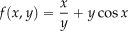 . First, differentiate with respect to (treat as constant), i.e.,
![\[ \frac{\partial f}{\partial x} =\frac{1}{y} - y\sin x \]](https://eaglepubs.erau.edu/app/uploads/quicklatex/quicklatex.com-559b635edef34c657ccdf0f8f4a9e030_l3.svg "Rendered by QuickLaTeX.com")
Next, differentiate with respect to
(treat as constant), i.e.,![\[ \frac{\partial f}{\partial y} =-\frac{x}{y^{2}} + \cos x \]](https://eaglepubs.erau.edu/app/uploads/quicklatex/quicklatex.com-46bd1e92ed92a308bc663c44b637e3dd_l3.svg "Rendered by QuickLaTeX.com")
Integration
Integration is a process often explained as the opposite of differentiation, i.e., the inverse of differentiation. Integration is more complex than differentiation, but it comes up in some form in most engineering problem-solving. Integration techniques involve using the power rule, trigonometric and logarithmic integrals, and the substitution method. Most engineers only recall some of the rules of integration; after all, they aspire to be more than just pure mathematicians. Still, they can look them up as standard integrals in books, or now they can be solved online using artificial intelligence (AI) tools such as Wolfram Alpha or ChatGPT. The ability to successfully use calculus should never be guesswork. Labora callide, non fortiter.[5]
The fundamental rules of integration are:
1. Power Rule:
(7) 
2. Constant Multiple Rule:
(8) 
3. Sum/Difference Rule:
(9) 
4. Integration by Parts:
(10) 
5. Substitution Rule:
(11) 
Again, the rules are the first things to learn, but the meaning of the integration processes must also be understood in engineering.
Check Your Understanding #4 – Review problems using integration
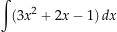
- Evaluate the integral
 .
. - Evaluate the integral
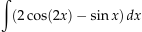 .
. - Evaluate the integral
 .
. - Evaluate the integral
 .
. - Evaluate the integral
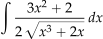 .
.
Show solution/hide solution.
1. Integrating term by term gives
![\[ \int (3x^2 + 2x - 1) \, dx = \dfrac{3}{3}x^3 + \dfrac{2}{2} x^2 - x + c = x^3 + x^2 - x + c \]](https://eaglepubs.erau.edu/app/uploads/quicklatex/quicklatex.com-bba002587fc85b749adf13264b9f25eb_l3.svg "Rendered by QuickLaTeX.com")
where  is the constant of integration.
2. Integrating each term separately leads to
![\[ \begin{aligned} \int\!\left(2\cos(2x)-\sin x\right)\, dx &= 2\int \cos(2x)\,dx - \int \sin x\,dx \\[6pt] &= 2\left(\frac{\sin(2x)}{2}\right) - (-\cos x) + c \\[6pt] &= \sin(2x) + \cos x + c \end{aligned} \]](https://eaglepubs.erau.edu/app/uploads/quicklatex/quicklatex.com-80185a20b52925e79978eec99b485e19_l3.svg "Rendered by QuickLaTeX.com")
where is the constant of integration.
3. Applying the power rule of integration gives
![\[ \displaystyle{\int -6x^{-4}} \, dx = 2x^{-3} + c \]](https://eaglepubs.erau.edu/app/uploads/quicklatex/quicklatex.com-651b01bb9bcbd5719f4e9191b76ec838_l3.svg "Rendered by QuickLaTeX.com")
where is the constant of integration.
4. Using the substitution  , then
  and the integral becomes
![\[ \displaystyle \int \dfrac{6x}{3x^2 + 1}\, dx = \int \dfrac{du}{u} = \ln|u| + c \]](https://eaglepubs.erau.edu/app/uploads/quicklatex/quicklatex.com-006ea366aeb31fb985d33655a30554d4_l3.svg "Rendered by QuickLaTeX.com")
where is the constant of integration. By substituting back , the final result is
![\[ \int \dfrac{6x}{3x^2 + 1}\, dx = \ln \bigl| \, 3x^2 + 1\,\bigr| + c \]](https://eaglepubs.erau.edu/app/uploads/quicklatex/quicklatex.com-b132a985d953091470114808df318d44_l3.svg "Rendered by QuickLaTeX.com")
5. The integral to be solved is
![\[ \int \dfrac{3x^{2}+2}{2\sqrt{x^{3}+2x}} \, dx \]](https://eaglepubs.erau.edu/app/uploads/quicklatex/quicklatex.com-a2de944b0446ebadd5478db6f13c64ed_l3.svg "Rendered by QuickLaTeX.com")
Let  so
so  . Therefore,
![\[ \int \dfrac{3x^{2}+2}{2\sqrt{x^{3}+2x}} \, dx = \frac12 \int u^{-1/2}\, du = u^{1/2} + c = \sqrt{x^{3}+2x} + c \]](https://eaglepubs.erau.edu/app/uploads/quicklatex/quicklatex.com-3ac99d25e7d755d150c02238ece372cb_l3.svg "Rendered by QuickLaTeX.com")
where is the constant of integration.
Working with Vectors
A vector is like a direction, force, or something else that has both magnitude and direction. Vectors come up everywhere in engineering. Si vectores nescis, tunc errabis. Vectors are represented by arrows with a length proportional to the magnitude, and the orientation denotes the direction. Vectors are also used to indicate a specific location in space, known as a position vector. The location of an arbitrary point in space, say P, can be defined by specifying the values of three coordinates, i.e., in terms of  in a standard Cartesian coordinate system. As shown in the figure below, the point P can be located by the position vector,
  , where
(12) 
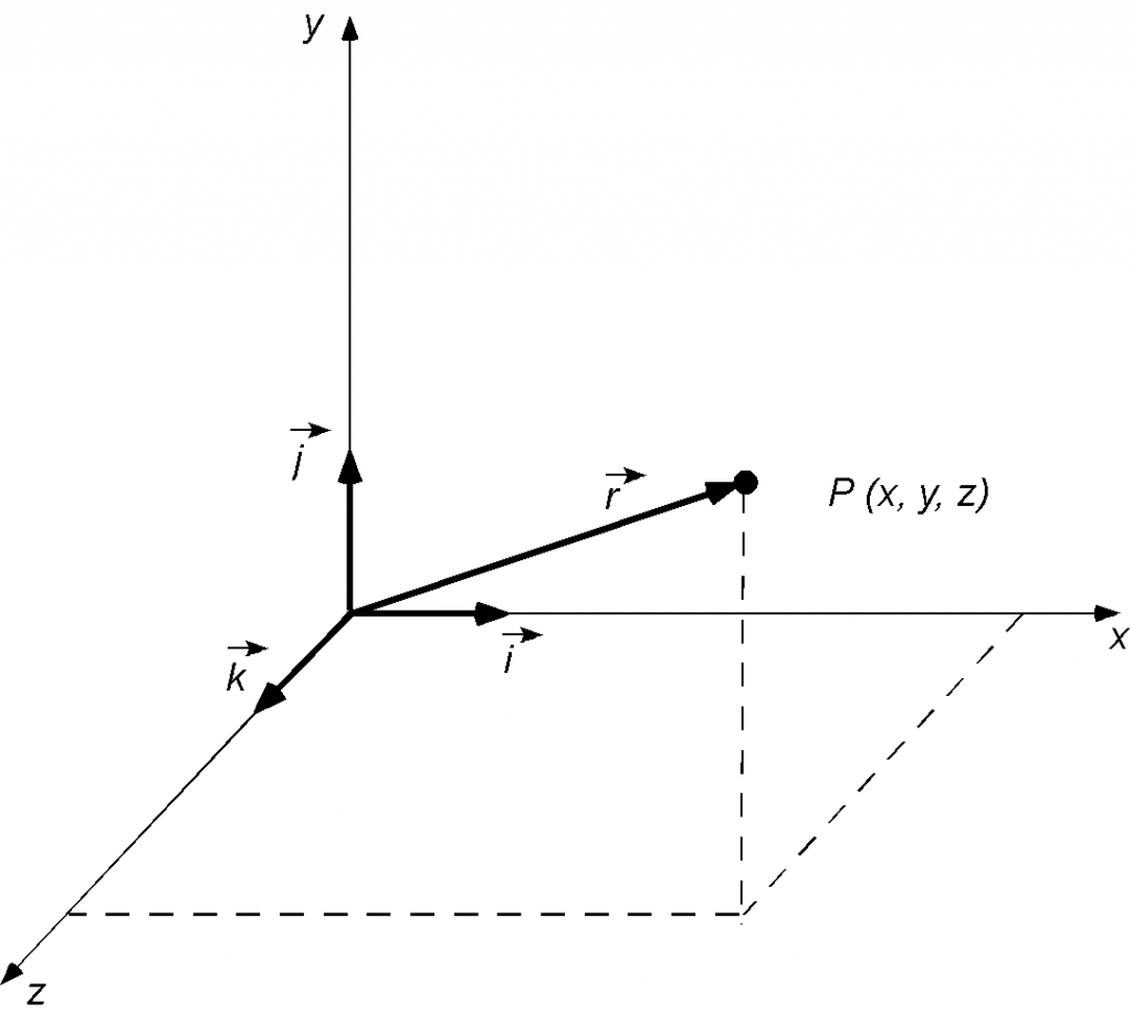 in a Cartesian coordinate system.
In general, if  is a given vector in a Cartesian coordinate system and
  , and
, and  are the components of in the
  and
and  directions, then
(13) 
as shown in the figure below.
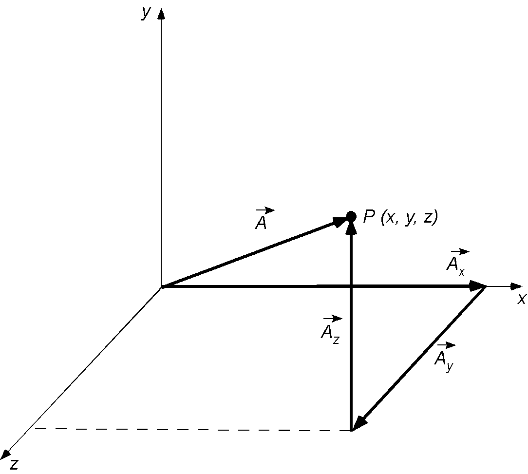
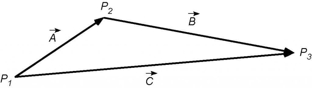
Vectors can represent velocities (a speed in a given direction), forces, accelerations, or other quantities. Vectors can be added to find the total effect (such as total velocity, force, or acceleration) by adding components component-by-component, nose-to-tail. If is directed from point P_1 to point P_2 and a second vector  is defined as
(14) 
that points from P_2 to P_3, then the resultant vector  that points from P_1 to P_3 is
(15) 
Alternative coordinate systems can be used to describe any problem; for example, a cylindrical or spherical coordinate system can be used instead of a Cartesian one. Typically, selecting a suitable coordinate system is a matter of convenience. Still, it is also important to determine whether the mathematics can be appropriately simplified in an alternative coordinate system. For example, in introductory engineering problems, Cartesian coordinate systems are used primarily; however, polar coordinates are sometimes used when convenient. It is best to start with Cartesian coordinates to understand the rules of mathematics.
Scalar and Vector Fields
A scalar quantity given as a function of coordinate space  (and perhaps time
  ) is called a scalar field. For example, fluid properties such as pressure
  , density
  , and temperature
  are all scalar quantities, i.e.,
(16) ![\begin{eqnarray*} p & = & p\left( x, y,z \right) \\[6pt] \varrho & = & \varrho\left( x, y, z \right) \\[6pt] T & = & T\left( x, y, z \right) \end{eqnarray*}](https://eaglepubs.erau.edu/app/uploads/quicklatex/quicklatex.com-5c81b21770b201675882b2414ac04d57_l3.svg "Rendered by QuickLaTeX.com")
Similarly, a vector quantity given as a function of coordinate space and time is called a vector field. e.g., velocity is a vector quantity. A velocity can be written in terms of its scalar components, i.e.,
(17) 
where the components are
(18) ![\begin{eqnarray*} V_{x} & = & V_{x} \left( x, y, z \right) \\[6pt] V_{y} & = & V_{y} \left( x, y, z \right) \\[6pt] V_{z} & = & V_{z} \left( x, y, z \right) \end{eqnarray*}](https://eaglepubs.erau.edu/app/uploads/quicklatex/quicklatex.com-813b739a85f0d9433b4569a61f2d3e36_l3.svg "Rendered by QuickLaTeX.com")
More often than not, the velocity vector is written as
(19) 
where  ,
,  and
and  are the components in the , and direction, respectively.
Similar expressions can be written for cylindrical and spherical coordinates. In many theoretical aerodynamic and other engineering problems, various scalar and vector fields are unknowns that must subsequently be determined in a solution with prescribed initial and boundary conditions.
Scalar Products
Let the vectors and be given by
(20) ![\begin{eqnarray*} \vec{A} & = & A_{x}\, \vec{i} + A_{y}\, \vec{j} + A_{z} \, \vec{k} \\[6pt] \vec{B} & = & B_{x}\, \vec{i} + B_{y}\, \vec{j} + B_{z} \, \vec{k} \end{eqnarray*}](https://eaglepubs.erau.edu/app/uploads/quicklatex/quicklatex.com-078b1fe94cc75cd347a7a73b7e2fd881_l3.svg "Rendered by QuickLaTeX.com")
Then the scalar or “dot” product  or “ dot
  ” is given by
(21) 
Notice that the “centered dot” or “ ” represents the scalar product operator.
As shown in the figure below, physically, the scalar product is the projection of one vector onto another, i.e., the component of one vector in the direction of the other. For example, the scalar projection (or scalar component) of a vector in the direction of a vector is given by
(22) 
where  is the angle between the vectors
  and
and  .
.
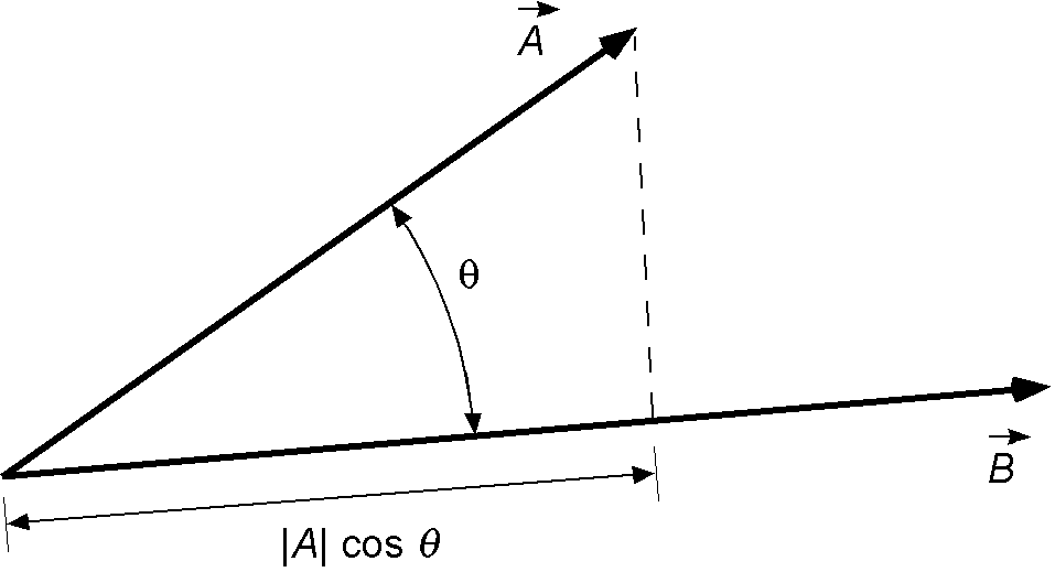
Notice that because  is the projection of onto , then
  is equal to the projection of onto times the magnitude of . Similarly, because
  is the projection of onto , then also equals the projection of onto times the magnitude of . However, the easiest way to remember what the dot product means is just
  .
.
Vector Products
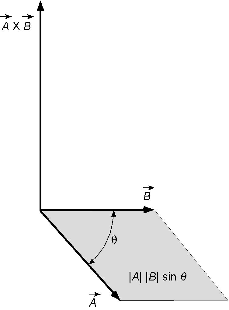
The vector product  (cross product) is given by
(23) 
where the vector product or “cross product” is denoted by the  operator, is the angle between the two vectors, and
  is a unit vector perpendicular to the plane containing the two vectors, as shown in the figure below. Notice that the cross-product is also the area of the shaded parallelogram. Similar to the dot or scalar product, the concept of a cross-product has numerous applications in engineering.
In general, the vector product can also be written as
(24) ![\begin{equation*} \vec{A} \times \vec{B} = \left| \begin{array}{ccc} \, \vec{i} & \, \vec{j} & \, \vec{k} \\[6pt] A_x & A_y & A_z \\[6pt] B_x & B_y & B_z \end{array} \right| \end{equation*}](https://eaglepubs.erau.edu/app/uploads/quicklatex/quicklatex.com-86163af2f965728dc8fd2f1ceb47efbf_l3.svg "Rendered by QuickLaTeX.com")
Expanding this operation out in terms of the third-order determinant gives
(25) 
Similar expressions for  and
and  can be written in cylindrical and spherical coordinate systems.
Vector Projections
Vector projections isolate the part of one vector that lies along another, a step that recurs whenever quantities must be decomposed into parallel and perpendicular components. They appear, for example, in calculating mechanical work, where only the force component along the displacement contributes. They also occur in many other contexts in aerospace engineering, including structural analysis, where loads are split into axial and shear parts.
The dot product of two vectors is a scalar, i.e.,
(26) 
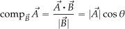
However, the scalar projection (component) of onto is
(27) 
In a similar manner, the vector projection of onto is
(28) 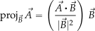
Therefore, the dot product supplies the scalar factor , and dividing by  or
or  (and multiplying by
  for the vector form) isolates the part of
  that lies along .
Check Your Understanding #5 – Review problems with vector operations
Given two vectors  and
and  , then evaluate:
-
 .
. .
. .
.- The angle between and .
- The projection of onto .
Show solution/hide solution.
- Multiply by 3 and subtract from , i.e.,
![\[ \vec{A}-3\vec{B} =(-3\,\vec{i}+2\,\vec{j})-3(5\,\vec{i}-2\,\vec{j}) =(-3\,\vec{i}+2\,\vec{j})-(15\,\vec{i}-6\,\vec{j}) =-18\,\vec{i}+8\,\vec{j} \]](https://eaglepubs.erau.edu/app/uploads/quicklatex/quicklatex.com-3a11353c7626219e212f850d04f167c0_l3.svg "Rendered by QuickLaTeX.com")
Notice that the result is a vector.
- Take the dot product of matching components, i.e.,
![\[ \vec{A} \bigcdot \vec{B} = (-3 \, \vec{i} + 2 \, \vec{j} ) \bigcdot ( 5 \, \vec{i} - 2 \, \vec{j} ) = (-3)(5) + (2)(-2) = -15 - 4 = -19 \]](https://eaglepubs.erau.edu/app/uploads/quicklatex/quicklatex.com-1dc163b14f93000037164eb588045276_l3.svg "Rendered by QuickLaTeX.com")
Notice that the result is a scalar.
- Form the determinant (treating the
 ‐components as zero), i.e.,
![\[ \vec{A}\times\vec{B} =\begin{vmatrix} \vec{i} & \vec{j} & \vec{k} \ \\ -3 & 2 & 0 \ \\ 5 & -2 & 0 \ \end{vmatrix} = (-3)(-2) - (5)(2) = 6 - 10 = -4\,\vec{k} \]](https://eaglepubs.erau.edu/app/uploads/quicklatex/quicklatex.com-0a70db7c4ed49a2696be0df75d780452_l3.svg "Rendered by QuickLaTeX.com")
- Find the angle between the vectors using
 . The magnitudes of the vectors are
![\[ |\vec{A}|=\sqrt{(-3)^2+2^2}=\sqrt{13} \quad \text{and} \quad |\vec{B}|=\sqrt{5^2+(-2)^2}=\sqrt{29} \]](https://eaglepubs.erau.edu/app/uploads/quicklatex/quicklatex.com-205552f723e54aa766572bb7d55193c8_l3.svg "Rendered by QuickLaTeX.com")
so that
![\[ \cos\theta =\frac{-19}{\sqrt{13}\,\sqrt{29}} =\frac{-19}{\sqrt{377}} \quad \text{and} \quad \theta=\arccos \left(-\frac{19}{\sqrt{377}}\right) = 168.1^{\circ} \]](https://eaglepubs.erau.edu/app/uploads/quicklatex/quicklatex.com-73efd9914a8db5a4db77e2a9e9674f3a_l3.svg "Rendered by QuickLaTeX.com")
- Project onto using
![\[ \displaystyle \operatorname{proj}_{\vec{B}}\vec{A} =\frac{\vec{A} \bigcdot \vec{B}}{|\vec{B}|^{2}}\, \vec{B} \]](https://eaglepubs.erau.edu/app/uploads/quicklatex/quicklatex.com-208b417c1477245b909cbc3007d88627_l3.svg "Rendered by QuickLaTeX.com")
Therefore,
![\[ |\vec{B}|^{2} = 29 \quad \text{and} \quad \operatorname{proj}_{\vec{B}}\vec{A} =\frac{-19}{29}\, \left( 5\,\vec{i} -2\,\vec{j} \right) = -\frac{95}{29}\,\vec{i} + \frac{38}{29}\,\vec{j} \]](https://eaglepubs.erau.edu/app/uploads/quicklatex/quicklatex.com-1668369f1e1c5578041422d32d2867d9_l3.svg "Rendered by QuickLaTeX.com")
Differentiating a Vector
To differentiate a vector, it must depend on time, i.e., its magnitude and/or direction change over time. Therefore, the derivative of the vector will be its time rate of change. For example, let the vector be  , a position in space. The time derivative of will be a velocity, i.e.,
(29) 
Therefore, the derivative of a vector is a vector.
In other possible engineering examples, if were the momentum of something, then the time rate of change of momentum would be a force. If the parameter were velocity, then the time rate of change of velocity is acceleration. If the parameter were to be the quantity of work, then the time derivative would be power. Therefore, differentiating a vector can lead to valuable outcomes for engineering applications.
Check Your Understanding #6 – Differentiating a vector
Differentiate each of the following vector functions:



Show solution/hide solution.



Line Integrals
Consider a vector field  . Also, consider a curve in space connecting two points
  and
and  , as shown in the figure below. Let
  be an elemental length of the curve.
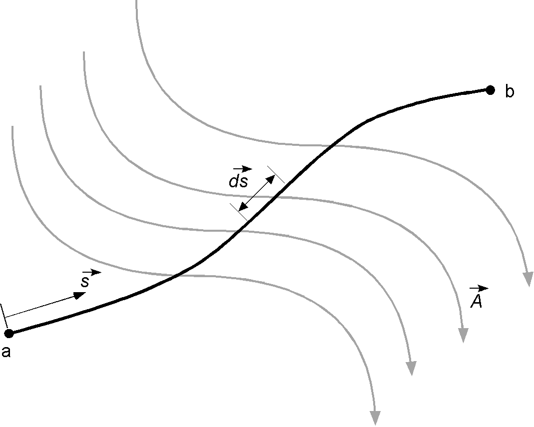
The line integral along the curve from to is
(30) 
which is simply a statement that the integral is the sum of the components of the vector field along the direction of the curve to .
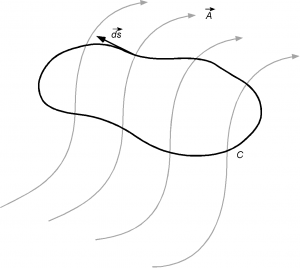
If the curve is closed, i.e., points and are coincident, then the line integral is
(31) 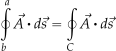
where the counterclockwise direction is considered positive according to the convention used in the field of mathematics, as shown in the figure below.
Check Your Understanding #7 – Line Integrals
Evaluate each of the following line integrals:
 along the straight-line segment from (0, 0) to (2, 4).
 along the quarter-circle arc of radius 1 from (1, 0) to (0, 1) in the first quadrant.
 along the straight-line segment from (0, 0) to (1, 1).
Show solution/hide solution.
- First, parameterise the line by
 with
with  . Then
![\[ \left( \frac{dx}{dt}\right)^{2}+ \left( \frac{dy}{dt} \right)^{2} = 1^{2}+2^{2} = 5 \]](https://eaglepubs.erau.edu/app/uploads/quicklatex/quicklatex.com-b96adc5f9cbfd418b0495a4f7e357c16_l3.svg "Rendered by QuickLaTeX.com")
so
 , and
, and![\[ \int_{C}(x^{2}+y)\,ds=\int_{0}^{1}\left( t^{2} + 2t \right)\sqrt5\,dt=\sqrt5\int_{0}^{1}(t^{2}+2t)\,dt=\sqrt5 \left( \dfrac{1}{3} t^{3}+t^{2}\right)_{0}^{1}=\dfrac{4}{3} \sqrt5 \]](https://eaglepubs.erau.edu/app/uploads/quicklatex/quicklatex.com-10234f0fe60a5108bc0c1708f6c39e0b_l3.svg "Rendered by QuickLaTeX.com")
- Parameterise the quarter-circle using
 and
and  with
with  . Notice that
  because
  and so
![\[ \int_{C}(x+y^{2})\,ds=\int_{0}^{\pi/2} \left( \cos\theta+\sin^{2}\theta \right)\,d\theta=\left[ \sin\theta+\dfrac{1}{2}\theta-\dfrac{1}{4}\sin2\theta \right]_{0}^{\pi/2}=1+\frac{\pi}{4} \]](https://eaglepubs.erau.edu/app/uploads/quicklatex/quicklatex.com-b93d966b48fbb89e361625a40108cc62_l3.svg "Rendered by QuickLaTeX.com")
- Parameterise the line using
 with
with  . Then
![\[ ds=\sqrt{(dx/dt)^{2} + (dy/dt)^{2}}\ dt=\sqrt{1 + 1}\,dt=\sqrt2\,dt \]](https://eaglepubs.erau.edu/app/uploads/quicklatex/quicklatex.com-9446fadc112c0e6c22001629b134e43d_l3.svg "Rendered by QuickLaTeX.com")
The integrand becomes
 , so that
![\[ \int_{C}x^{2}y\,ds=\sqrt2\int_{0}^{1}t^{3}\,dt=\sqrt2 \left[ \dfrac{1}{4} t^{4}\right]_{0}^{1}=\frac{\sqrt2}{4} \]](https://eaglepubs.erau.edu/app/uploads/quicklatex/quicklatex.com-428c55ecc2ed945ba9783f3648d9870a_l3.svg "Rendered by QuickLaTeX.com")
Surface Integrals
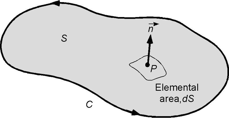
Consider now a surface  bounded by a curve
  , as shown in the figure below. Let
  be an elemental surface area and let be a unit normal vector, i.e., one perpendicular to the surface. Let be a scalar field in this space and a vector field. A surface integral over the surface can be defined as
(32) 
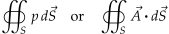
where  is called the elemental vector area or the unit normal vector area. If the surface is closed, then the integral is written as
(33) 
Line integrals can also be based on scalar functions, e.g., the scalar  integrated along a curve given by
![\[\int_C \, p (x, y) \, ds \]](https://eaglepubs.erau.edu/app/uploads/quicklatex/quicklatex.com-38c2510f68444e5c5c783ecec3c16f8a_l3.svg "Rendered by QuickLaTeX.com")
where represents an infinitesimal length along the curve .
Unit Normal Vector
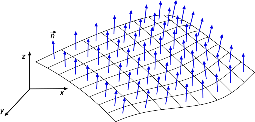
The meaning of a unit normal vector, also known as a normal unit vector or simply a normal vector, should be understood because it comes up in many engineering problems. The unit normal is a vector perpendicular (or orthogonal) to a surface at a particular point. It has a magnitude of 1, hence the term “unit.” The normal vector always points away from the surface perpendicularly, as shown in the figure below.
The unit normal vector is often denoted by the symbol . For a surface defined by a function  , where are the coordinates of a point on the surface, then the unit normal vector at that point can be obtained by taking the gradient of the function and normalizing it, as given by
(34) 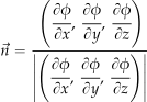
where  denotes the Euclidean L2 norm or magnitude of the vector. By normalizing the gradient vector, the resulting unit normal vector will have a magnitude of 1. This normalization is achieved by dividing the gradient vector by its magnitude.
Different methods exist to find the unit normal from discrete surface points, such as the cross-product approach or the least-squares fitting procedure. The cross-product approach is the easiest. The steps are:
- Select three neighboring points on the surface defined by the vectors
 ,
,  and
and  .
. - Calculate the vectors between these points, i.e.,
 and
and  .
. - Compute the cross product of these vectors giving
 .
. - Normalize the resulting vector to obtain the unit normal vector, i.e.,
 .
.
Remember that the unit normal vector is a crucial concept in vector calculus, used in various mathematical and physical applications, such as determining the direction of a force on a surface and solving problems involving surface integrals or differential equations.
Check Your Understanding #8 – Calculating unit normal vectors
- In a three-dimensional Cartesian coordinate system, what is the unit normal vector for the direction of the x-axis?
- Consider a two-dimensional plane defined by
 . What is the unit normal to this plane?
 - Consider a three-dimensional plane defined by
 . What is the unit normal to this plane?
Show solution/hide solution.
- This vector is parallel to the -axis and points in the positive -direction, so
 .
. - In this case,
 . Therefore, at any point on this plane, the unit normal vector will be
![\[ \vec{n} = \cfrac{ \left( \displaystyle{\cfrac{\partial \phi}{\partial x}}, \, \displaystyle{\cfrac{\partial \phi}{ \partial y}}, \, \displaystyle{\cfrac{\partial \phi}{ \partial z}} \right) }{ \left| \left( \displaystyle{\cfrac{\partial \phi}{ \partial x}}, \, \displaystyle{\cfrac{\partial \phi}{ \partial y}}, \, \displaystyle{\cfrac{\partial \phi}{ \partial z}} \right) \right| } = \cfrac{ (1, 1, 0)}{\sqrt{2}} = \left( \cfrac{1}{\sqrt{2}}, \, \cfrac{1}{\sqrt{2}}, \, 0 \right) \]](https://eaglepubs.erau.edu/app/uploads/quicklatex/quicklatex.com-d778a7f706a7fcb4729daf3cfe588132_l3.svg "Rendered by QuickLaTeX.com")
- In this final case,
 . Therefore, at any point on this plane, the unit normal vector will be
![\[ \vec{n} = \cfrac{(2, -3, 1)}{\sqrt{14}} = \left(\cfrac{2}{\sqrt{14}}, \, \cfrac{-3}{\sqrt{14}}, \, \cfrac{1}{\sqrt{14}} \right) \]](https://eaglepubs.erau.edu/app/uploads/quicklatex/quicklatex.com-b2993d2312119e7eff9e3a65d3fe6346_l3.svg "Rendered by QuickLaTeX.com")
Volume Integrals
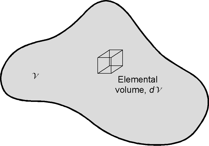
Consider a volume  in space, as shown in the figure below, which contains a small elemental volume
  . Let be a scalar field in this space. The volume integral over the volume of the quantity is written as
(35) 
The result of the integration is a scalar.
If  is a vector field in space, then the volume integral is written as
(36) 
and the result in this latter case will be a vector. If  , then the volume integral of over a region is evaluated using
(37) 
which is a vector representing the accumulated effect of the vector field throughout the entire volume.
Check Your Understanding #9 – Volume integrals
- Evaluate the volume integral that gives the volume of a solid sphere of radius
 , i.e.,
![\[ {\cal{V}} = \iiint_{\rm sphere} d{\cal{V}} \]](https://eaglepubs.erau.edu/app/uploads/quicklatex/quicklatex.com-a15bfcd25fd158e6e406d794c45b3913_l3.svg "Rendered by QuickLaTeX.com")
where the sphere’s domain is
 .
. - A right circular cone of height
 and base radius has a density that varies linearly with height according to
![\[ \rho(z) = \rho_{0}\,\frac{z}{H}, \qquad 0\le z\le H \]](https://eaglepubs.erau.edu/app/uploads/quicklatex/quicklatex.com-933b726fc073aa05c063f5cf070d7a43_l3.svg "Rendered by QuickLaTeX.com")
Set up and evaluate the volume integral for the total mass, i.e.,
![\[ M = \iiint_{\text{cone}} \rho(z)\,d{\cal{V}} \]](https://eaglepubs.erau.edu/app/uploads/quicklatex/quicklatex.com-546bcb9a30765cfdc2e70a0698bef23f_l3.svg "Rendered by QuickLaTeX.com")
Show solution/hide solution.
- Using spherical coordinates
 with
with ![r\in[0,R]](https://eaglepubs.erau.edu/app/uploads/quicklatex/quicklatex.com-994ea1531246a50f4a0bbc4c27a6c4e5_l3.svg "Rendered by QuickLaTeX.com") ,
, ![\theta\in[0,\pi]](https://eaglepubs.erau.edu/app/uploads/quicklatex/quicklatex.com-848d5a5865c7c36095c13d2c38e3a9aa_l3.svg "Rendered by QuickLaTeX.com") , and
, and ![\phi\in[0,2\pi]](https://eaglepubs.erau.edu/app/uploads/quicklatex/quicklatex.com-3e9ac3a2298fd32b98e01582e748a266_l3.svg "Rendered by QuickLaTeX.com") , then
, then
![\[ {\cal{V}} = \iiint_{\rm sphere} d{\cal{V}} = \int_{0}^{2\pi}\!\!\int_{0}^{\pi}\!\!\int_{0}^{R} r^{2}\sin\theta \, dr\,d\theta\,d\phi = \frac{4}{3}\pi R^{3} \]](https://eaglepubs.erau.edu/app/uploads/quicklatex/quicklatex.com-aad14386d606bd6f21a5bba758090e5d_l3.svg "Rendered by QuickLaTeX.com")
- In cylindrical coordinates
 the cone is given by
  and
and  . The mass integral is
![\[ M = \iiint_{\text{cone}} \rho_{0}\,\frac{z}{H}\,dV = \rho_{0}\!\!\int_{0}^{H}\!\!\int_{0}^{2\pi}\!\!\int_{0}^{(R/H)z} \frac{z}{H}\, r \, dr\,d\phi\,dz \]](https://eaglepubs.erau.edu/app/uploads/quicklatex/quicklatex.com-747cf78c60079872738e2a463df6772a_l3.svg "Rendered by QuickLaTeX.com")
Carrying out the integrations gives
![\[ M = \rho_{0}\! \int_{0}^{H}\!\! \left( \frac{z}{H}\, \frac{1}{2}\Bigl(\tfrac{R}{H}z\Bigr)^{2} \right) 2\pi\, dz = \rho_{0}\,\frac{\pi R^{2} H}{4} \]](https://eaglepubs.erau.edu/app/uploads/quicklatex/quicklatex.com-0c15d51adfd2cd97400a92d4e88a5149_l3.svg "Rendered by QuickLaTeX.com")
Integral Relations
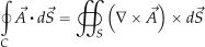
The need to know some important relations between line, surface, and volume integrals occasionally arises when solving engineering problems. Consider an area bounded by a closed curve . Let be a vector field. The line integral of over is related to the surface integral of over by using Stokes’ Theorem, i.e.,
(38) 
Again, consider the volume  enclosed by the closed surface . Then, the surface and volume integrals of the vector field
  are related by using Gauss’s divergence theorem, i.e.,
(39) 
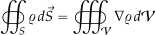
which connects a volume integral to a surface integral. Finally, if represents a scalar field, then the gradient theorem states that
(40) 
Gradient of a Scalar Field
If  , then the gradient
  (or grad ) is given by
(41) 
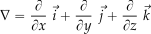
where the operator  (which is called nabla or del) is defined as
(42) 
Physically, is the normal to the surface defined by  = constant, as illustrated in the figure below.
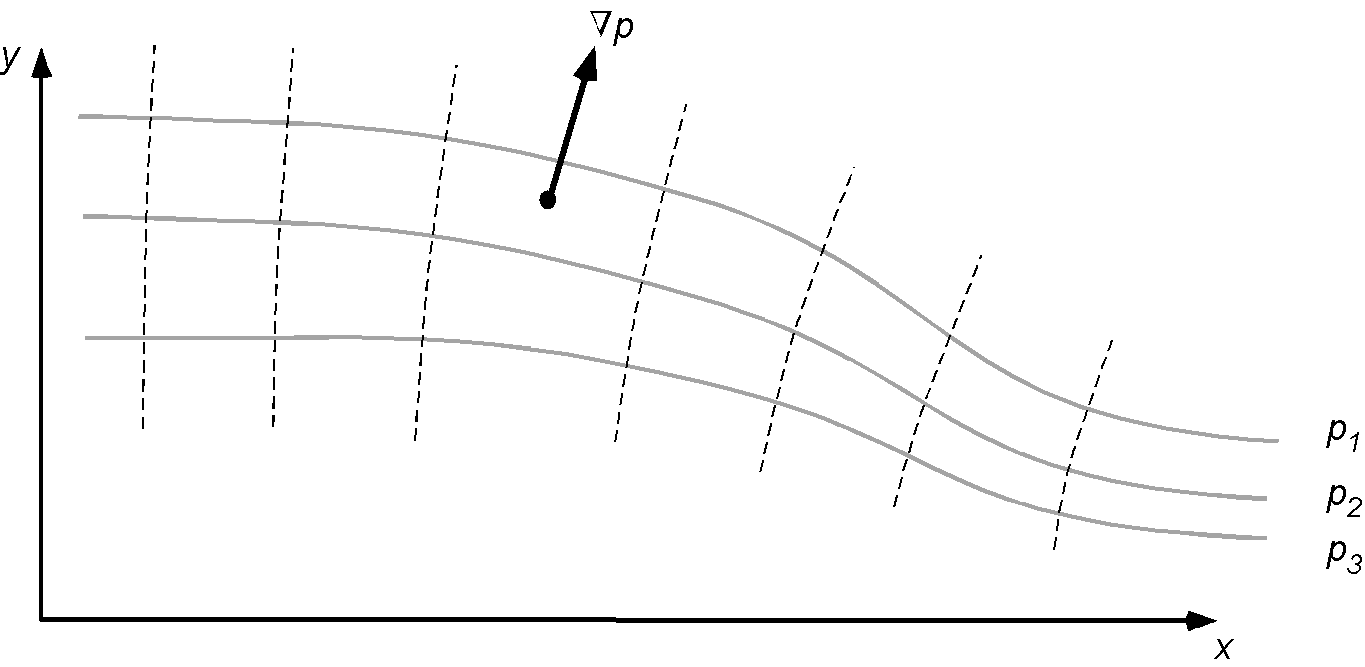
Related to the gradient is the concept of a directional derivative. Consider some scalar quantity  defined at some point over a surface. Choose some arbitrary direction
  away from the point and let be a unit vector in that direction. The rate of change of per unit length in the direction is
(43) 
The directional derivative is the term  . Therefore, it can be appreciated that the rate of change of in any arbitrary direction is simply the component of in that particular direction.
Check Your Understanding #10 – Gradient of a scalar field
A two-dimensional pressure field is given by  . If an isobar is a constant pressure line, plot the isobars for = 0, 2, 4, 6, and 8.
Show solution/hide solution.
The equations of the isobars are
![\begin{eqnarray*} 0 & = & -2x - y + 10 \implies y = -2x + 10 \\[6pt] 2 & = & -2x - y + 10 \implies y = -2x + 8 \\[6pt] 4 & = & -2x - y + 10 \implies y = -2x + 6 \\[6pt] 6 & = &-2x - y + 10 \implies y = -2x + 4 \\[6pt] 8 & = & -2x - y + 10 \implies y = -2x + 2 \end{eqnarray*}](https://eaglepubs.erau.edu/app/uploads/quicklatex/quicklatex.com-c9c3fb0bff5d4cbafafc9380a0ef4a12_l3.svg "Rendered by QuickLaTeX.com")
which are all straight lines, as shown in the figure below.
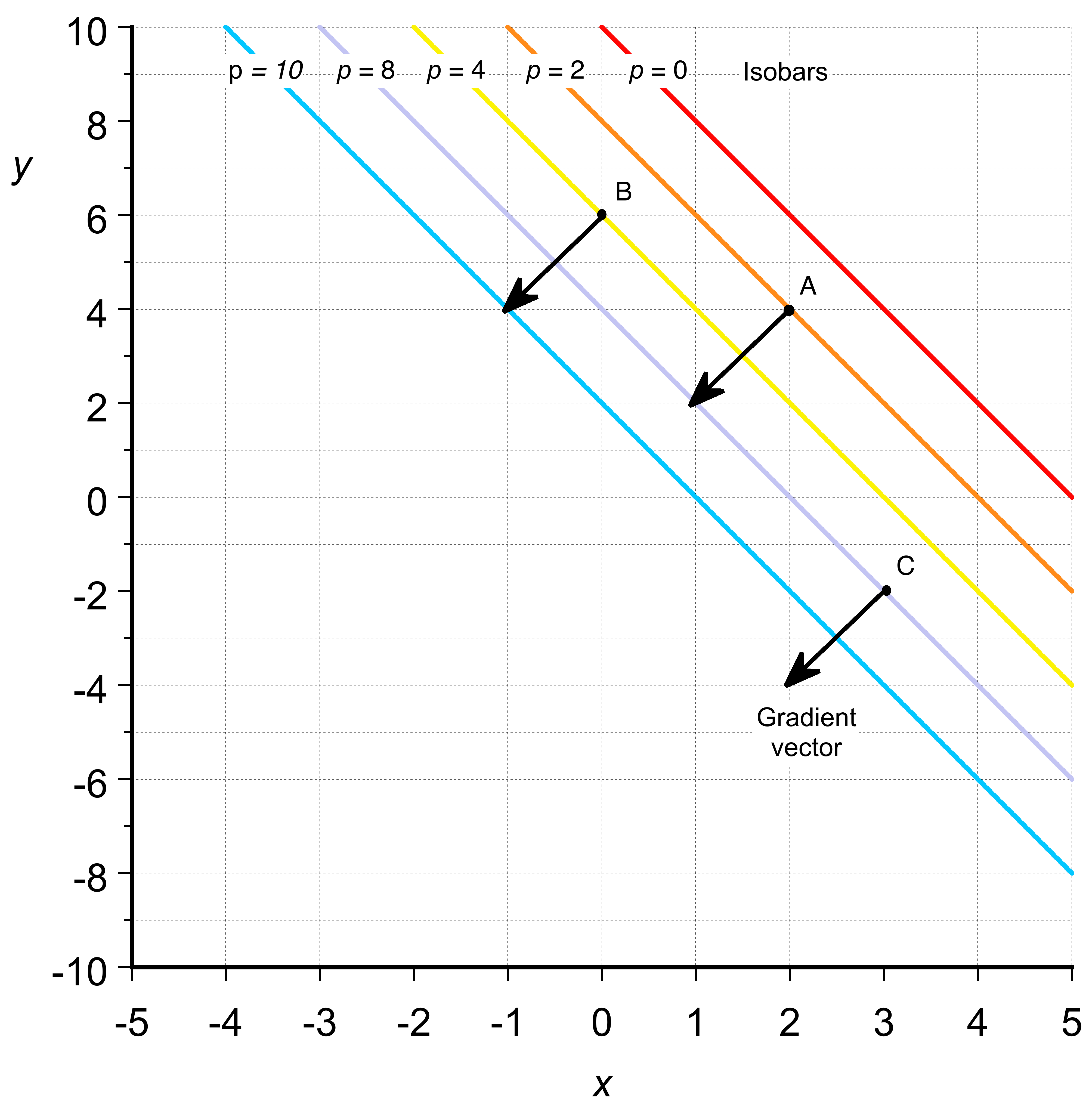 The gradient is given by
![\[ \nabla p = \frac{\partial p}{\partial x} \vec{i} + \frac{\partial p}{\partial y} \vec{j} \]](https://eaglepubs.erau.edu/app/uploads/quicklatex/quicklatex.com-a7c2c45816b36a8698a8245a37657f28_l3.svg "Rendered by QuickLaTeX.com")
so that
![\[ \nabla (-2x - y + 10) = \frac{\partial (-2x - y + 10)}{\partial x} \vec{i} + \frac{\partial (-2x - y + 10)}{\partial y} \vec{j} = -2 \vec{i} - 1 \vec{j} \]](https://eaglepubs.erau.edu/app/uploads/quicklatex/quicklatex.com-98754470e1ff50c6f99a7529d779a030_l3.svg "Rendered by QuickLaTeX.com")
and the magnitude of the pressure gradient is
![\[ | \nabla p | = \sqrt{(-2)^2 + (-1)^2} = \sqrt{5 } = 2.34 \]](https://eaglepubs.erau.edu/app/uploads/quicklatex/quicklatex.com-eaa196f7ccb254a056cfd07d60aa539d_l3.svg "Rendered by QuickLaTeX.com")
The pressure gradient vector represents the magnitude and direction of the pressure change at a specific point in space. It points toward the steepest change in pressure, and its magnitude indicates the rate of pressure change in that direction. In this case, the pressure gradient vector is given by  , which means that the pressure changes most rapidly in the direction , and the rate of decrease is 2 units in the direction and 1 unit in the direction.
To visualize the pressure gradient vectors, they are typically plotted as arrows, with the tail of each arrow placed at a specific point in space. The direction and length of the arrows indicate the direction and magnitude of the pressure gradient at that point. Some arbitrary points can be selected, and then the corresponding pressure gradient vectors are plotted, e.g.,
![\[ \mbox{\small Point A: } (x, y) = (2, 4) \implies \mbox{\small $\nabla p$ at A: } (-2, -1) \]](https://eaglepubs.erau.edu/app/uploads/quicklatex/quicklatex.com-6eb66e800f15e3ea28c16fa0970851d8_l3.svg "Rendered by QuickLaTeX.com")
![\[ \mbox{\small Point B: } (x, y) = (0, 6) \implies \mbox{\small $\nabla p$ at B: } (-2, -1) \]](https://eaglepubs.erau.edu/app/uploads/quicklatex/quicklatex.com-9149c3e6b5a49a2635c475c58342337a_l3.svg "Rendered by QuickLaTeX.com")
![\[ \mbox{\small Point C: } (x, y) = (3, -2) \implies \mbox{\small $\nabla p$ at C: } (-2, -1) \]](https://eaglepubs.erau.edu/app/uploads/quicklatex/quicklatex.com-15ea8936a66e1286dbfdc2895ea7f669_l3.svg "Rendered by QuickLaTeX.com")
Notice that the gradient vector runs perpendicular to the isobars. The pressure gradient vector is the same at each of the points, A, B, and C.
Divergence of a Vector Field
Consider a vector field  , then
(44) ![\begin{eqnarray*} \mbox{div } \vec{V} = \nabla \bigcdot \vec{V} & = & \left(\frac{\partial }{\partial x}\, \vec{i}+\frac{\partial }{\partial y} \, \vec{j}+\frac{\partial }{\partial z}\, \vec{k}\right) \bigcdot \left(V_{x}\, \vec{i}+V_{y}\, \vec{j}+V_{z}\, \vec{k}\right) \nonumber \\[6pt] & = & \frac{\partial V_{x}}{\partial x}+\frac{\partial V_{y}}{\partial y}+\frac{\partial V_{z}}{\partial z} \end{eqnarray*}](https://eaglepubs.erau.edu/app/uploads/quicklatex/quicklatex.com-afb75c37ddf1f0b1082bfe3755d205dc_l3.svg "Rendered by QuickLaTeX.com")
which is a scalar quantity. In aerodynamics and fluid dynamics, the divergence can be interpreted as a flux density or the amount of flux entering or leaving a point in space. Mass fluxes such as  ,
,  , etc., are often used. Divergence is the rate of flux expansion (positive divergence) or contraction (negative divergence). By convention, the flux is defined as positive when it flows out of a closed surface. So, the divergence is just the net flux per unit volume or flux density of the contents of a given region of space.
Curl of a Vector Field
Again, consider the vector field defined by
(45) 
Then the curl of is defined as
(46) ![\begin{equation*} \mbox{curl } \vec{V} \equiv \nabla \times \vec{V} = \left| \begin{array}{ccc} \, \vec{i} &\, \vec{j} & \, \vec{k} \\[6pt] \displaystyle{\frac{\partial}{\partial x}} & \displaystyle{\frac{\partial}{\partial y}} & \displaystyle{\frac{\partial}{\partial z}} \\[10pt] V_x & V_y & V_z \end{array} \right| \end{equation*}](https://eaglepubs.erau.edu/app/uploads/quicklatex/quicklatex.com-90602f982e698229663eff05561ff32e_l3.svg "Rendered by QuickLaTeX.com")
and expanding this determinant gives
(47) 
A physical interpretation of the curl is that it represents the angular velocity of the rotation or “spin” of the contents of a given region of space. In aerodynamics, the curl of a velocity field is referred to as vorticity, a physical concept that helps interpret the behavior of a flow. If the vorticity is zero, the flow is said to be irrotational; if it is non-zero, the flow is rotational.
Check Your Understanding #11 – Finding the curl of a vector field
In a solution to a specific engineering problem, the solution of the vector field  is
is

Find the curl of this field.
Show solution/hide solution.
The curl of a vector requires the evaluation of a determinant, i.e.,
![\[ \nabla \times \vec{A} = \left| \begin{array}{ccc} \, \vec{i} &\, \vec{j} & \, \vec{k} \\[6pt] \displaystyle{\frac{\partial}{\partial x}} & \displaystyle{\frac{\partial}{\partial y}} & \displaystyle{\frac{\partial}{\partial z}} \\[6pt] A_x & A_y & A_z \end{array} \right| \]](https://eaglepubs.erau.edu/app/uploads/quicklatex/quicklatex.com-451a926c607bae23d8f245ba31fdb812_l3.svg "Rendered by QuickLaTeX.com")
Evaluating this determinant gives
![\[ \nabla \times \vec{A} = \left( \frac{\partial A_{z}}{\partial y} - \frac{\partial A_{y}}{\partial z} \right) \, \vec{i} + \left( \frac{\partial A_{x}}{\partial z} - \frac{\partial A_{z}}{\partial x} \right) \, \vec{j} + \left( \frac{\partial A_{y}}{\partial x} - \frac{\partial A_{x}}{\partial y} \right) \, \vec{k} \]](https://eaglepubs.erau.edu/app/uploads/quicklatex/quicklatex.com-290fefb714d38b4925751051c6bb8d1d_l3.svg "Rendered by QuickLaTeX.com")
After differentiation then
![\[ \nabla \times \vec{A} = \left( 2x^2 - 0 \right) \, \vec{i} + \left( x - 4xy \right) \, \vec{j} + \left( 0 - 0 \right) \, \vec{k} \]](https://eaglepubs.erau.edu/app/uploads/quicklatex/quicklatex.com-9c7f62e40789b99420b913092449e19f_l3.svg "Rendered by QuickLaTeX.com")
or
![\[ \nabla \times \vec{A} = 2x^2 \, \, \vec{i} +( x - 4xy) \, \vec{j} - 0 \, \, \vec{k} \]](https://eaglepubs.erau.edu/app/uploads/quicklatex/quicklatex.com-f155221c8d7ffe5fe81cdd60032d8e89_l3.svg "Rendered by QuickLaTeX.com")
Physical Laws in Engineering
Taking a temporary break from the mathematics review allows one to recall some of the physical laws used in engineering and appreciate their significance in the context of mathematics. Aerospace engineers must be well-versed in understanding the laws of physics and how these are applied in the form of principles and the corresponding equations. In the following chapters of this e-book, the principles of physics will be applied to explain fluid mechanics and other physical phenomena. If you have yet to read or listen to the Feynman Lectures on physics, you should do so.
Conservation Principles
Conservation principles in physics refer to fundamental laws that describe the preservation or constancy of specific quantities in physical systems. These laws state that specific physical quantities remain constant in isolated systems or undergo specific transformations under certain conditions.
1. Conservation of Mass (Conservatio Massae):
“Mass is neither created nor destroyed in a closed system; it remains constant.“
This principle states that the total mass of a closed system remains unchanged in any physical or chemical process, i.e.,
![\[ \sum_{\mbox{\tiny Something}} m_{\rm after} = \sum_{\mbox{\tiny Something}} m_{\rm before} \]](https://eaglepubs.erau.edu/app/uploads/quicklatex/quicklatex.com-39567269853e2b6becbf1b30928b5f1f_l3.svg "Rendered by QuickLaTeX.com")
where  denotes the mass of something.
2. Conservation of Momentum (Conservatio Momentum):
“The total momentum of an isolated system remains constant if no external forces act upon it.“
Momentum, defined as the product of an object’s mass and velocity, is conserved in a closed system where no external forces are present, i.e.,
![\[ \sum_{\mbox{\tiny Something}} p_{\rm after} = \sum_{\mbox{\tiny Something}} p_{\rm before} \]](https://eaglepubs.erau.edu/app/uploads/quicklatex/quicklatex.com-c28451648986778413f2a7dc8d9583dd_l3.svg "Rendered by QuickLaTeX.com")
where denotes linear momentum.
3. Conservation of Angular Momentum (Conservatio Momenti Angulares):
“The total angular momentum of an isolated system remains constant without external torques.“
Angular momentum, which is related to an object’s rotational motion, is conserved when no external torques are applied to the system, i.e.,
![\[ \sum_{\mbox{\tiny Something}} l_{\rm after} = \sum_{\mbox{\tiny Something}} l_{\rm before} \]](https://eaglepubs.erau.edu/app/uploads/quicklatex/quicklatex.com-d5bff2d0bb996b07eca15d799100e6ce_l3.svg "Rendered by QuickLaTeX.com")
where l denotes angular momentum.
4. Conservation of Energy (Conservatio Energiae):
“Energy cannot be created or destroyed; it can only be converted from one form to another or transferred between different objects or systems.“
This principle states that the total energy of an isolated system remains constant over time, i.e.,
![\[ \sum_{\mbox{\tiny Something}} e_{\rm after} = \sum_{\mbox{\tiny Something}} e_{\rm before} \]](https://eaglepubs.erau.edu/app/uploads/quicklatex/quicklatex.com-0725bc2b908a1c53504c2469bb63c499_l3.svg "Rendered by QuickLaTeX.com")
where e denotes energy.
Newton’s Absolutes
Newton’s absolutes refer to the fundamental concepts introduced by Sir Isaac Newton in his formulation of classical mechanics, specifically in his book Philosophiæ Naturalis Principia Mathematica (Mathematical Principles of Natural Philosophy). These concepts include absolute space, absolute time, and absolute motion.
1. Absolute time: According to Newton, absolute time flows uniformly and continuously, independent of any events or objects. It is not influenced by the physical processes occurring within it. This concept implies a universal time that is the same everywhere, providing a consistent measure of the duration of events.
2. Absolute space: Newton posited the existence of a fixed, immovable, and infinite space that exists independently of any objects within it. This space provides a reference frame against which the position and motion of objects can be measured. Absolute space remains constant and unchanging, serving as a basis for all physical events.
3. Absolute motion: Newton distinguished between absolute motion and relative motion. Absolute motion refers to the movement of an object through absolute space, while relative motion is the movement of an object relative to other objects. Absolute motion is measured with respect to the fixed framework of absolute space. Newton’s absolutes were foundational to his laws of motion and his theory of gravity. However, Einstein’s theory of relativity later challenged and refined these ideas, demonstrating that space and time are not absolute but interconnected and relative to the observer.
Newton’s Laws
Isaac Newton formulated three fundamental laws of motion in his Philosophiæ Naturalis Principia Mathematica. These laws laid the foundation for understanding classical mechanics and have been essential in comprehending the scientific principles underlying many fields of study. While they may seem intuitive and straightforward today, these laws provided a paradigm shift in thinking and a rigorous formalism that enabled significant advances in science and engineering.
1. Newton’s First Law of Motion (Law of Inertia). Lex prima motus Newtonii (Lex inertiae):
“An object at rest tends to stay at rest, and an object in motion tends to stay in motion with the same speed and in the same direction unless acted upon by an external force.“
Inertia is the property of an object that resists changes in its motion. According to the first law, an object will maintain its state of rest or uniform motion unless a net external force acts on it. This law introduced the concept of inertia and the idea that motion does not require a force unless there is a change in the state of motion.
2. Newton’s Second Law of Motion (Law of Acceleration). Lex secunda motus Newtonii (Lex accelerationis):
“The acceleration of an object is directly proportional to the net force acting on it and inversely proportional to its mass.“
This law quantifies the relationship between force, mass, and acceleration, providing the basis for analyzing the dynamics of objects. It can be mathematically expressed as
![\[ F = m \, a \]](https://eaglepubs.erau.edu/app/uploads/quicklatex/quicklatex.com-46d49d24f2881c7e1ac789bf1ae2df84_l3.svg "Rendered by QuickLaTeX.com")
where  is a force, is a mass, and is an acceleration, or more specifically
![\[ \vec{F} = \frac{d}{dt} ( m \, \vec{V} ) = \frac{d}{dt} ( \vec{p} ) \]](https://eaglepubs.erau.edu/app/uploads/quicklatex/quicklatex.com-15878565317ce69ac6733e04997c705f_l3.svg "Rendered by QuickLaTeX.com")
and where  is the momentum of “something.”
3. Newton’s Third Law of Motion (Law of Action-Reaction). Lex tertia motus Newtonii (Lex actionis et reactionis):
“For every action, there is an equal and opposite reaction.“
According to the third law, whenever an object exerts a force on another object, the second object exerts an equal and opposite force on the first object, i.e.,
![\[ \vec{R} = - \vec{F} \]](https://eaglepubs.erau.edu/app/uploads/quicklatex/quicklatex.com-61635851f1fc2afd88f20e8ad98f5209_l3.svg "Rendered by QuickLaTeX.com")
This law explains the interactions between objects and emphasizes that forces or other actions always come in pairs.
Newton’s laws of motion have profoundly influenced the development of science and engineering. They provided a systematic framework for understanding the behavior of objects in motion and at rest, leading to advancements in various fields, including mechanics, aeronautics, astronautics, astronomy, and all other fields of engineering, physics, and chemistry.
Other Mathematical Operators
Mathematical operators are fundamental in fields such as calculus, differential equations, and physics, and are essential tools for describing and analyzing engineering problems. In addition to operators such as the gradient operator  , the divergence
  , and the curl
  , the Laplace operator and substantial derivative operator are frequently used.
Laplace Operator
The Laplace operator appears in several of the equations of fluid mechanics and is a second-order differential operator defined as the divergence (i.e.,  ) of the gradient (i.e., ). The Laplace operator can be applied to both scalar and vector fields.
In the case of a scalar field, say  , the Laplace operator would be written in Cartesian coordinates as
(48) 
Of course, the Laplace operator appears in the familiar Laplace equation, i.e.,
(49) 
In aerodynamics, the Laplace equation is, in fact, the governing equation for an incompressible, irrotational flow. To this end, the linearity of the Laplace equation is helpful in that if  and
and  are both flow solutions to the Laplace equation, then
  is also a solution, i.e., the idea that incompressible, irrotational flows can be combined using the principle of linear superposition, which is a significant advantage when dealing with complex flows.
The Laplace operator can also be applied to a vector field, i.e.,  . In this case, then
(50) 
where
(51) ![\begin{eqnarray*} \nabla^2 \,u & = & \frac{\partial^2 u}{\partial x^2} + \frac{\partial^2 u}{\partial y^2} + \frac{\partial^2 u}{\partial z^2} \\[6pt] \nabla^2 \,v & = & \frac{\partial^2 v}{\partial x^2} + \frac{\partial^2 v}{\partial y^2} + \frac{\partial^2 v}{\partial z^2} \\[6pt] \nabla^2 \,w & = & \frac{\partial^2 w}{\partial x^2} + \frac{\partial^2 w}{\partial y^2} + \frac{\partial^2 w}{\partial z^2} \end{eqnarray*}](https://eaglepubs.erau.edu/app/uploads/quicklatex/quicklatex.com-0322a16b42b56b382151ce0fd58c21de_l3.svg "Rendered by QuickLaTeX.com")
Check Your Understanding #12 – Finding the Laplacian of a scalar field
A two-dimensional function  , where and are the Cartesian coordinates. Determine the Laplacian of this function.
Show solution/hide solution.
1. To find the Laplacian, the second partial derivatives must be obtained, followed by taking their sum. Calculate the first partial derivatives:
![\[ \frac{\partial \psi}{\partial x} = 2x \mbox{~~and~~}\frac{\partial \psi}{\partial y} = 2y \]](https://eaglepubs.erau.edu/app/uploads/quicklatex/quicklatex.com-88f33ec2211d2358a6fd8e7ec02649ab_l3.svg "Rendered by QuickLaTeX.com")
2. Calculate the second partial derivatives, i.e.,
![\[ \frac{\partial^2 \psi}{\partial x^2} = \frac{\partial}{\partial x}\left(\frac{\partial \psi}{\partial x}\right) = \frac{\partial}{\partial x}(2x) = 2 \]](https://eaglepubs.erau.edu/app/uploads/quicklatex/quicklatex.com-df9685bf9af9e9eb374095d1bdf11624_l3.svg "Rendered by QuickLaTeX.com")
![\[ \frac{\partial^2 \psi}{\partial y^2} = \frac{\partial}{\partial y}\left(\frac{\partial \psi}{\partial y}\right) = \frac{\partial}{\partial y}(2y) = 2 \]](https://eaglepubs.erau.edu/app/uploads/quicklatex/quicklatex.com-77a2fa63804fa82c4b1b4cd44e522b33_l3.svg "Rendered by QuickLaTeX.com")
3. Sum the second partial derivatives to obtain the Laplacian, i.e.,
![\[ \nabla^2 \,\psi = \frac{\partial^2 \psi}{\partial x^2} + \frac{\partial^2 \psi}{\partial y^2} = 2 + 2 = 4 \]](https://eaglepubs.erau.edu/app/uploads/quicklatex/quicklatex.com-7c7451da191506477e0931f46af449a3_l3.svg "Rendered by QuickLaTeX.com")
So, in this example, the Laplacian of the function is 4.
Substantial Derivative Operator
The substantial derivative operator in Cartesian coordinates is written as
(52) 
or because the velocity components are given by
(53) 
then
(54) 
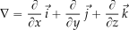
Recall that the vector gradient operator is defined as
(55) 
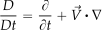
Hence, the substantial derivative operator can be written as
(56) 
The substantial derivative can be applied to any flow field variable, scalar, or vector. For example, if is the component of the velocity field  then
then  can be written as
(57) 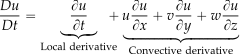
The term  is called the local derivative, which can be interpreted physically as the time rate of change of a given quantity at a fixed point. The term
  is called the convective derivative, which can be interpreted as the time rate of change from the movement of the given quantity from one point to another where its properties are spatially different. It will be apparent that terms like
  have units of time
 .
.
Notice that for a vector then  is
is
(58) 
which, in terms of the scalar components, is
(59) ![\begin{equation*} \frac{D\vec{V}}{Dt} = \begin{cases} \dfrac{D u}{Dt} = \dfrac{\partial u}{\partial t} + u\dfrac{\partial u}{\partial x} + v\dfrac{\partial u}{\partial y} + w\dfrac{\partial u}{\partial z} \\[16pt] \dfrac{D v}{Dt} = \dfrac{\partial v}{\partial t} + u\dfrac{\partial v}{\partial x} + v\dfrac{\partial v}{\partial y} + w\dfrac{\partial v}{\partial z} \\[16pt] \dfrac{D w}{Dt} = \dfrac{\partial w}{\partial t} + u\dfrac{\partial w}{\partial x} + v\dfrac{\partial w}{\partial y} + w\dfrac{\partial w}{\partial z} \end{cases} \end{equation*}](https://eaglepubs.erau.edu/app/uploads/quicklatex/quicklatex.com-a30297bc39aedcc4c55a2936d43f9938_l3.svg "Rendered by QuickLaTeX.com")
Check Your Understanding #13 – Calculating a substantial derivative
A fluid flows through a pipe, and the temperature distribution is given by  =
=  . What is the change in temperature at the point where the fluid velocity is
  ?
?
Show solution/hide solution.
The temporal change and the convective terms involving the gradients and velocity components must be obtained to calculate the substantial temperature derivative at that point. The substantial derivative is
![\[ \frac{D T}{Dt} = \frac{\partial T }{\partial t} + u \frac{\partial T }{\partial x} + v \frac{\partial T}{\partial y} + w\frac{\partial T}{\partial z} \]](https://eaglepubs.erau.edu/app/uploads/quicklatex/quicklatex.com-421c5fc8db661bf79ca96df37b07edc7_l3.svg "Rendered by QuickLaTeX.com")
The contributing terms are
(60) 
Therefore,
![\[ \frac{D T}{Dt} = 3 + 10 (2) + 5 (3) - 2 (-1) = 40~\mbox{units of temperature per unit time} \]](https://eaglepubs.erau.edu/app/uploads/quicklatex/quicklatex.com-ba39bac1edbade26ddc010e6ef0fdd23_l3.svg "Rendered by QuickLaTeX.com")
So, the substantial temperature derivative at the point in this example is 40.
Notice that the substantial derivative incorporates both the local temporal change in temperature and the convective transport from fluid motion. In this case, the local temporal change in temperature alone contributes a rate of 3 units per unit of time. The remaining terms, which involve convective transport and consider temperature gradients and fluid velocity, contribute to a total rate of 37 units per unit of time.
Ordinary Differential Equations (ODEs)
An ordinary differential equation (ODE) is an equation that involves the derivatives of a function with respect to a variable. A common engineering problem is solving an ordinary differential equation (ODE), i.e., determining the function (or functions) that will satisfy a given differential equation or a set of such equations. For example, given the ODE
(61) 
then what will be the function  ?
?
The antiderivative of  is
is  , so
, so
(62) 
where is some unknown constant. Therefore, solving an ODE is more complicated than just anti-differentiation because the value of the constant must also be determined. To this end, additional information, such as an initial or boundary condition, is required. Commonly, the value of will be known at some specific value of , e.g.,  . In this case, it will be apparent that
(63) 
for all values of t.
Check Your Understanding #14 – Solving ODEs
- Use the method of separation of variables to solve
![\[ \frac{dx}{dt} = 5x - 3 \]](https://eaglepubs.erau.edu/app/uploads/quicklatex/quicklatex.com-a0e923a4e6b80229d4251a4c9d76cc84_l3.svg "Rendered by QuickLaTeX.com")
Determine the function
. Take the particular case  to evaluate the integration constant.
 - Solve the first-order linear ordinary differential equation
![\[ \frac{dy}{dt} + 3y = 6e^{-2t} \]](https://eaglepubs.erau.edu/app/uploads/quicklatex/quicklatex.com-dc6b94b982db81c644615cae4fe7b59c_l3.svg "Rendered by QuickLaTeX.com")
subject to the initial condition
 .
. - Find the general solution of the second-order constant-coefficient ODE
![\[ \frac{d^{2}z}{dt^{2}} + 4z = 0 \]](https://eaglepubs.erau.edu/app/uploads/quicklatex/quicklatex.com-52155e110bd5b050024a835dd0e30833_l3.svg "Rendered by QuickLaTeX.com")
Show solutions / hide solutions.
-
- Separate the variables to get
![\[ \frac{dx}{5x-3} = dt \]](https://eaglepubs.erau.edu/app/uploads/quicklatex/quicklatex.com-e66be86234c9c84ba59a18aa4efe0ac6_l3.svg "Rendered by QuickLaTeX.com")
Integrating gives
![\[ \frac{1}{5}\ln|5x-3| = t + c \]](https://eaglepubs.erau.edu/app/uploads/quicklatex/quicklatex.com-755aeb70167d063bb035cdd2070fc46c_l3.svg "Rendered by QuickLaTeX.com")
so that
![\[ 5x - 3 = K e^{5t}, \quad K = e^{5x} \]](https://eaglepubs.erau.edu/app/uploads/quicklatex/quicklatex.com-9073e7375be4b6bf861c5c36b960043b_l3.svg "Rendered by QuickLaTeX.com")
Hence,
![\[ x(t) = \frac{3 + K e^{5t}}{5} \]](https://eaglepubs.erau.edu/app/uploads/quicklatex/quicklatex.com-10c2c866f4dc322d0e77e6a6ee00cc59_l3.svg "Rendered by QuickLaTeX.com")
Use the result that
 to find
  , i.e.,
  , i.e.,
  . Therefore
![\[ x(t) = \frac{3}{5} + \frac{2}{5}\,e^{5(t-2)} \]](https://eaglepubs.erau.edu/app/uploads/quicklatex/quicklatex.com-3a2a8306587a14199d21378b1cdacaaf_l3.svg "Rendered by QuickLaTeX.com")
- The integrating factor is
![\[ \mu(t) = e^{\int 3\,dt} = e^{3t} \]](https://eaglepubs.erau.edu/app/uploads/quicklatex/quicklatex.com-d175dc9d19abba0f4168e749e8ee7505_l3.svg "Rendered by QuickLaTeX.com")
Multiply through the equation to obtain
![\[ e^{3t} \frac{dy}{dt} + 3e^{3t} y = 6e^{(3-2)t} \]](https://eaglepubs.erau.edu/app/uploads/quicklatex/quicklatex.com-b81099752f38899263b1f81a24a406be_l3.svg "Rendered by QuickLaTeX.com")
so that
![\[ \frac{d}{dt} \bigl(e^{3t}y\bigr) = 6e^{t} \]](https://eaglepubs.erau.edu/app/uploads/quicklatex/quicklatex.com-57525de4e11e0dc50c23c7e29597619b_l3.svg "Rendered by QuickLaTeX.com")
Integrating gives
![\[ e^{3t}y = 6e^{t} + c \]](https://eaglepubs.erau.edu/app/uploads/quicklatex/quicklatex.com-574afcefc3ee7cfec2c82343658964dc_l3.svg "Rendered by QuickLaTeX.com")
so that
![\[ y(t) = 6e^{-2t} + c e^{-3t} \]](https://eaglepubs.erau.edu/app/uploads/quicklatex/quicklatex.com-324897dfc687fac5f8a3eeeb11b16d52_l3.svg "Rendered by QuickLaTeX.com")
Apply
 to get
  , i.e.,
  . Therefore,
![\[ y(t) = 6e^{-2t} - 5e^{-3t} \]](https://eaglepubs.erau.edu/app/uploads/quicklatex/quicklatex.com-5a951bf3829a31282418b7f734d445e8_l3.svg "Rendered by QuickLaTeX.com")
- The characteristic equation is
![\[ r^{2} + 4 = 0 \]](https://eaglepubs.erau.edu/app/uploads/quicklatex/quicklatex.com-4dd69b3b9d2bdcc3c960a85d1c060a2a_l3.svg "Rendered by QuickLaTeX.com")
so that
 . Therefore, the general solution is
![\[ z(t) = A \cos(2t) + B \sin(2t) \]](https://eaglepubs.erau.edu/app/uploads/quicklatex/quicklatex.com-7aa0e099e0e998d257d9ac8f8d6db36e_l3.svg "Rendered by QuickLaTeX.com")
where
and are arbitrary constants.
- Separate the variables to get
Partial Differential Equations (PDEs)
Partial differential equations (PDEs) involve equations with multiple independent variables and their corresponding partial derivatives. They model various engineering phenomena, including heat conduction, fluid dynamics, structural dynamics, elasticity, aeroelasticity, and acoustics.
PDEs can be classified into several types based on their order and linearity. The highest order of the partial derivatives involved determines the order of a PDE. For example, a second-order PDE involves second-order partial derivatives. Linearity refers to whether the equation is linear or nonlinear in terms of the unknown function and its derivatives.
Examples of PDEs include:
![\[ \frac{\partial u}{\partial t} = \alpha \left( \frac{ \partial^2 u}{ \partial x^2} + \frac{\partial^2 u}{\partial y^2} + \frac{ \partial^2 u }{ \partial z^2} \right) \]](https://eaglepubs.erau.edu/app/uploads/quicklatex/quicklatex.com-16c8ce9d4538a4fadd8e3ad80fafd779_l3.svg "Rendered by QuickLaTeX.com")
This equation is second-order, linear in , and parabolic. Its single time derivative balances a spatial Laplacian, so disturbances diffuse with finite speed without oscillations.
![\[ \frac{ \partial^2 u }{ \partial t^2} = a^2 \left (\frac{ \partial^2 u}{ \partial x^2} + \frac{ \partial^2 u} {\partial y^2} + \frac{ \partial^2 u }{\partial z^2} \right) \]](https://eaglepubs.erau.edu/app/uploads/quicklatex/quicklatex.com-f442a00ddb4089e57a8d50684dd3fa84_l3.svg "Rendered by QuickLaTeX.com")
This equation is second-order, linear, and hyperbolic. The second time derivative pairs with a spatial Laplacian, giving rise to propagating waves that carry information at the finite speed .
The Navier-Stokes Equations (incompressible, convective form)
![\[ \frac{ \partial \vec{V} }{\partial t} + (\vec{V} \bigcdot \nabla) \vec{V} = -\frac{1}{\varrho} \nabla p + \nu \nabla^2 \,\vec{V} \]](https://eaglepubs.erau.edu/app/uploads/quicklatex/quicklatex.com-4038b25e13c438eda577ead100a7bb9a_l3.svg "Rendered by QuickLaTeX.com")
It is second-order and nonlinear because of the convective term  . With viscosity present (
 ), the equation has a parabolic diffusion part, while the incompressibility constraint
  introduces an additional elliptic equation. The system is therefore a coupled, nonlinear, mixed parabolic-elliptic set of PDEs.
Needless to say, solving PDEs can be challenging, and different techniques are employed depending on the type of equation and its properties. For example, in incompressible flow theory, PDEs are used to determine velocity potentials and stream functions. Analytical methods involve finding exact solutions using techniques such as the separation of variables, a Fourier series, or Laplace transforms.
In general, exact, or analytical, solutions are feasible when the PDE is linear and the geometry or boundary data are simple. Typical techniques include separation of variables, Fourier series expansions, and Laplace transforms. When nonlinear terms or complex boundaries prevent closed-form solutions, numerical approximations based on finite-difference, finite-element, or finite-volume discretisations are employed. However, analytical solutions are not always possible, especially for nonlinear PDEs or complex boundary conditions. To this end, numerical methods are often used to approximate solutions for PDEs. These methods involve discretizing the domain and approximating the derivatives using finite difference, finite element, or finite volume techniques.
Examples for Potential Flows
For incompressible, irrotational flow the velocity potential and the stream function  both satisfy Laplace’s equation, i.e.,
(64) 
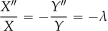
Assume  . Substituting into the Laplace equation gives
(65) 
leading to
(66) 
For example, in a domain with side lengths  and
and  , the separation constants are
(67) 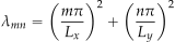
and the eigenfunctions are
(68) 
Boundary data are expanded in this sine basis, and the potential function is recovered as a double Fourier series.
As another example, consider the unsteady potential form of the potential equation, i.e.,
(69) 
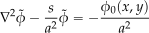
Taking the Laplace transform in , gives
(70) 
Using  , the PDE becomes the inhomogeneous Helmholtz equation
(71) 
Solve this elliptic problem (for example, by separation of variables) to obtain  . Finally, invert the transform using the Bromwich integral, i.e.,
(72) 
which yields the physical solution  that satisfies both the initial condition and any prescribed spatial boundary conditions.
Numerical Discretisation
When analytical techniques fail, discretisation is applied. On a uniform Cartesian grid, the two-dimensional Laplacian is approximated by the five-point stencil
(73) 
This second-order scheme produces a linear system of equations, i.e.,
(74) 
which can be solved efficiently with Gauss-Seidel, successive over-relaxation, or multigrid iteration.
Verification relies on grid-convergence studies and manufactured solutions, whereas validation compares results with experimental or benchmark data, such as potential flow over a cylinder or the lid-driven cavity. Combining analytical insight with robust numerical schemes lets engineers tackle the wide variety of incompressible-flow PDEs encountered in practice.
Check Your Understanding #15 – Partial differential equations
- In a specific incompressible potential flow, the velocity field
 in the
  -plane is given by
![\[ u = \frac{\partial \phi}{\partial x} = 2x, \qquad v = \frac{\partial \phi}{\partial y} = -2y \]](https://eaglepubs.erau.edu/app/uploads/quicklatex/quicklatex.com-cad8e50956496a3c62951961e09cc9b0_l3.svg "Rendered by QuickLaTeX.com")
Find the velocity potential
 .
. - Solve Laplace’s equation, i.e.,
![\[ \frac{\partial^{2}u}{\partial x^{2}} +\frac{\partial^{2}u}{\partial y^{2}} =0, \qquad 0 < x< L, 0<y<H \]](https://eaglepubs.erau.edu/app/uploads/quicklatex/quicklatex.com-4f0a0a08f8ad84872cce7991fbe7ff54_l3.svg "Rendered by QuickLaTeX.com")
subject to the boundary conditions
![\[ u(0,y) = 0, u(L,y) = 0, u(x,0) = 0, u(x,H) = f(x) \]](https://eaglepubs.erau.edu/app/uploads/quicklatex/quicklatex.com-5fd8b433de3883d2189ba49461ec7f8a_l3.svg "Rendered by QuickLaTeX.com")
Determine the harmonic function
 .
. - Solve the one-dimensional heat equation
![\[ u_t = \alpha^{2} u_{xx},\qquad 0 < x, \, t > 0 \]](https://eaglepubs.erau.edu/app/uploads/quicklatex/quicklatex.com-1a33a938fe8004313ee7773cbaac4788_l3.svg "Rendered by QuickLaTeX.com")
with the boundary conditions
 and initial condition
  . Find the temperature distribution
  .
.
Show solutions / hide solutions.
- Integrate the relation
 with respect to , giving
![\[ \phi = x^{2} + f_1(y) \]](https://eaglepubs.erau.edu/app/uploads/quicklatex/quicklatex.com-45c2d9346785a1ca8b7a8ba9034daec7_l3.svg "Rendered by QuickLaTeX.com")
Differentiating this result with respect to
and equating to the given velocity component  gives
gives  . Hence
  , and so
![\[ \phi(x,y) = x^{2} - y^{2} + c \]](https://eaglepubs.erau.edu/app/uploads/quicklatex/quicklatex.com-fe4739d1c160ca70fc128c236803964f_l3.svg "Rendered by QuickLaTeX.com")
- Assume a separable form
 . Separation of variables yields
![\[ \dfrac{X''}{X} = -\dfrac{Y''}{Y} = -\lambda \]](https://eaglepubs.erau.edu/app/uploads/quicklatex/quicklatex.com-0f00835002925a85f0256682f52a7faf_l3.svg "Rendered by QuickLaTeX.com")
Enforcing
 gives the eigen-pairs
![\[ \lambda_n = \left(\frac{n\pi}{L}\right)^2, \qquad X_n(x) = \sin \left(\frac{n\pi x}{L}\right) \]](https://eaglepubs.erau.edu/app/uploads/quicklatex/quicklatex.com-b83090d4bda6ad9dcc92e73944268d0b_l3.svg "Rendered by QuickLaTeX.com")
The corresponding
 solutions are
  . Express the top-wall data
  as a sine series, i.e.,
![\[ f(x) = \sum_{n=1}^{\infty} B_n \sin \left(\frac{n\pi x}{L}\right) \qquad B_n = \frac{2}{L}\int_{0}^{L} f(\xi)\sin \left(\frac{n\pi \xi}{L}\right)\,d\xi \]](https://eaglepubs.erau.edu/app/uploads/quicklatex/quicklatex.com-af40f580a8790cb81d977b080582ec24_l3.svg "Rendered by QuickLaTeX.com")
Therefore, the harmonic solution is
![\[ u(x,y) = \sum_{n=1}^{\infty} B_n \frac{\sinh \bigl(n\pi y/L\bigr)} {\sinh \bigl(n\pi H/L\bigr)} \sin \left(\frac{n\pi x}{L}\right) \]](https://eaglepubs.erau.edu/app/uploads/quicklatex/quicklatex.com-e4278379f85d46dd7caf986cfc6c9082_l3.svg "Rendered by QuickLaTeX.com")
- Let
 . After separation, then
![\[ \dfrac{T'}{\alpha^{2}T} = \dfrac{X''}{X} = -\lambda\]](https://eaglepubs.erau.edu/app/uploads/quicklatex/quicklatex.com-df004ca9aef4cc6ce026910b22032334_l3.svg "Rendered by QuickLaTeX.com")
The boundary conditions
give![\[ \lambda_n = \left(\frac{n\pi}{L}\right)^2,\qquad X_n(x) = \sin \left(\frac{n\pi x}{L}\right) \]](https://eaglepubs.erau.edu/app/uploads/quicklatex/quicklatex.com-ef7c664c7ad2bca3ba4373ec3e71e2d1_l3.svg "Rendered by QuickLaTeX.com")
The temporal factors satisfy
 , giving
![\[ T_n(t) = \exp \Bigl( -\alpha^{2}(n\pi/L)^{2}\,t \Bigr) \]](https://eaglepubs.erau.edu/app/uploads/quicklatex/quicklatex.com-7d1c2b71d17da8ca4d406f4a339c07ef_l3.svg "Rendered by QuickLaTeX.com")
Expand the initial profile
 as
as![\[ g(x) = \sum_{n=1}^{\infty} A_n \sin \left(\frac{n\pi x}{L}\right), \qquad A_n = \frac{2}{L}\int_{0}^{L} g(\xi)\sin \left(\frac{n\pi \xi}{L}\right)\,d\xi \]](https://eaglepubs.erau.edu/app/uploads/quicklatex/quicklatex.com-b25d5f0a314602f2d49c455e5e91c90e_l3.svg "Rendered by QuickLaTeX.com")
Therefore, the temperature distribution can be expressed by
![\[ u(x,t) = \sum_{n=1}^{\infty} A_n e^{-\alpha^{2}(n\pi/L)^{2}t} \sin \left(\frac{n\pi x}{L}\right) \]](https://eaglepubs.erau.edu/app/uploads/quicklatex/quicklatex.com-4be189d1bbfb7edd5402110bb73849ff_l3.svg "Rendered by QuickLaTeX.com")
Other Coordinate Systems
In engineering, several coordinate systems are used to describe and analyze spatial relationships and physical phenomena. Cartesian coordinates, using orthogonal axes , , and , are natural coordinates and are fundamental for geometric modeling and structural analysis in three-dimensional space. Polar coordinates, defined by radial distance  and azimuthal angle , are valid for applications involving radial symmetry. Cylindrical coordinates expand upon polar coordinates with an added vertical dimension , making them ideal for radial problems with cylindrical and axial symmetry. Spherical coordinates arise in some contexts, incorporating radial distance , polar angle , and azimuthal angle . Lastly, curvilinear coordinates, which encompass systems such as elliptic and parabolic coordinates, also find applications in engineering.
Polar Coordinates
Polar coordinates often arise in engineering problem-solving. A polar coordinate system is a two-dimensional coordinate system in which each point in a plane is defined by its distance from a reference point and the angle it forms with a reference direction. This axis system is advantageous for problems involving radial symmetry, such as fluid dynamics and structural analysis.
In the polar system, the radial coordinate, , is the distance from the origin at point O to another point, P. The corresponding angular coordinate, , is shown in the figure below; is measured counterclockwise from the positive -axis to the line connecting the origin to the point.
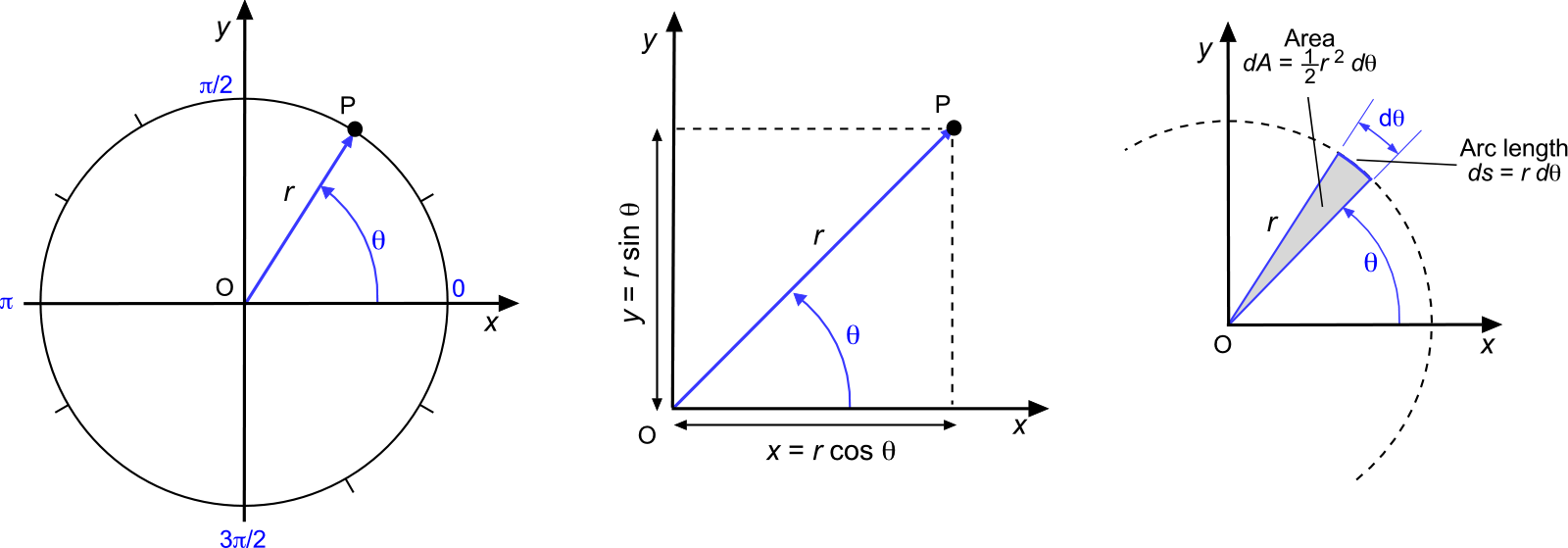
Polar coordinates are easily converted into Cartesian coordinates by using the transformation
(75) 
and from Cartesian coordinates to polar coordinates using
(76) 
Notice that the differential elements in polar coordinates are  for the arc length and
  for the area element, both of which frequently occur in engineering problem-solving.
The principal value of the inverse tangent function typically returns an angle in the range  to
to  (or -90° to 90°). The tangent function is periodic, and the inverse function needs a unique range for every output value. The inverse tangent function alone does not account for the correct quadrant of the angle because
  is positive for both the first and third quadrants and negative for both the second and fourth quadrants. To handle this, the atan2 function is used, which is a function available on all scientific calculators, i.e.,
(77) 
This function returns the angle in the correct quadrant by considering the signs of both and . It returns the angle and its correct sign in the range  to
to  (or -180° to 180°).
In polar coordinates, the commonly used vector operators are the gradient of a scalar field, i.e.,
(78) 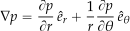
where is a scalar field, and  and
and  are the unit vectors in the and directions, respectively. The divergence of a vector is
(79) 
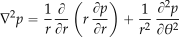
Finally, the Laplacian operator is
(80) 
Cylindrical & Spherical Coordinates
Cylindrical coordinates are an axisymmetric extension of polar coordinates. They are helpful for modeling problems involving cylindrical objects, such as pipes, shafts, and columns. In cylindrical coordinates  , each component has a specific role in defining the position of a point in three-dimensional space, as shown in the figure below. Spherical coordinates
  are the position of a point in space using three values: radial distance, polar angle, and azimuthal angle.
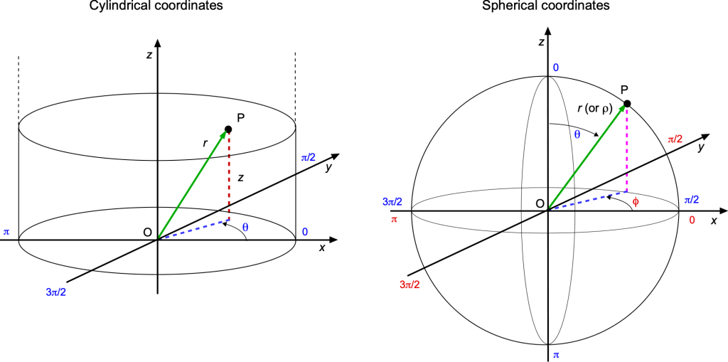
The radial coordinate represents the radial distance from the origin to the point projected onto the  plane. It is similar to the in polar coordinates but extends vertically into three dimensions. The azimuthal angle, , is the counterclockwise angle from the positive -axis to the point projection onto the -plane. The vertical coordinate denotes the vertical height above (or below) the plane.
Converting from Cartesian to cylindrical coordinates is done by using the transformation
(81) 
and from cylindrical to Cartesian coordinates by using
(82) 
In spherical coordinates, the radial distance is often denoted by  and in some contexts, mainly because of symbol conflicts with fluid parameters. The polar angle, , is the angle between the positive -axis and the line from the origin to the point. The azimuthal angle, , is the angle between the positive -axis and the projection onto the -plane.
Converting from Cartesian to spherical coordinates is performed using
(83) 
and spherical to Cartesian coordinates using
(84) 
Transformations
In mathematics, transformations are operations that map a set of points or coordinates defining a body or some equation(s) to another set of points or equations, altering the position, size, shape, or orientation of the initial values. Transformation operations are fundamental to a wide range of engineering applications.
Translation
One type of transformation is a translation, as shown in the figure below for two-dimensional space, which shifts every point of a body defined in space by the same distance in a given direction. For example, translating a point  by 3 units to the right and 4 units up, the new coordinates P’ will be
(85) 
Translation moves bodies or coordinates without altering their orientation or size.
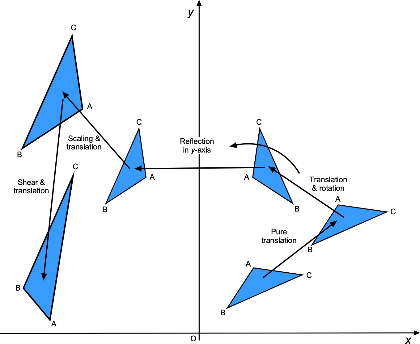
Rotation
Rotation turns a set of points defining a body about a fixed point through a specified angle. For instance, by rotating P 90 counterclockwise (e.g., about the origin), the new coordinates P’ are
(86) 
Rotation is a transformation used in solving many types of engineering problems.
Reflection
Reflection flips the set of points defining the shape of a body, thereby producing its mirror image. For example, reflecting P over the -axis, the new coordinates P’ are
(87) 
This type of transformation is fundamental in understanding and solving problems that use planar symmetry.
Scaling
Scaling, or dilation, enlarges or reduces a body by a scale factor relative to a fixed point. If point P is scaled by a factor of 2 with respect to the origin, the new coordinates P’ are
(88) 
Scaling is essential in similarity transformations, which occur frequently in engineering.
Shear
Shear distorts the body’s shape by sliding one part of it parallel to a fixed line. For example, in a shear transformation where the -coordinates are unchanged but the -coordinates are shifted by twice the -coordinate value, the new coordinates P’ are
(89) 
Shear transformations occur in engineering problems involving stress and deformation.
Affine Transformations
Affine transformations include translation, rotation, scaling, shear, preserving points, straight lines, and planes. An affine transformation is any transformation that preserves collinearity (i.e., all points lying on a line initially still lie on a line after transformation) and ratios of distances (e.g., the midpoint of a line segment remains the midpoint after transformation). Projective transformations extend affine transformations and include perspective projections. An affine transformation can be represented as
(90) 
where is a matrix representing the linear part of the transformation,  is a vector representing the translation, and
  is the input vector.
Transformation in the Lifting Line Theory
The lifting line theory is an aerodynamic method used to analyze finite wings. The lifting line theory uses the transformation to relate the spanwise position along the wing to the angle . The spanwise position along the wing is transformed into an angular coordinate using
![\[ y = -\frac{b}{2} \, \cos \theta = -s \, \cos \theta \]](https://eaglepubs.erau.edu/app/uploads/quicklatex/quicklatex.com-9b9017a55fb4bf466d6abbdbfaca5462_l3.svg "Rendered by QuickLaTeX.com")
where is the wing span is the semi-span, is the spanwise coordinate, ranging from  to
to  or
or  to , is the angle in the transformed angular coordinate ranging from
  to . This transformation maps the spanwise coordinate to the angular coordinate, making it easier to apply Fourier series solution techniques.
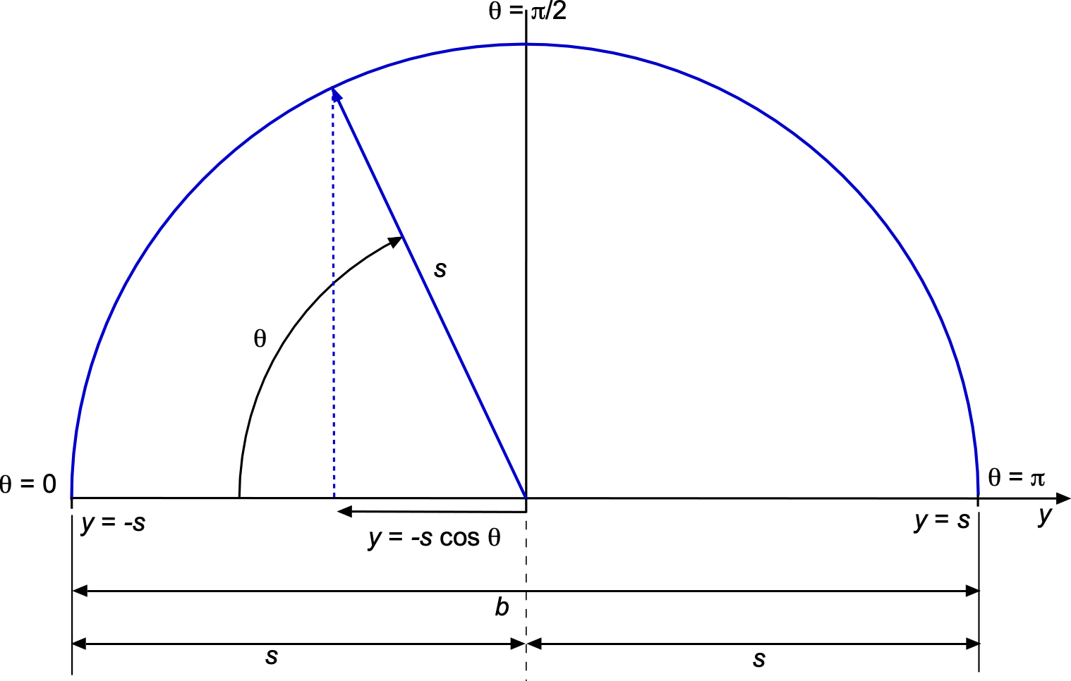
Nonlinear Transformations
Nonlinear transformations can take various forms. Examples include polynomial transformations such as
(91) 
There are also exponential transformations, such as
(92) 
as well as logarithmic transformations, i.e.,
(93) 
Complex Numbers
A complex number  combines a “real” part and an “imaginary” part . Engineering work can leverage complex number theory to simplify the mathematics. The use of complex numbers appears throughout core engineering classes because they package the dimensions of magnitude and direction into a single quantity, collapsing differential-equation bookkeeping, all of which reduces to ordinary algebra or trigonometry once the rules such as
  are kept in mind.
The addition and subtraction of complex numbers combine the like parts, i.e.,
(94) 
The multiplication of complex numbers follows the distributive law of algebra. Collecting real and imaginary terms gives
(95) 
Complex numbers are often expressed in their polar (exponential) form, i.e.,
(96) 
where the modulus  sets the length of the vector and the exponential factor
  rotates the vector through an angle . If
(97) 
then their product becomes
(98) 
Therefore, their magnitudes multiply and their arguments add.
Division is equally simple in polar form, but in Cartesian form it is usually performed by multiplying the numerator and denominator by the complex conjugate, i.e.,  , so that
(99) 
where the modulus is
(100) 
The argument (phase) is defined by
(101) 
so can be reconstructed from its modulus and argument as
(102) 
which is the famous Euler’s identity, condensing the cosine and sine components into a single exponential function.
Powers and roots of complex numbers follow directly. In polar form, then
(103) 
so raising a complex number to the  th power multiplies its modulus by itself times and adds its argument times. Correspondingly, the th roots are
(104) 
thereby revealing the equally spaced root pattern commonly encountered in solving differential equations and various engineering problems.
Aerospace engineers often first see the use of complex number theory in the study of dynamics and control, as well as two-dimensional potential flows. In advanced classes, they turn up in descriptions of unsteady aerodynamics and aeroelasticity. Mastering the use of complex numbers is largely a matter of recognising when to switch between Cartesian and polar forms. For example, lumped spring-mass-damper system obeys the canonical form  . Assuming a complex displacement
  converts the differential equation into the algebraic relation
 ![\hat{x} = F_0/[k - m\omega^{2} + i \, c\omega]](https://eaglepubs.erau.edu/app/uploads/quicklatex/quicklatex.com-1b4d55806faeab5233e72050d6f3efa2_l3.svg "Rendered by QuickLaTeX.com") . The complex denominator reveals resonance when its magnitude is smallest, and its phase tells how far the mass lags the forcing. In aerodynamics, complex potentials
. The complex denominator reveals resonance when its magnitude is smallest, and its phase tells how far the mass lags the forcing. In aerodynamics, complex potentials  can help solve two-dimensional, incompressible, irrotational flows because both the velocity potential and the stream function satisfy Laplace’s equation, i.e.,
  and
and  .
.
Matrices and Systems of Linear Equations
A matrix is a rectangular array of numbers organized into rows and columns. It is denoted as having dimensions  , where = the number of rows and = the number of columns. Matrices are widely used to represent and solve systems of equations, perform transformations, and model phenomena in various engineering applications.
Types of Matrices
A square matrix has the same number of rows and columns ( ), e.g.,
(105) ![\begin{equation*} \begin{bmatrix} 1 & 2 & 3 \\[6pt] 4 & 5 & 6 \\[6pt] 7 & 8 & 9 \end{bmatrix} \end{equation*}](https://eaglepubs.erau.edu/app/uploads/quicklatex/quicklatex.com-584bc3d56cceb064a4f85caa0db08a43_l3.svg "Rendered by QuickLaTeX.com")
The identity matrix ( ) is a square matrix with 1s on the diagonal and 0s elsewhere. Multiplying any matrix by results in (
 ), i.e.,
(106) ![\begin{equation*} A \, I = \begin{bmatrix} 1 & 2 & 3 \\[6pt] 4 & 5 & 6 \\[6pt] 7 & 8 & 9 \end{bmatrix} \, \begin{bmatrix} 1 & 0 & 0 \\[6pt] 0 & 1 & 0 \\[6pt] 0 & 0 & 1 \end{bmatrix} = \begin{bmatrix} 1 & 2 & 3 \\[6pt] 4 & 5 & 6 \\[6pt] 7 & 8 & 9 \end{bmatrix} \end{equation*}](https://eaglepubs.erau.edu/app/uploads/quicklatex/quicklatex.com-53b512a5a75e7e0f401d2794f051c29b_l3.svg "Rendered by QuickLaTeX.com")
A zero matrix has all elements equal to 0, i.e.,
(107) ![\begin{equation*} \begin{bmatrix} 0 & 0 & 0\\[6pt] 0 & 0 & 0\\[6pt] 0 & 0 & 0 \end{bmatrix} \end{equation*}](https://eaglepubs.erau.edu/app/uploads/quicklatex/quicklatex.com-c4f29e5341c054f9f0e3ee6609a0a89f_l3.svg "Rendered by QuickLaTeX.com")
A diagonal matrix has non-zero elements only on the diagonal, e.g.,
(108) ![\begin{equation*} \begin{bmatrix} 5 & 0 & 0\\[6pt] 0 & 7 & 0\\[6pt] 0 & 0 & 9 \end{bmatrix} \end{equation*}](https://eaglepubs.erau.edu/app/uploads/quicklatex/quicklatex.com-44e5af321db14aabca5b9ee4cd62f78a_l3.svg "Rendered by QuickLaTeX.com")
A symmetric matrix is a square matrix that is equal to its transpose, i.e.,  . This means that the element in the
  -th row and
  -th column (
 ) is equal to the element in the -th row and -th column (
 ) for all
  . For example, a symmetric matrix is
(109) ![\begin{equation*} A = \begin{bmatrix} 1 & 2 & 3 \\[6pt] 2 & 5 & 6 \\[6pt] 3 & 6 & 9 \end{bmatrix} \end{equation*}](https://eaglepubs.erau.edu/app/uploads/quicklatex/quicklatex.com-7f8d7f7db9cd22363a278e09718c2c0d_l3.svg "Rendered by QuickLaTeX.com")
To verify that is symmetric, its transpose  is obtained by flipping the matrix over its diagonal, i.e.,
(110) ![\begin{equation*} A^T = \begin{bmatrix} 1 & 2 & 3 \\[6pt] 2 & 5 & 6 \\[6pt] 3 & 6 & 9 \end{bmatrix} \end{equation*}](https://eaglepubs.erau.edu/app/uploads/quicklatex/quicklatex.com-fa6c010db8e20c638c2ab8cba7632333_l3.svg "Rendered by QuickLaTeX.com")
Because , this matrix is symmetric.
Matrix Operations
Addition and subtraction are performed element-wise, and matrices must have the same dimensions, e.g.,
(111) ![\begin{equation*} A = \begin{bmatrix} 1 & 2 \\[6pt] 3 & 4 \end{bmatrix} \quad \text{and} \quad B = \begin{bmatrix} 5 & 6 \\[6pt] 7 & 8 \end{bmatrix} \end{equation*}](https://eaglepubs.erau.edu/app/uploads/quicklatex/quicklatex.com-05e78fe4e7aa8c150a2696167bc5229c_l3.svg "Rendered by QuickLaTeX.com")
then
(112) ![\begin{equation*} A + B = \begin{bmatrix} 6 & 8 \\[6pt] 10 & 12 \end{bmatrix} \end{equation*}](https://eaglepubs.erau.edu/app/uploads/quicklatex/quicklatex.com-8e1964c2ac19e5d94859baa035a9b9c9_l3.svg "Rendered by QuickLaTeX.com")
Matrix multiplication is defined when the number of columns in the first matrix equals the number of rows in the second, i.e.,
(113) 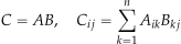
For example, consider
(114)
then
(115) ![\begin{equation*} A \, B = \begin{bmatrix} 19 & 22 \\[6pt] 43 & 50 \end{bmatrix} \end{equation*}](https://eaglepubs.erau.edu/app/uploads/quicklatex/quicklatex.com-e107d07b97c284cd246c47ee1ca4d3c5_l3.svg "Rendered by QuickLaTeX.com")
The transpose of a matrix flips it over its diagonal, i.e.,
(116) ![\begin{equation*} A = \begin{bmatrix} 1 & 2 \\[6pt] 3 & 4 \end{bmatrix}, \quad A^T = \begin{bmatrix} 1 & 3 \\[6pt] 2 & 4 \end{bmatrix} \end{equation*}](https://eaglepubs.erau.edu/app/uploads/quicklatex/quicklatex.com-45c39b8d26c600165431d18554fbbb70_l3.svg "Rendered by QuickLaTeX.com")
A matrix is invertible if  . The inverse
  satisfies
(117) 
Systems of Linear Equations
A system of linear equations can be written in matrix form as
(118) 
where = coefficient matrix, = column vector of variables, and = column vector of constants. Solving systems of linear equations is a fundamental task in engineering. A system of linear equations can be represented in matrix form as  , where is the coefficient matrix, is the column vector of unknowns, and is the column vector of constants.
Depending on the properties of the coefficient matrix , such as its invertibility and rank, various methods can be applied to find solutions. These methods include row reduction (also known as Gaussian elimination), matrix inversion, LU decomposition, and Cramer’s Rule. Each technique offers specific advantages and is suited to different types of systems and computational requirements.
Row Reduction (Gaussian Elimination)
This method involves converting the coefficient matrix into row echelon form (or reduced row echelon form) using elementary row operations. The steps are:
- Swap rows to position a non-zero pivot element in the first row, first column.
- Normalize the pivot element to 1 by dividing the entire row by its value.
- Eliminate all elements below the pivot by subtracting suitable multiples of the pivot row from the rows beneath.
- Repeat the process for subsequent rows to create a triangular matrix in row echelon form.
- Solve for variables starting from the last row (back-substitution).
For example, to solve the system
(119) 
the augmented matrix is
(120) ![\begin{equation*} \begin{bmatrix} 2 & 1 & 5 \\[6pt] 4 & 3 & 6 \end{bmatrix} \end{equation*}](https://eaglepubs.erau.edu/app/uploads/quicklatex/quicklatex.com-45c535138b9009baec92b1a5ad5b9f2d_l3.svg "Rendered by QuickLaTeX.com")
Dividing the first row by 2 to make the pivot element in the first column equal to 1 gives
(121) ![\begin{equation*} \begin{bmatrix} 1 & 0.5 & 2.5 \\[6pt] 4 & 3 & 6 \end{bmatrix} \end{equation*}](https://eaglepubs.erau.edu/app/uploads/quicklatex/quicklatex.com-6f41e2755baab8d2fba3b02e9f2d23a8_l3.svg "Rendered by QuickLaTeX.com")
Subtracting 4 times the first row from the second row gives
(122) ![\begin{equation*} \begin{bmatrix} 1 & 0.5 & 2.5 \\[6pt] 0 & 1 & -4 \end{bmatrix} \end{equation*}](https://eaglepubs.erau.edu/app/uploads/quicklatex/quicklatex.com-ee9c5c3e84fd19301ddbfb0bffcf0da1_l3.svg "Rendered by QuickLaTeX.com")
From the second row, then  . Substituting this value into the first row yields
  .
.
Matrix Inversion
If the coefficient matrix is invertible (), the system can be solved using
(123) 
The steps are:
- Compute the determinant of . The system has no unique solution if
 .
. - Find the inverse using cofactor expansion or row reduction methods.
- Multiply by to find .
This method is computationally expensive, i.e., too many arithmetic operations, for large systems and is often avoided unless necessary.
LU Decomposition
This method decomposes into two triangular matrices, i.e.,
(124) 
where  is a lower triangular matrix and
  is an upper one. The solution process involves:
- Decompose into and .
- Solve
 for using forward substitution.
 - Solve
 for using back substitution.
Consider, for example, the system
(125) ![\begin{equation*} A = \begin{bmatrix} 2 & 3 \\[6pt] 4 & 7 \end{bmatrix} \quad \text{and} \quad b = \begin{bmatrix} 5 \\[6pt] 10 \end{bmatrix} \end{equation*}](https://eaglepubs.erau.edu/app/uploads/quicklatex/quicklatex.com-a8e7ee3d78567d344352aad25d4c5b2f_l3.svg "Rendered by QuickLaTeX.com")
Decomposing gives
(126) ![\begin{equation*} L = \begin{bmatrix} 1 & 0 \\[6pt] 2 & 1 \end{bmatrix} \quad \text{and} \quad U = \begin{bmatrix} 2 & 3 \\[6pt] 0 & 1 \end{bmatrix} \end{equation*}](https://eaglepubs.erau.edu/app/uploads/quicklatex/quicklatex.com-70b4165ddfdbacafa7e40a7025cffc54_l3.svg "Rendered by QuickLaTeX.com")
Solve and then  to find .
Cramer’s Rule
For a square matrix , Cramer’s Rule solves each variable  as
as
(127) 
where  is obtained by replacing the -th column of with .
The steps are:
- Compute
 . The system has no unique solution if .
 - Replace each column of with one at a time to form .
- Compute
 for each .
 - Solve for using the formula above.
For example, if
(128) ![\begin{equation*} A = \begin{bmatrix} 2 & 3 \\[4pt] 1 & 4 \end{bmatrix} \quad \text{and} \quad b = \begin{bmatrix} 5 \\[4pt] 6 \end{bmatrix} \end{equation*}](https://eaglepubs.erau.edu/app/uploads/quicklatex/quicklatex.com-22b12cea13ba8402d0f6128620fcb60a_l3.svg "Rendered by QuickLaTeX.com")
The solution for  is
is
(129) ![\begin{equation*} x_1 = \frac{\text{det} \begin{bmatrix} 5 & 3 \\[4pt] 6 & 4 \end{bmatrix}}{\text{det} \begin{bmatrix} 2 & 3 \\[4pt] 1 & 4 \end{bmatrix}} = \frac{2}{5} \end{equation*}](https://eaglepubs.erau.edu/app/uploads/quicklatex/quicklatex.com-f7d3f53e396b2f5619214515a2861463_l3.svg "Rendered by QuickLaTeX.com")
Worked Example #16 – Solving a set of linear simultaneous equations
 and
and  .
.Show solution/hide solution.
The system of equations is
![\[ 2x + 3y = 5 \quad \text{and} \quad 4x - y = 6 \]](https://eaglepubs.erau.edu/app/uploads/quicklatex/quicklatex.com-cc90e99c54d3e8852c5b8a75ceb80e2f_l3.svg "Rendered by QuickLaTeX.com")
In matrix form, these can be written as
![\[ \begin{bmatrix} 2 & 3 \\[4pt] 4 & -1 \end{bmatrix} \begin{bmatrix} x \\[4pt] y \end{bmatrix} = \begin{bmatrix} 5 \\[5pt] 6 \end{bmatrix} \]](https://eaglepubs.erau.edu/app/uploads/quicklatex/quicklatex.com-5dce4adc5cae6110ab111a6095989ba8_l3.svg "Rendered by QuickLaTeX.com")
The determinant of the coefficient matrix is
![\[ \text{det}(A) = \begin{vmatrix} 2 & 3 \\[4pt] 4 & -1 \end{vmatrix} = (2)(-1) - (4)(3) = -2 - 12 = -14 \]](https://eaglepubs.erau.edu/app/uploads/quicklatex/quicklatex.com-47a17ae869c9eb097418a5e8bf0538e6_l3.svg "Rendered by QuickLaTeX.com")
The inverse of a 2 x 2 matrix is
![\[ A^{-1} = \frac{1}{\text{det}(A)} \begin{bmatrix} d & -b \\[4pt] -c & a \end{bmatrix} \]](https://eaglepubs.erau.edu/app/uploads/quicklatex/quicklatex.com-7605e23519dde145a89596a608919936_l3.svg "Rendered by QuickLaTeX.com")
Substituting the values gives
![\[ A^{-1} = \frac{1}{-14} \begin{bmatrix} -1 & -3 \\[4pt] -4 & 2 \end{bmatrix} = \begin{bmatrix} \dfrac{1}{14} & \dfrac{3}{14} \\[10pt] \dfrac{4}{14} & -\dfrac{2}{14} \end{bmatrix} \]](https://eaglepubs.erau.edu/app/uploads/quicklatex/quicklatex.com-e74efea0599bafd23fb229448ba5d3e0_l3.svg "Rendered by QuickLaTeX.com")
To solve for , use
![\[ x = A^{-1}b \]](https://eaglepubs.erau.edu/app/uploads/quicklatex/quicklatex.com-c68590b50062b646f46edab75ce0fbb3_l3.svg "Rendered by QuickLaTeX.com")
Substituting gives
![\[ x = \begin{bmatrix} -\dfrac{1}{14} & -\dfrac{3}{14} \\[10pt] -\dfrac{4}{14} & \dfrac{2}{14} \end{bmatrix} \begin{bmatrix} 5 \\[12pt] 6 \end{bmatrix} \]](https://eaglepubs.erau.edu/app/uploads/quicklatex/quicklatex.com-68a0a6011958bbc511d9d9f9106bab0f_l3.svg "Rendered by QuickLaTeX.com")
Performing the matrix multiplication gives
![\[ x = \begin{bmatrix} -\dfrac{23}{14} \\[12pt] -\dfrac{4}{7} \end{bmatrix} \]](https://eaglepubs.erau.edu/app/uploads/quicklatex/quicklatex.com-b36c3c0a448d2cea7b23b00260ec4fb8_l3.svg "Rendered by QuickLaTeX.com")
Therefore, the solution to the system is
![\[ x = -\dfrac{23}{14} \quad \text{and} \quad y = -\dfrac{4}{7} \]](https://eaglepubs.erau.edu/app/uploads/quicklatex/quicklatex.com-ff0170c52dd1af353b11c7ba48338745_l3.svg "Rendered by QuickLaTeX.com")
Working with Numbers
In engineering problems, information is often presented as numbers that must be manipulated to find a final answer. Much engineering work is done with numbers, and it is frequently said that anything else can only be an opinion, i.e., the truth can only be expressed in numbers or data. In this process, questions may arise about whether it is necessary to round numbers to a specific number of decimal places and/or significant digits. Common sense generally prevails, but some guidelines should be followed.
Rounding Decimals
Sometimes, a number must be rounded to a certain number of decimal places or even to a whole number. To this end, some numbers must be removed from the decimals at the end of the number. The method is to look at the value of the following number after the one to stop at, then apply the rules for rounding:
- Round up if the first digit to be discarded exceeds, e.g., 3.14159 is 3.1416 to 4 decimal places.
- Round down if the first digit to be discarded is below 5. e.g., 3.141592 is 3.14159 to 5 decimal places.
- If the first discarded digit is 5, round up if a non-zero digit follows it, but round down if it is followed by a zero. For example, 3.14159 is 3.142 to 3 decimal places.
In multi-step calculations, rounding up or down of numbers is generally permitted only at the end of the calculation. The appropriate number of decimal places (or, otherwise, the accepted accuracy of the known quantities) must be carried forward and then finally rounded off, as needed. However, rounding off intermediate numbers may be avoided altogether in many cases. Instead, the known numbers with an acceptable level of accuracy to a certain number of decimal places are used. However, using numbers to 8 decimal places is usually unnecessary.
Remember that if rounding off numbers is needed, which is often the case, it is usually done only at the end of the calculation. To this end, common-sense rules for rounding numbers generally prevail. Rounding 9.81 to 9.8 may be acceptable (1 decimal place or two significant digits), but rounding to 10.0 is unacceptable. Rounding 0.002378 to 0.00238 may be fine, but rounding to 0.02 is generally intolerable. Rounding 3.14156 to 3.142 may be acceptable, but rounding to 3.0 is unacceptable.
Significant Digits
Significant digits are the total number used to express a measured or calculated quantity. Like decimal places, significant digits measure how “precise” a number is given. The value with the fewest significant digits sets the standard for the degree of precision.
Generally, the goal is to perform numerical calculations involving values that have (approximately) the same number of significant digits to obtain an answer with the required (or maximum possible) accuracy. There are also some simple rules for significant digits:
- All non-zero digits in a number are always considered significant.
- Any zeros appearing in a number between two non-zero digits are considered significant.
- A final zero or trailing zeros in the decimal portion are considered significant.
Check Your Understanding #17 – Significant digits
- How many significant digits are in 14.638?
- How many significant digits are in 0.002378?
- How many significant digits are in 273.70?
Show solution/hide solution.
- Answer = 5; 2. Answer = 4; 3. Answer = 5
Manipulating Numbers
There are a few basic rules that should be followed when manipulating numbers:
- Addition and subtraction. Generally, the answer should have the same number of decimal places as the term with the fewest decimal places, e.g., 4.123 + 2.56 = 6.68.
- Multiplication and division. Generally, the answer should have the same number of significant digits as the term with the fewest significant digits, e.g., 4.121 × 6.62 = 27.3.
- Integers are always treated as having an infinite number of significant digits; e.g., 5 is considered for operations as 5.000…
Check Your Understanding #18 – Accuracy
You are being asked to determine the disk area of a propeller used on a drone by using a ruler to measure its diameter and then using the formula for the area of a circle. The nominal diameter of the propeller is 250 mm. How should the area value be reported numerically in terms of accuracy? A ruler can be read to about 0.1 millimeters.
Show solution/hide solution.
A ruler can be read to approximately 0.1 millimeters, so if the disk’s diameter were reported as 250.1 mm (4 significant digits), that would be a suitable measurement. Therefore, the calculated area is  = 49,126.7 mm
 . However, if this area value is reported, it implies a higher precision than the original measurement of the diameter. Therefore, by rounding, the area must only be reported to 4 significant digits as 49,130 mm. If the diameter could be measured to 2 decimal places (e.g., 250.13 mm, which has 5 significant digits), the area could be reported as 49,127.0 mm.
Finally, common-sense rules should also be applied when working with numbers in engineering calculations. For example, it would be inappropriate to round up “g” (acceleration under gravity) from 9.81 m/s2 to 10.0 m/s2 when simultaneously using the value of to 4 decimal places in the same calculation. Sometimes, when doing homework, it is necessary to put down the calculator and pencil, apply common sense, and say: “Based on what I just did, does this numerical answer seem right?” Ultimately, obtaining the “right” numerical answers in problem-solving means understanding the basic concepts of significant digits and rounding, as well as learning how to identify likely numerical errors. Spotting errors requires experience, and experience is only gained through extensive practice.
Summary & Closure
The ability of engineers to apply the necessary mathematical concepts is an essential aspect of problem-solving. Geometry, algebra, trigonometry, calculus, and differential equations provide engineers with the crucial mathematical tools to solve complex problems, quantify processes, and make informed decisions. For example, many engineering problems involve vector quantities (e.g., forces, velocities, accelerations), which may require various vector operations, such as scalar and vector products, line and surface integrals, volume integrals, and gradients. Additionally, calculus introduces other mathematical tools that are often essential for engineering problem-solving. For example, besides pure mathematics, engineers nearly always require numerical results that must be evaluated accurately and consistently, with a consistent number of significant digits or decimal places based on the available data.
5-Question Self-Assessment Quickquiz
For Further Thought or Discussion
- Explain the fundamentals of a scalar quantity. Make a list of some familiar scalar quantities used in engineering.
- Explain the fundamentals of a vector quantity. Make a list of some examples of vector quantities used in engineering.
- Explain the physical meaning of the curl of a vector field. Is the curl of a uniform flow positive, negative, or zero?
- What happens when the simple rules of significant digits are not used in basic arithmetic calculations?
- What happens when numbers are prematurely rounded up or down, and there is still a need to carry forward the needed number of significant digits in complex arithmetic calculations?
- If the function
 where is a constant, then what is
  ? Your answer may depend on whether you are biased toward pure mathematics, physics, or engineering.
Other Useful Online Resources
There is more to explore with these mathematical concepts:
- This video offers a more in-depth examination of vector fields, divergence, and curl.
- If you want to learn more about the Laplace equation, this website provides a wealth of information on the topic, as well as other mathematical operations.
- All The Math You Need For Engineering: The Ultimate Guide (Step-by-Step).
- Maths Every Engineer Must Know To Be Successful & Why.
- You can’t suck at maths and be an engineer – an informative and motivational video.
- "It’s all about mathematics!" Whether it’s fluid dynamics, aerodynamics, or orbital mechanics, the foundation often comes down to understanding and using mathematical principles. ↵
- "Errors in engineering are often catastrophes." In engineering, even minor miscalculations can lead to severe consequences, which is why double-checking, simulations, and testing are vital to avoiding catastrophic outcomes. ↵
- "Practice makes perfect." Consistent practice is essential for mastery. Whether designing a flight control system or finding optimal airfoil shapes, practice refines understanding and long-term skills. ↵
- At face value, i.e., on-demand, as needed. ↵
- Work smart, not hard." Efficiency and cleverness are crucial in accomplishing tasks, rather than relying solely on sheer effort. ↵