38 Fundamentals of Propulsion Systems
Introduction
All flight vehicles require a propulsion system to sustain flight, the only exception being a glider or a sailplane. The term “propulsion” refers to the creation of a force that propels a system forward. For example, a propulsion system for an aircraft, known as an air-breathing propulsion system, consists of a mechanical power source (i.e., an engine of some kind) and a propulsor capable of doing work on the air to increase its momentum, thereby converting this engine power into a propulsive force. This can be done using a jet efflux, as shown in the figure below, or by a propeller’s action on the air. Increasing the time rate of change of momentum of the fluid as it goes through the propulsion system produces the thrust to propel the aircraft forward.
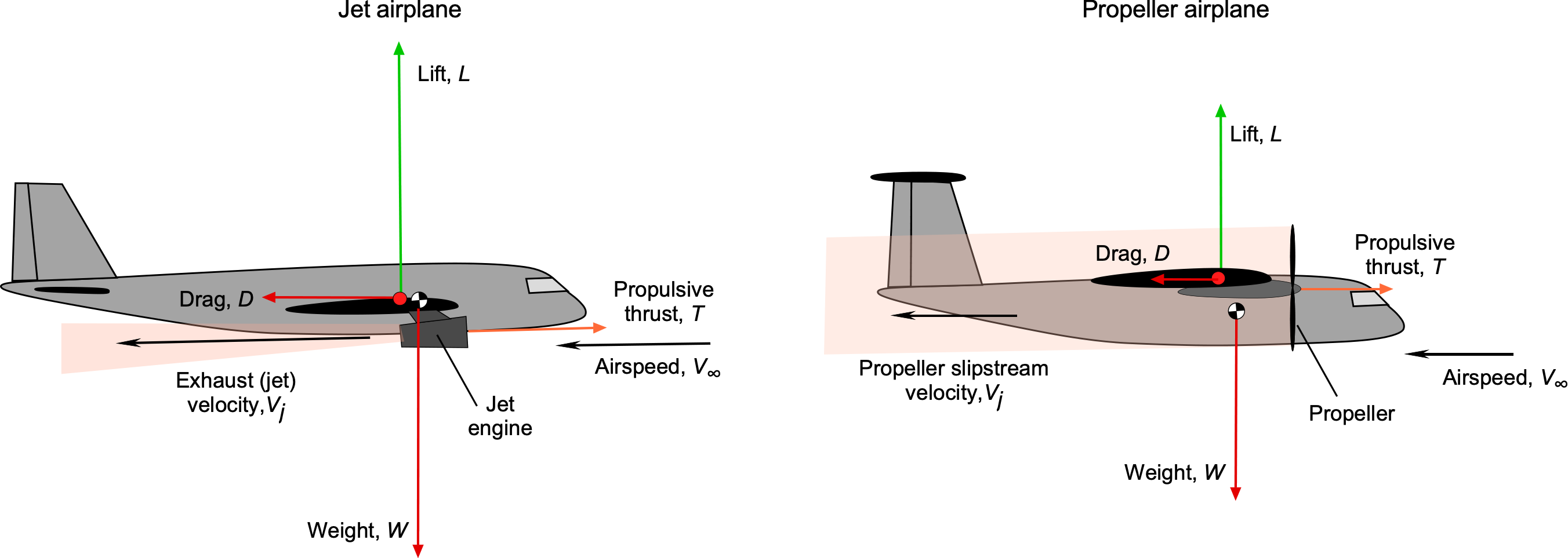
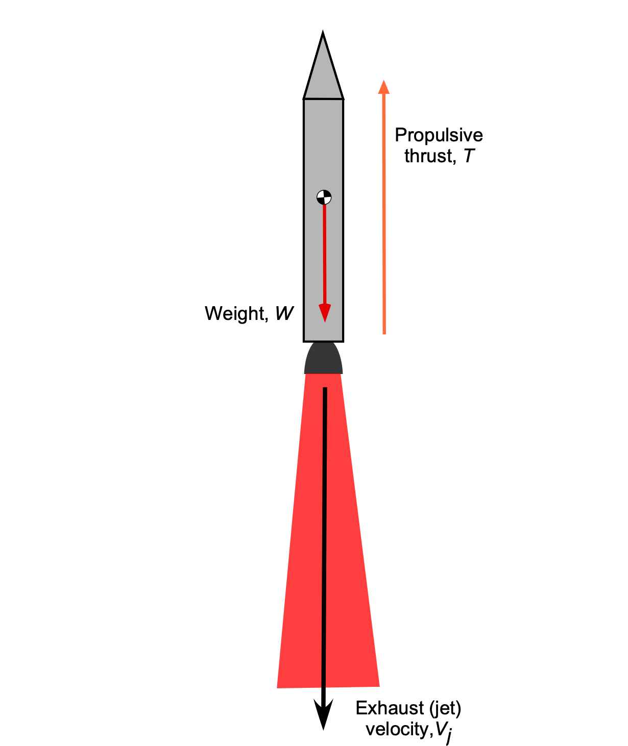
In the case of a rocket engine, a non-air-breathing propulsion system, thrust is produced by expelling high-speed gases, a byproduct of fuel and oxidizer combustion, out of a nozzle, as shown in the figure below. For a launch vehicle, sufficient thrust is required to overcome the vehicle’s weight, provide the payload with the necessary energy, and ultimately accelerate the payload into orbit. In each case, the principles of thrust production must be in accordance with Newton’s laws and the conservation of mass, momentum, and energy.
Learning Objectives
- Distinguish between the basic engine types used to power flight vehicles.
- Learn to distinguish the fundamental differences between air-breathing engines, such as piston engines, turbojets, turbofans, and turboprop engines.
- Understand the basic physical principles of thrust production from air-breathing and rocket engines.
- Know how to determine the efficiency of a propulsive system in terms of specific fuel consumption and specific impulse.
Types of Propulsion Systems
Not all flight vehicles are created equally, and they will require different propulsion systems. An aircraft propulsion system must produce at least enough thrust to balance the drag of the airplane when in flight and drive the aircraft forward at the required flight velocity; drag is typically an order of magnitude less than the aircraft’s weight. However, the thrust produced must exceed the drag of the airplane for it to accelerate to a higher airspeed and/or climb to a higher altitude. Therefore, an aircraft propulsion system must have at least some excess thrust (or power) capability for takeoff, etc., and more than that required for straight-and-level flight. Likewise, the rocket engine(s) on a launch vehicle must create enough thrust to overcome the entire weight of the vehicle initially, then progressively build up sufficient excess thrust as fuel is burned off, enabling the rocket to reach an orbital velocity and altitude.
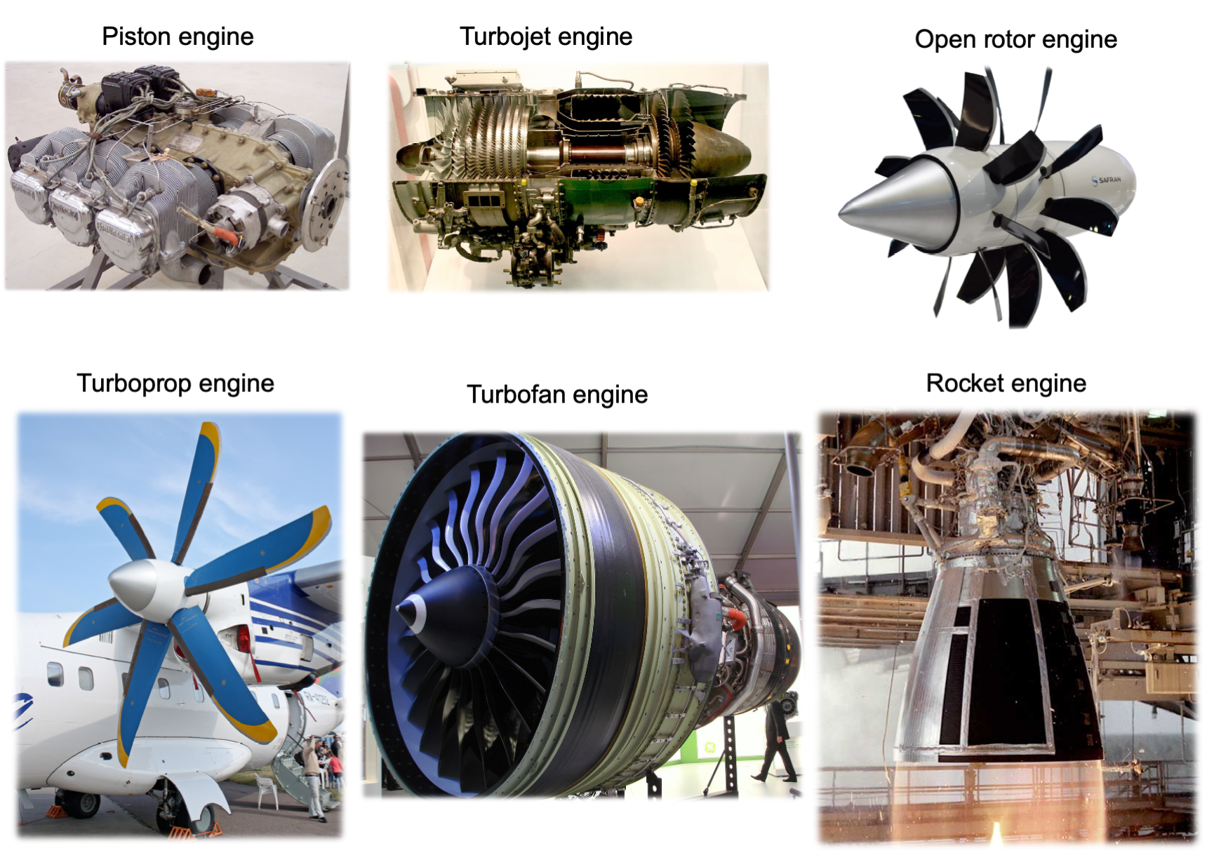
The needed propulsion on a flight vehicle can be achieved using at least one of the following systems, as shown in the images below.
- A propeller and engine combination, such as a reciprocating (piston) engine.
- A turbojet is a basic jet engine that produces pure jet thrust.
- A turbofan is a jet engine with a bypass fan that directs a significant mass flow rate around the engine’s core.
- A turboshaft in which all shaft power goes to a reduction gearbox and transmission system, such as the one used on helicopters.
- A turboprop is a turboshaft engine driving a propeller from a power turbine with little jet thrust.
- The rocket engine, which, unlike the preceding types, is not air-breathing.
Each propulsion system differs in its functional design, but the purpose in each case is to convert fuel into propulsive power and force to propel a flight vehicle. This goal is crucial because, to a large extent, any flight vehicle’s performance capabilities are determined by the thrust generated by the propulsion system and the quantity of fuel required to produce that thrust. As the figure below suggests, the propulsion system for a given aircraft design depends primarily on the vehicle’s intended airspeed or Mach number.
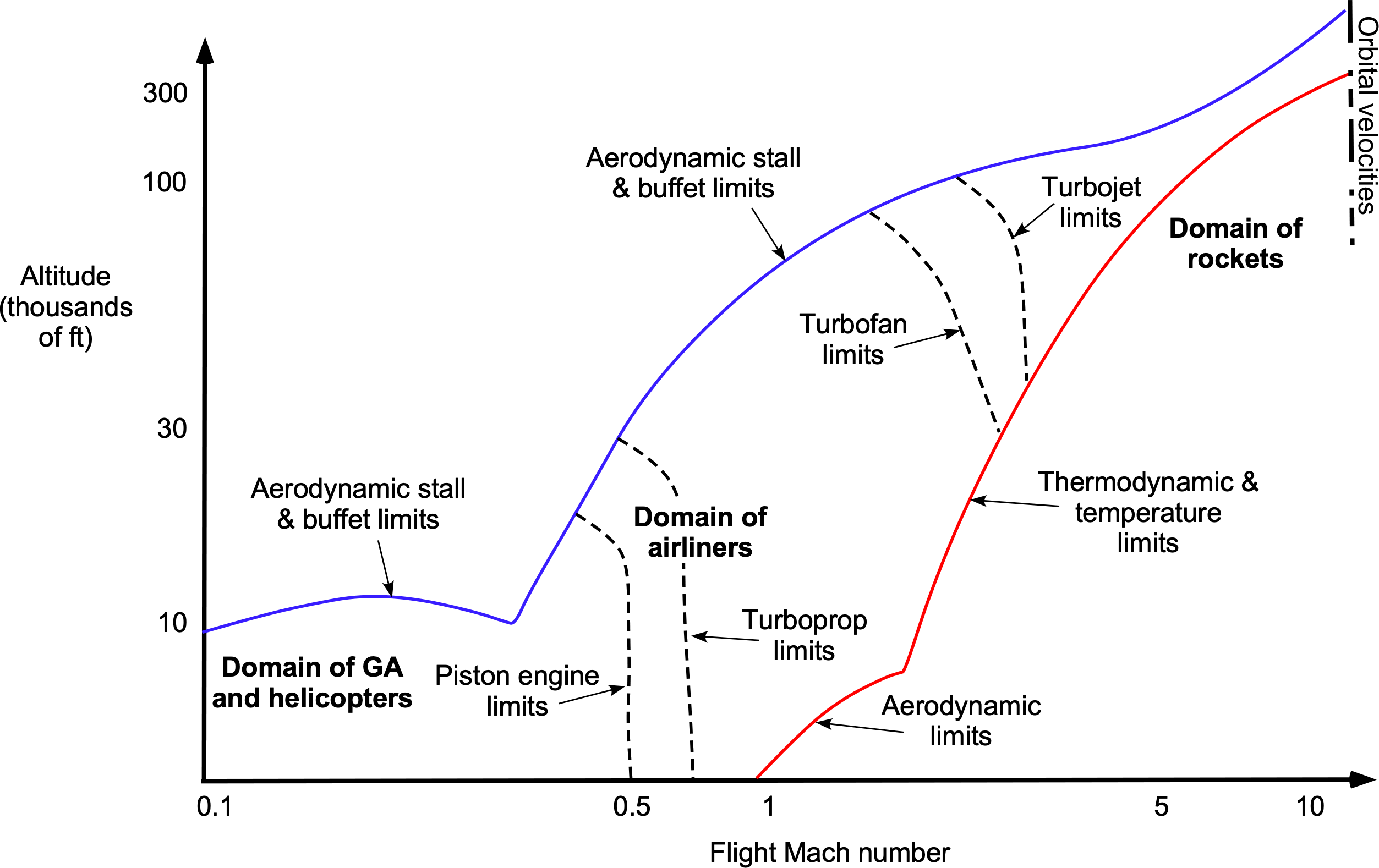
For example, a propeller engine combination or turboprop might power a low-speed transport aircraft. In contrast, a turbojet may power a fighter jet capable of supersonic flight. A piston engine and propeller combination will likely power smaller general aviation airplanes. Turboshaft engines typically power helicopters, although some smaller helicopters may utilize piston engines. Airliners spend most of their flight time at cruise, operating at a single airspeed and with almost constant engine thrust. The high efficiency and relatively low fuel burn of turbofan engines make them attractive for these types of airplanes.
For higher supersonic speeds and flight Mach numbers, turbojets are a viable option. Military airplanes need significant amounts of excess thrust to accelerate quickly, such as during combat maneuvers, and to overcome the high drag associated with operations at transonic and supersonic flight speeds. For this reason, military aircraft must have significant margins of excess thrust. They may also employ afterburners (also known as reheat) to generate a substantial amount of excess thrust, at least for short periods. Compared to air-breathing engines, rockets also typically operate at very high thrust levels as well as high pressures and temperatures, but for relatively short amounts of time.
Piston Engines
A reciprocating piston internal combustion engine driving a propeller is often used to power low- to moderate-performance airplanes. The propeller is directly attached to the engine’s crankshaft, which spins and produces forward thrust, as illustrated in the figure below. The propeller may be of the fixed-pitch type for low-performance airplanes and the variable-pitch (or constant speed) type for higher-performance airplanes.
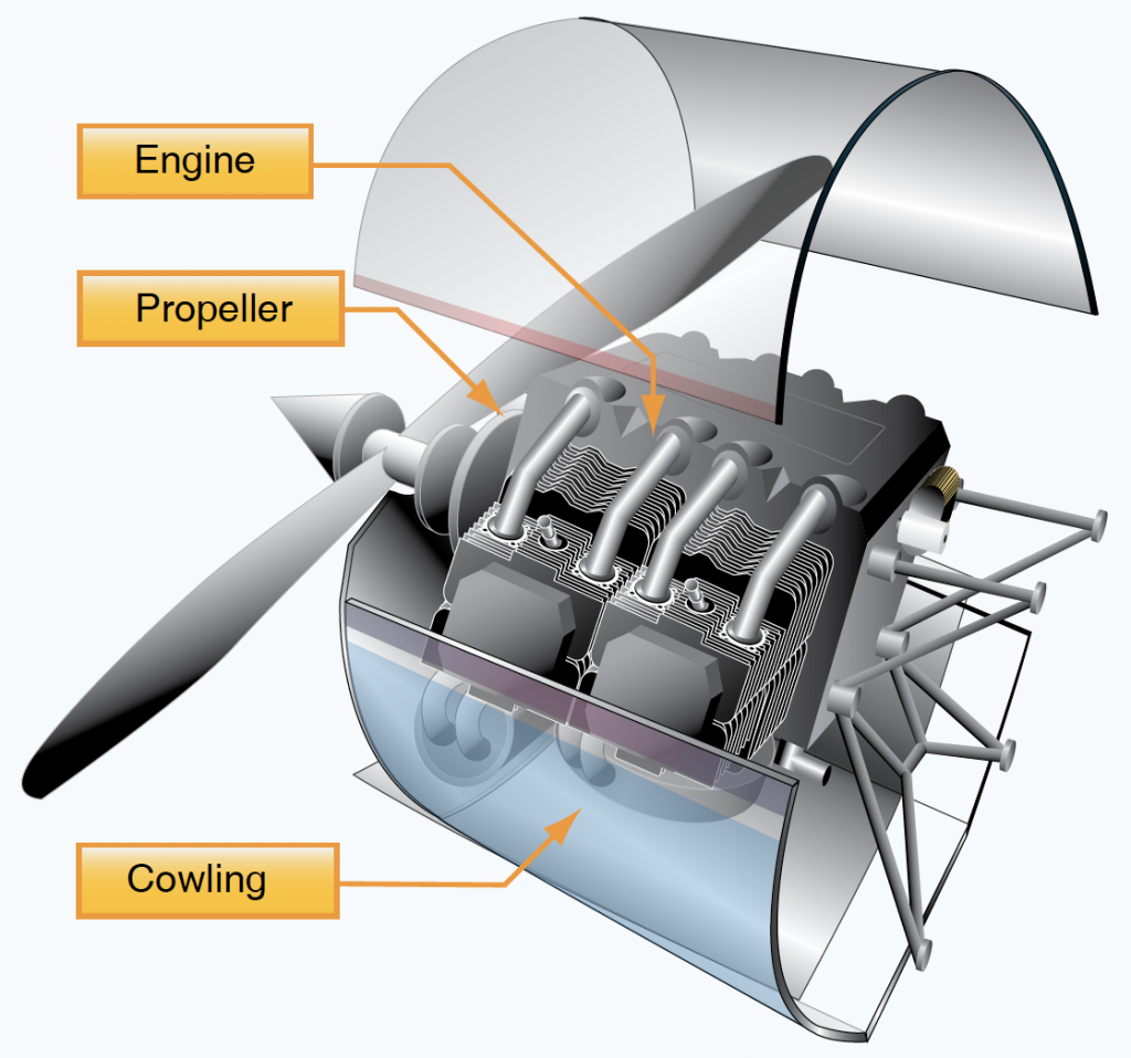
This propulsion system has the advantages of being robust and relatively inexpensive while also providing reasonable propulsive efficiency in terms of combined engine and propeller efficiency. Supercharging or turbocharging may be used to increase the power of a piston engine and maintain its power output at higher flight altitudes.
A modern propeller exhibits excellent propulsive efficiency and relatively low noise levels. However, a piston engine and propeller combination becomes increasingly heavy for larger power outputs and higher altitude operations above 15,000 ft. If a propeller aircraft design is still desired, a turboprop is usually preferred.
Turbojet, Turbofans & Turboshaft Engines
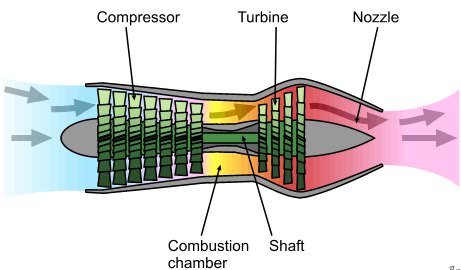
The turbojet, turbofan, and turboshaft are the most frequently confused engine types used on aircraft. In a turbojet engine, as shown in the schematic below, the exhaust gases are expelled at high velocity through a nozzle at the rear of the engine; this process produces all of the thrust by changing the momentum of the flow through the engine. The compressor stage is driven by the turbine stage, which brings the intake air to the pressures and temperatures needed to support combustion.
Turbofan
In a turbofan engine, one or more large fans are mounted at the front, as shown in the schematic below. The fan increases the net mass flow through the engine, resulting in more thrust. However, the fan also expels the flow at a lower exit or jet velocity, which is a more efficient way of producing this thrust. In a turbofan engine, the fan generates a significant portion of the net thrust, approximately 70%, while the remainder comes from the jet thrust developed through the engine’s core and exit nozzle.
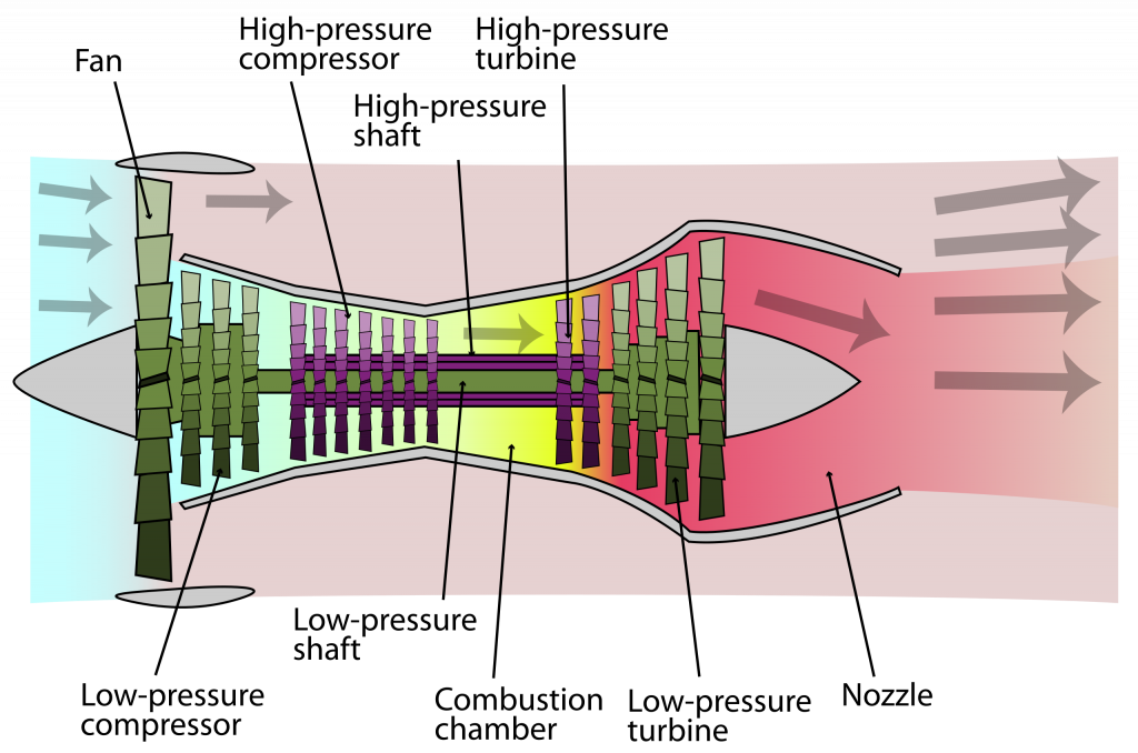
In reference to turbofan engines, the term “bypass ratio” (BPR) is often used, with a higher bypass ratio being more attractive in terms of thrust-producing efficiency. The bypass ratio (BPR) is the area or mass flow through the fan divided by the area or mass flow through the core itself, i.e.,
(1) 
A BPR of 5, for example, means that five units of mass per unit time of air pass through the “cold” bypass stream for every unit passing through the “hot” engine core.
Typical BPR values on modern turbofan engines range from 8 to 11 and have increased progressively over the last three decades through improvements in turbofan engine design. The purpose is clear: it is much more efficient to create thrust by accelerating a large mass flow of air through the fan and expelling it at a lower velocity than by accelerating a lower mass flow of air at a high velocity. For this reason, turbofan engines are more commonly used today than turbojets, for example, on commercial airliners, because of their better efficiency and lower fuel consumption.
Turboprops
Turboprops are closely related to turbofans in terms of operational principle because both transfer energy from a power turbine to do work on a bypass flow stream. As shown in the schematic below, with a turboprop, the turbine stage delivers power to a shaft that drives a propeller. The propeller is often coupled through a gearbox to reduce its speed and prevent the propeller blade tips from reaching supersonic speeds. As a result, there is little energy in the exhaust of this type of engine, so little or no jet thrust is produced.
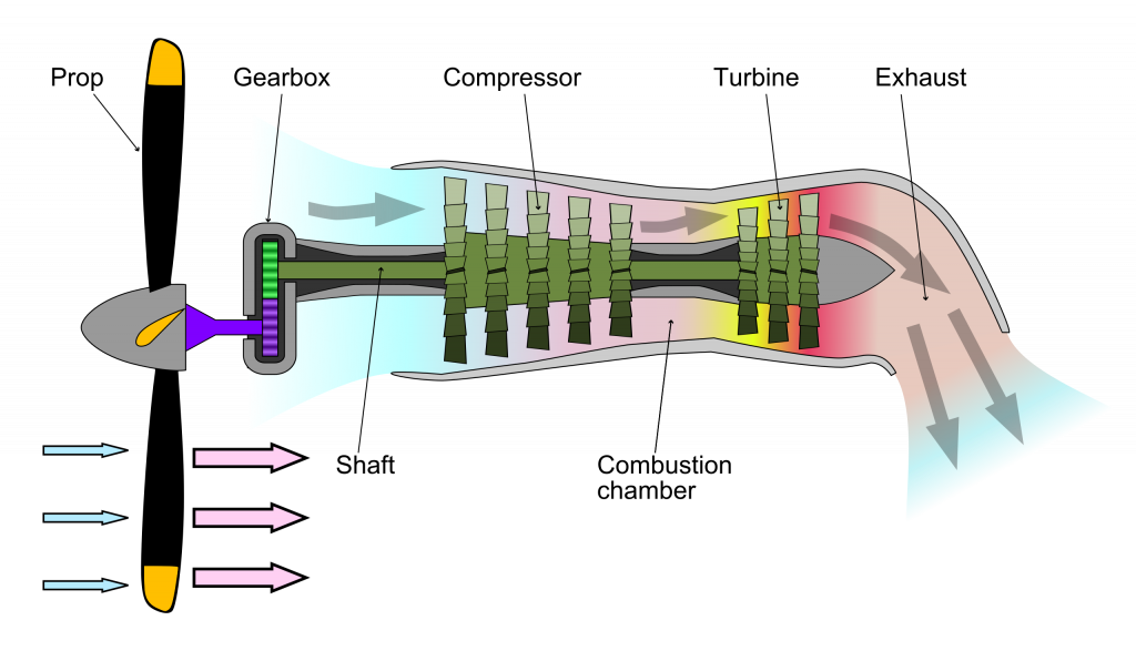
With a turboprop engine, the energy of the hot gases is used to drive a turbine, which in turn drives a shaft to which a propeller is attached. A turboprop is a very efficient way of producing propulsive thrust on an aircraft because it has a very high effective bypass ratio. Nevertheless, the propulsive characteristics of the propeller itself must be carefully considered in relation to the overall system performance, which is typically limited to flight Mach numbers of less than 0.5.
Turboshafts
Turboshaft and turboprop engines are very similar in that both are designed to deliver nearly all of their power to a shaft rather than producing jet thrust, although some small jet thrust may still be produced at the exhaust. The main difference in their design is at the power or compressor turbine stage.
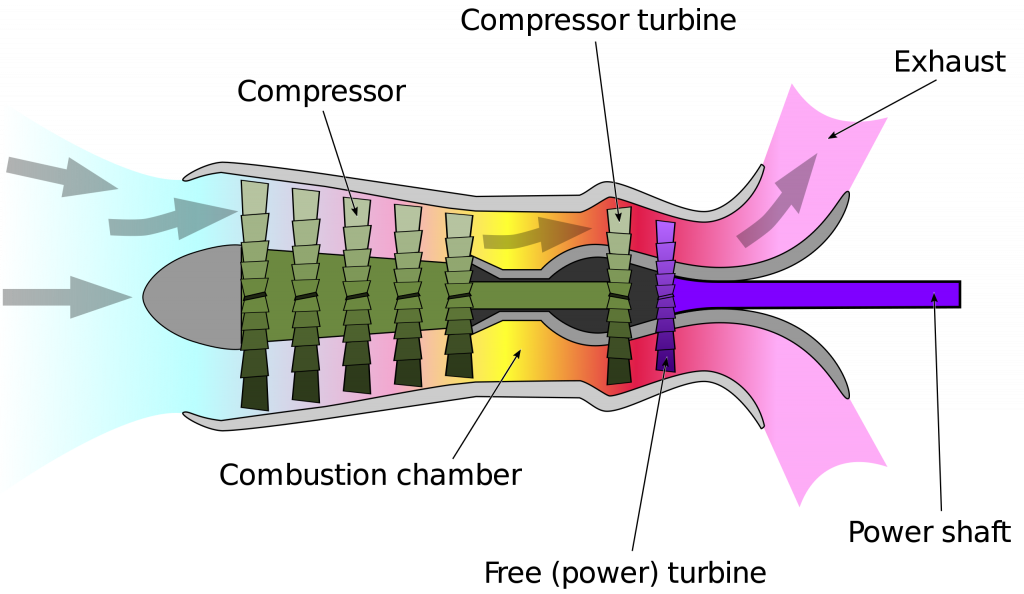
Although in most turboshaft designs, the compressor turbine (gas generator) and power section are mechanically separate, referred to as a free power turbine, as shown in the schematic below, the advantage is that they can rotate at different speeds, each appropriate to the conditions of use. Turboshaft engines are often used to power helicopters but have also been used on tanks and ships.
Air-Breathing Propulsion Fundamentals
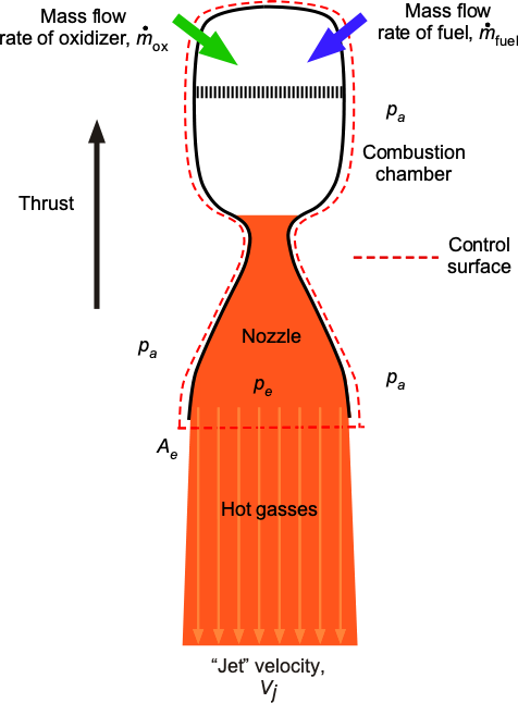
Consider the general propulsive device, as shown by the control volume in the figure below, which moves through the air with an airspeed  . For an air-breathing propulsive device, air is entrained into the front of the device, where it is then compressed and directed to the combustion chambers. Then, the engine utilizes the air (as a byproduct of fuel combustion) to increase its momentum and kinetic energy. Finally, the exhaust is ejected into the slipstream with a higher “jet” velocity
  . In the case of a rocket engine, there is no inlet velocity; however, the operational principles remain the same.
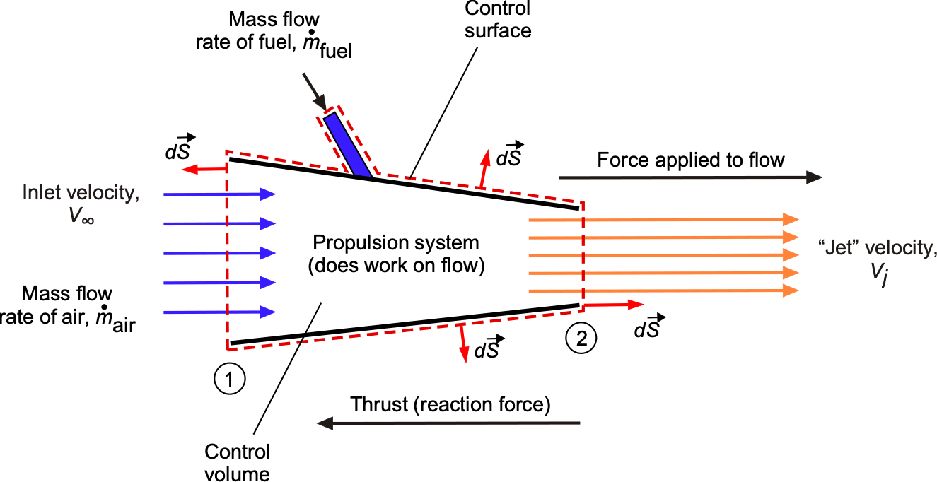
Assume for the following exposition that there are no external pressure forces and that thrust is produced only by the time rate of change of momentum of the flow. If the mass flow of air into the device is denoted by  and the mass flow rate of fuel is
  , then conservation of momentum applied to the flow gives the thrust produced as
(2) 
 then
then (3) 
i.e., the thrust  is equal to the time rate of increase in momentum of the air as it passes through the propulsive device, and so it is proportional to the increase in velocity of the flow
  .
.
The increased velocity of the flow also appears as a gain in kinetic energy, which is irrecoverable, i.e., a power loss, as given by
(4) 
It is clear from Eq. 3 that the production of thrust depends on the mass flow rate moving through the device and how much its velocity increases. So, at least in principle, the same amount of thrust can be generated by accelerating a larger mass of flow but at a smaller jet velocity or by accelerating a smaller mass of flow at a more significant jet velocity, which affects the efficiency of propulsion.
Quantifying Propulsive Efficiency
Generally, a propulsion system’s overall efficiency can be viewed as producing the needed thrust for a given power and the fuel required to produce that power. However, the relative efficiency of the device is essential, i.e., the aerodynamic efficiency of creating a useful propulsive force by doing work on the air.
The efficiency in producing thrust is always related to the kinetic energy of the exit flow from the propulsion system, which is the lost energy per unit time left in the slipstream or wake. Notice that this definition of efficiency does not consider the engine’s thermodynamic efficiency or the aerodynamic efficiency of the actual propulsive device used by the engine to do work on the flow.
Relative Efficiency
In terms of quantifying the efficiency of thrust production, consider the useful power supplied by the device (to propel the aircraft forward at ), which will be the product of the force produced by the propulsive device and the flight velocity (true airspeed) of the aircraft, i.e.,
(5) 
This latter equation pertains to a ground-reference frame; the thrust does no work in the frame moving with the aircraft.
The relative propulsive efficiency can now be defined as
(6) 
which recognizes the losses that appear as a gain in kinetic energy in the downstream jet flow.
Recall that based on the conservation of momentum, the thrust is given by Eq. 3, so substituting in the previous equation gives
(7) 
which, after some simplification, gives
(8) 
where to be meaningful  . Interestingly, matching the exhaust speed and the vehicle airspeed, i.e.,
  , gives the optimum 100% efficiency, at least in theory but not in practice, because Eq. 3 shows that no thrust would be produced in that case.
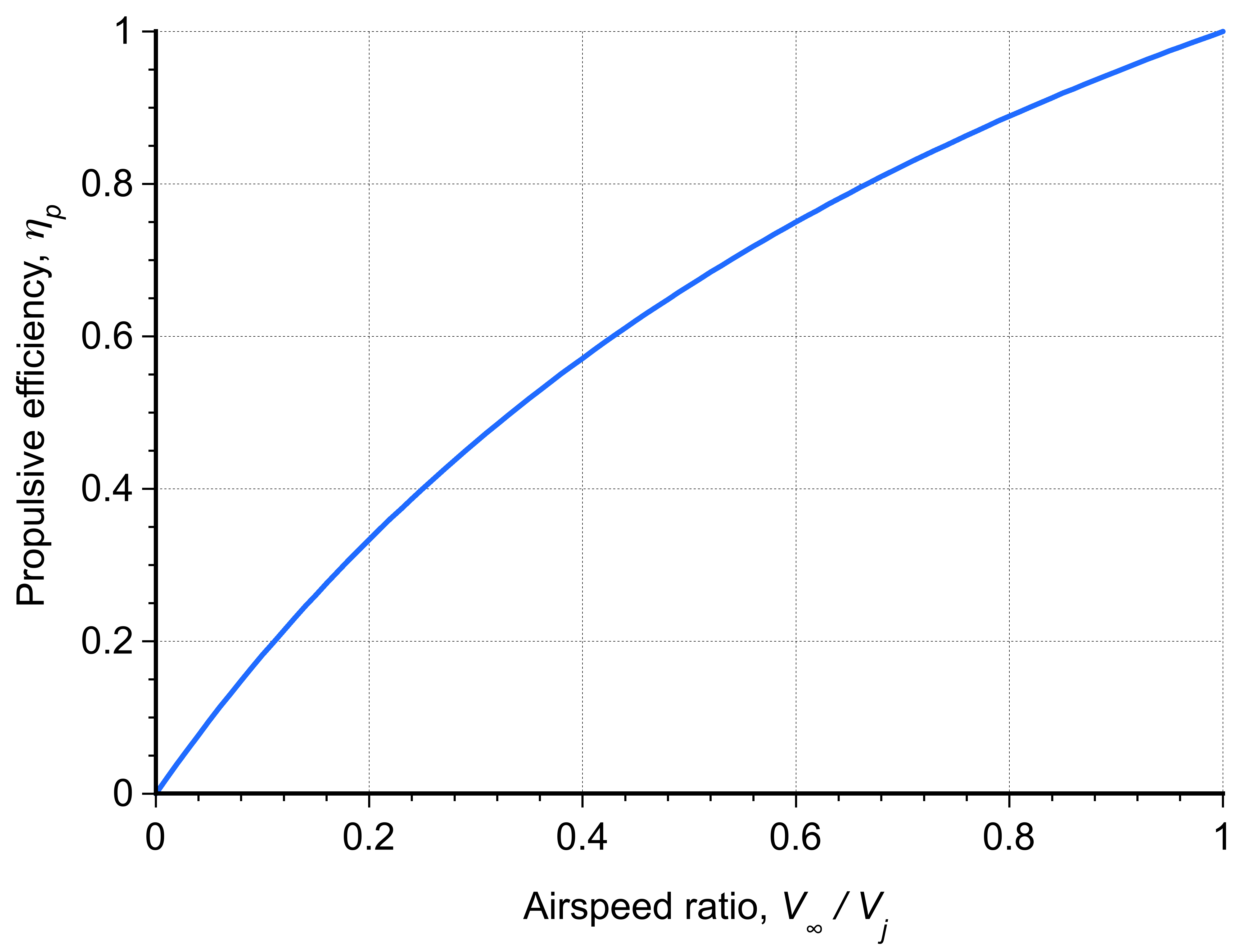
The propulsive efficiency can also be written in a perhaps more intuitive form as
(9) 
by rearranging Eq. 8. This form indicates that propulsive efficiency increases with decreasing jet velocity for a given airspeed, as illustrated in the figure below. This outcome is obtained because the kinetic energy losses become a smaller fraction of the total propulsive power.
Maximizing Propulsive Efficiency
In summary, taking the thrust and efficiency equations together, i.e.,
(10) 
reveals an important outcome regarding the efficiency of thrust production. Notice that a low value of for a given thrust and a higher propulsive efficiency can only be achieved by having a significant mass flow rate,  , through the engine.
Notice also that the thrust equation can be written in terms of specific thrust,  , as
, as
(11) 
The specific thrust (also related to the specific impulse for rocket engines) is a measure of engine efficiency rather than propulsive efficiency.
Different engines will have different values of specific thrust, but those with higher specific thrust values will be more efficient because they produce more thrust for a given mass flow rate. Therefore, yet another form of the efficiency equation is
(12) 
noting that the grouping  is dimensionless.
This result is plotted in the figure below versus  to emphasize the direct effects of mass flow rate. It will be apparent then that for a given airspeed, , the higher the value of the specific thrust and/or the higher the mass flow rate, the better the propulsive efficiency.
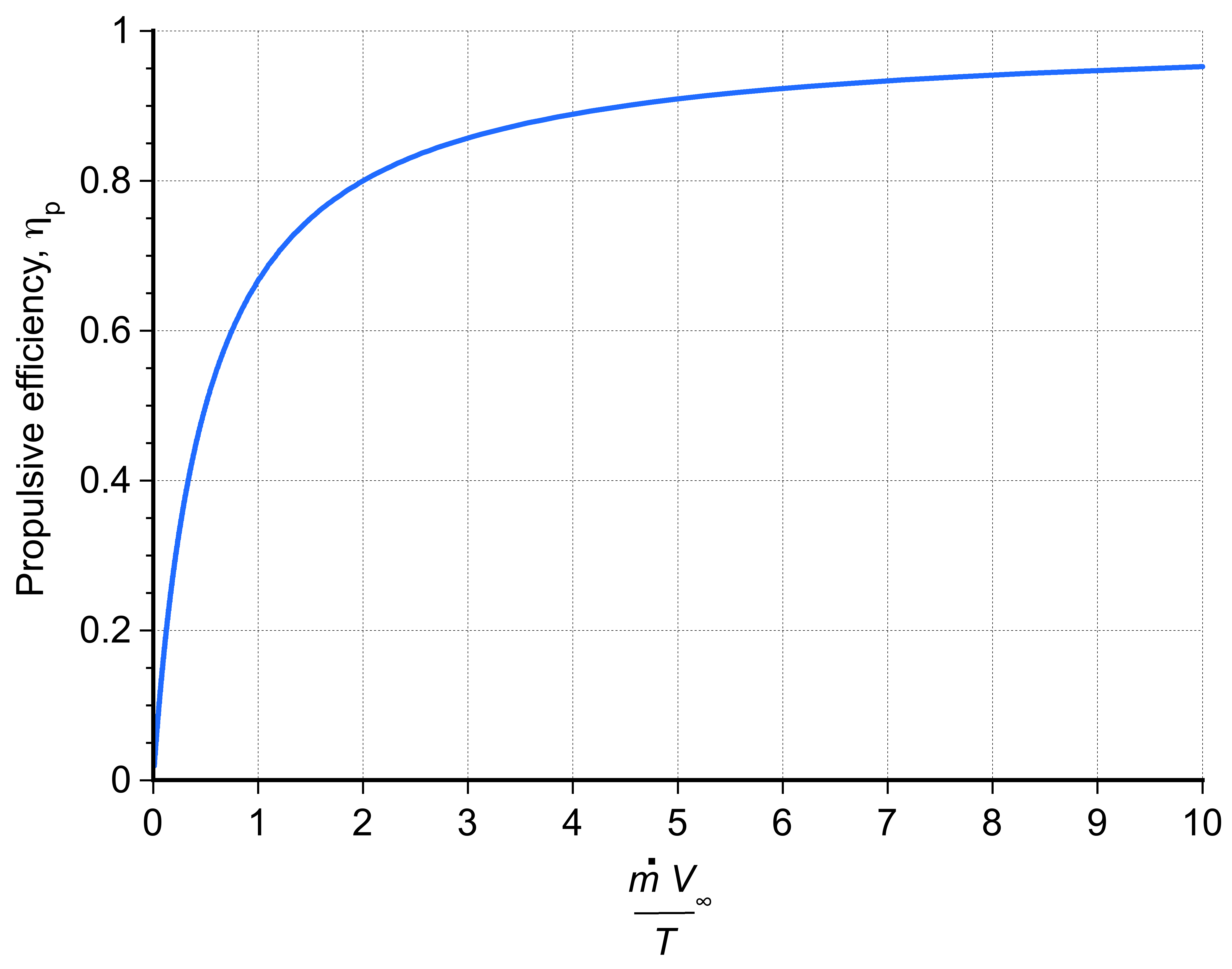
Therefore, it is generally more efficient to create thrust by accelerating a large air volume at a lower jet velocity than a lower air volume at a higher jet velocity. This is why turbofan engines and propellers, which are “high bypass” devices, have the highest levels of propulsive efficiency. Nevertheless, efficiency is always less than 100% as a result of the increased kinetic energy of the exit (jet) flow, an inevitable loss that is a byproduct of creating thrust.
Specific Fuel Consumption
An aircraft’s overall performance characteristics are highly influenced by the engine’s fuel consumption, which can be quantified in terms of specific fuel consumption (SFC). The BSFC (brake-specific fuel consumption) is the fuel weight used per brake unit of power generated, which is a measure of efficiency, i.e.,
(13) 
For turboshaft or piston engines, the shaft power produced must be utilized by a device, such as a propeller or fan, to act on the air; therefore, the propeller or fan efficiency is also considered when determining the overall efficiency of the engine and propeller as a system.
In the case of a thrust-producing engine, the fuel consumption is quantified using thrust-specific fuel consumption (TSFC), which is measured in terms of the weight of fuel used per unit thrust per unit time, again a measure of efficiency, i.e.,
(14) 
Usually, the period for which the TSFC and the BSFC values are quoted is one hour.
To better understand the connection between thrust-specific fuel consumption and efficiency, consider that the overall efficiency of a jet engine is the product of thermal efficiency,  , and propulsive efficiency,
  , with the latter defined as
(15) 
The engine’s useful power output is the thrust power, given by  , and the fuel energy input per unit time is
  , where
  is the heating value of the fuel. Then, the **overall efficiency** is
(16) 
Solving for thrust-specific fuel consumption (TSFC) gives
(17) 
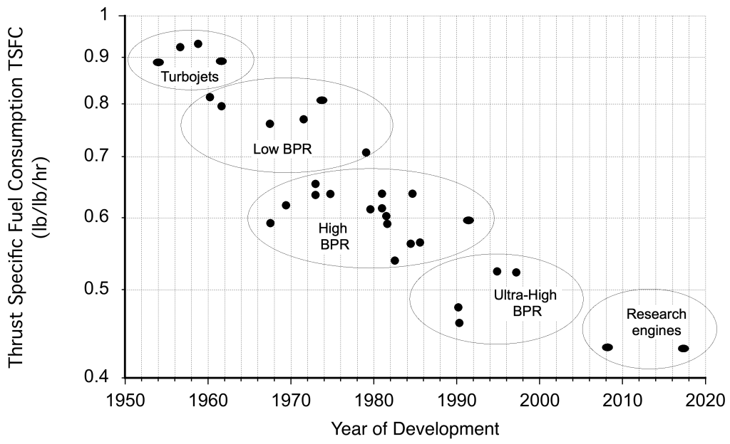
Over the decades of their continuous development, the SFC of aircraft engines has improved (reduced) markedly, as summarized in the figure below. Remember that these values measure engine thrust-producing fuel efficiency, so the reductions shown are significant and commensurate with advances in engineering technology in general.
The efficiency of several propulsive devices is shown in the figure below in terms of their specific fuel consumption, i.e., the fuel used per unit thrust per unit time, which is inversely proportional to propulsive efficiency. Therefore, the higher the efficiency, the lower the specific fuel consumption. Notice that “bypass” increases mass flow through the engine, giving a lower exit or jet velocity. The bypass ratio (BPR) is the ratio of the mass flow through the fan relative to the mass flow through the engine’s core.
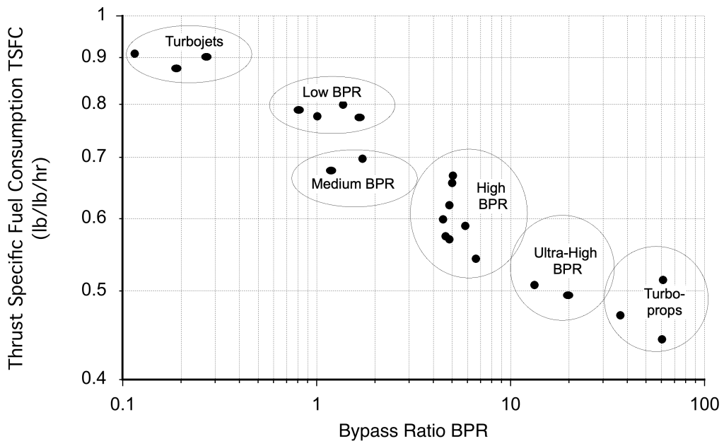
As an example of what has just been concluded in the preceding equations, a turbofan engine (which has a high BPR) has much better fuel efficiency (i.e., lower fuel burn rate) than a turbojet because the fan stage helps to increase mass flow through the engine, but without increasing the net jet velocity () substantially. A higher BPR also helps to decrease jet noise because of the lower values of , where the noise increases quickly with increasing jet velocity. This characteristic is precisely why high-bypass turbofans are used on most modern airliners rather than turbojets; their efficiency exceeds 60%, and they produce relatively low noise.
In fact, by similar arguments, a propeller and engine combination has a higher propulsive efficiency (about 70%) because it produces a high mass flow rate through the propeller, and the downstream is relatively small. On a turbojet, is always relatively high, and the propulsive efficiency of this type of engine may be only 20%.
Nevertheless, it is not always possible to have a propulsion system that is well-suited for the flight conditions in which it operates and is also highly efficient. This issue means that engineers designing new aircraft often have to conduct studies to determine the relative benefits of using one propulsion system over another, depending on the aircraft’s cruise speed and flight Mach number, as well as other design factors. Engineers often call these trade studies, where the relative merits of one concept are traded off against the relative values of another.
Units of BSFC and TSFC
The units of BSFC are typically expressed in lb hp ~hr in the U.S. customary (USC) system, or in kg kW~hr or grams per kilowatt-hour (g/kWh) in the SI system. Notice that in the SI units, BSFC is defined using a unit of mass (kilograms or grams), not weight, which is a well-known anomaly in the SI system. However, in both systems, the time unit is consistently taken as an hour, because BSFC values are commonly quoted in terms of fuel usage per hour of operation.
The thrust-specific fuel consumption (TSFC), by contrast, is expressed in lb lb hr in the USC system or kg kN hr in the SI system. Once again, the SI convention uses units of mass (kilograms) rather than weight (Newtons or kiloNewtons), so care must be taken when interpreting or converting these values. This discrepancy arises from the SI system treating kilograms as a unit of mass, whereas thrust is inherently a force and should ideally be compared with a unit of force. Further caution is warranted because some publications and engine manufacturers may report TSFC using alternative or legacy unit systems, including values per second or per Newton.
Published values of BSFC and TSFC for different engines are typically referenced at the engine’s maximum-rated output (either power or thrust) under standard atmospheric conditions at sea level (ISA). Such values enable meaningful comparisons between engine types, but must be adjusted or interpreted carefully when considering off-design conditions, such as high-altitude or partial-power operation.
| Engine Type | BSFC (g/kWh) | TSFC (lb/lb hr) | Conditions |
|---|---|---|---|
| Piston (reciprocating) engine | 250–300 | — | Sea level, cruise |
| Turboprop | 200–250 | — | Sea level, cruise |
| Turbofan (high bypass, modern) | — | 0.3–0.6 | Sea level, cruise |
| Turbofan (low bypass) | — | 0.5–0.9 | Sea level, military thrust |
| Turbojet (dry) | — | 0.8–1.2 | Sea level, maximum thrust |
| Turbojet (with afterburner) | — | 2.0–3.5 | Sea level, full reheat |
| Ramjet | — | 1.5–2.5 | Supersonic flight, Mach 2+ |
For example, a typical turbojet engine may have a quoted thrust-specific fuel consumption of
![\[ \small \text{TSFC} = 0.035 \ \ \frac{\text{N}}{\text{kN} \, \text{hr}} \]](https://eaglepubs.erau.edu/app/uploads/quicklatex/quicklatex.com-6e3abf1b8ed14a1fc1dce84baed7e87c_l3.svg "Rendered by QuickLaTeX.com")
Because  and
and  , then
![\[ \small \text{TSFC} = \frac{0.035}{1,000 \times 3,600} = 9.72 \times 10^{-9} \ \frac{\text{N}} {\text{N} \, \text{s}} \equiv 9.72 \times 10^{-9} \ \text{s}^{-1} \]](https://eaglepubs.erau.edu/app/uploads/quicklatex/quicklatex.com-61f7fcce1a68caca163d48523ba7bbc6_l3.svg "Rendered by QuickLaTeX.com")
Likewise, a typical turboprop engine may have a quoted brake-specific fuel consumption of
![\[ \small \text{BSFC} = 0.50 \ \ \frac{\text{lb}}{\text{hp} \, \text{hr}} = 0.50 \ \ \text{lb} \, \text{hp}^{-1} \, \text{hr}^{-1} \]](https://eaglepubs.erau.edu/app/uploads/quicklatex/quicklatex.com-cc6d83773371f38e5ee94dfae0135ec1_l3.svg "Rendered by QuickLaTeX.com")
Because  and
and  , then
![\[ \small \text{BSFC} = \frac{0.50}{550 \times 3,600} \ \ \frac{\text{lb}}{\text{ft} \, \text{lb} \, \text{s}} = 2.53 \times 10^{-7} \ \ \text{lb} \, \text{ft} ^{-1} \, \text{lb}^{-1} \, \text{s}^{-1} \equiv 2.53 \times 10^{-7} \ \ \text{ft} ^{-1} \, \text{s}^{-1} \]](https://eaglepubs.erau.edu/app/uploads/quicklatex/quicklatex.com-b3fcf3b22f8f96c2796e7a2498698508_l3.svg "Rendered by QuickLaTeX.com")
Afterburning
A supersonic aircraft generally requires a turbojet engine equipped with an afterburner to generate the additional thrust needed to overcome the sharp rise in aerodynamic drag that occurs in the transonic regime, and to sustain flight at high supersonic speeds. As the aircraft approaches the speed of sound, it encounters compressibility effects and shock waves that dramatically increase drag, a phenomenon commonly referred to as the sound barrier. To pass through this regime, the afterburner injects additional fuel into the jet pipe downstream of the turbine, where it burns in the hot exhaust, as shown in the figure below.
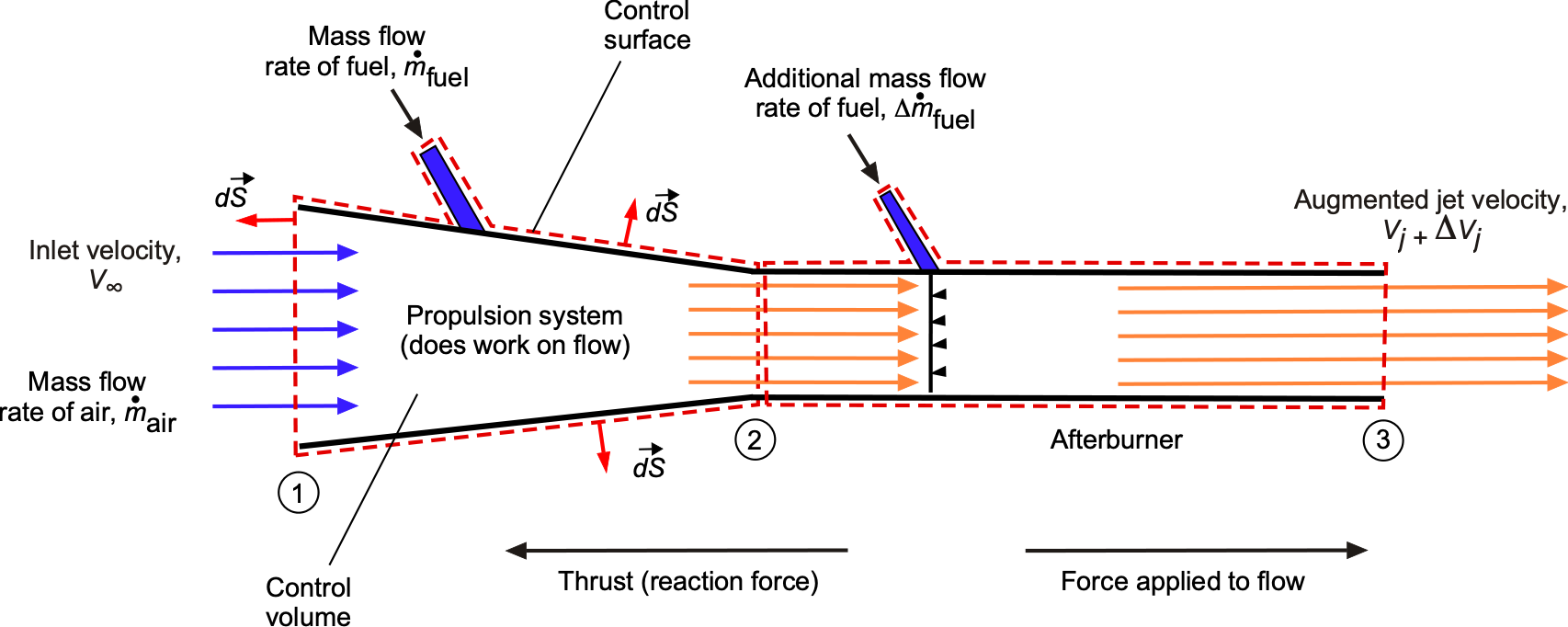
This combustion significantly increases the exhaust velocity from to  , which raises the net thrust from to
  , as described by the momentum thrust relation, i.e.,
(18) 
where denotes the mass flow rate and  is the freestream velocity. If the increase in fuel mass flow rate is neglected compared to the air mass flow rate, so that
  , the thrust equation simplifies to
(19) 
This shows that the additional thrust produced by the afterburner is approximately equal to  , representing the extra momentum gained from the increase in jet exhaust velocity.
The principal advantage of afterburning lies in its simplicity and effectiveness. Afterburning allows for a rapid and substantial increase in thrust without requiring larger compressor stages or a redesign of the engine core. This makes it especially beneficial during combat maneuvers, takeoff from short runways, or when accelerating through transonic drag rise. Afterburners provide thrust augmentation on demand, giving aircraft the ability to exceed the performance limits of dry (non-afterburning) engines. However, this increase in exhaust speed comes at the cost of lower propulsive efficiency. The efficiency with which the engine converts fuel energy into useful thrust is given by
(20) 
This expression shows that as  is added to the jet velocity by the afterburner, then the efficiency decreases significantly.
In summary, taking both the thrust and efficiency equations together reveals an important outcome, i.e., a lower jet velocity for a given thrust results in higher propulsive efficiency, but this can only be achieved with a greater mass flow rate through the engine. Conversely, afterburners rely on raising rather than increasing , which leads to lower propulsive efficiency and so higher fuel consumption.
The implications of this relationship are particularly important when considering afterburning operation. An afterburner increases thrust by injecting additional fuel downstream of the turbine to raise the exhaust velocity from to . While this increases the net thrust , it does so by disproportionately increasing the jet velocity relative to the freestream speed, thereby reducing the propulsive efficiency . According to the relation
(21) 
a large increase in lowers significantly, which, according the inverse relationship in the TSFC expression, then
![\[ \text{TSFC} = \frac{V_{\infty}}{\eta_{\text{th}} \, \eta_p \, h_f} \]](https://eaglepubs.erau.edu/app/uploads/quicklatex/quicklatex.com-890cb8d9f0b9973928c385914a0520b4_l3.svg "Rendered by QuickLaTeX.com")
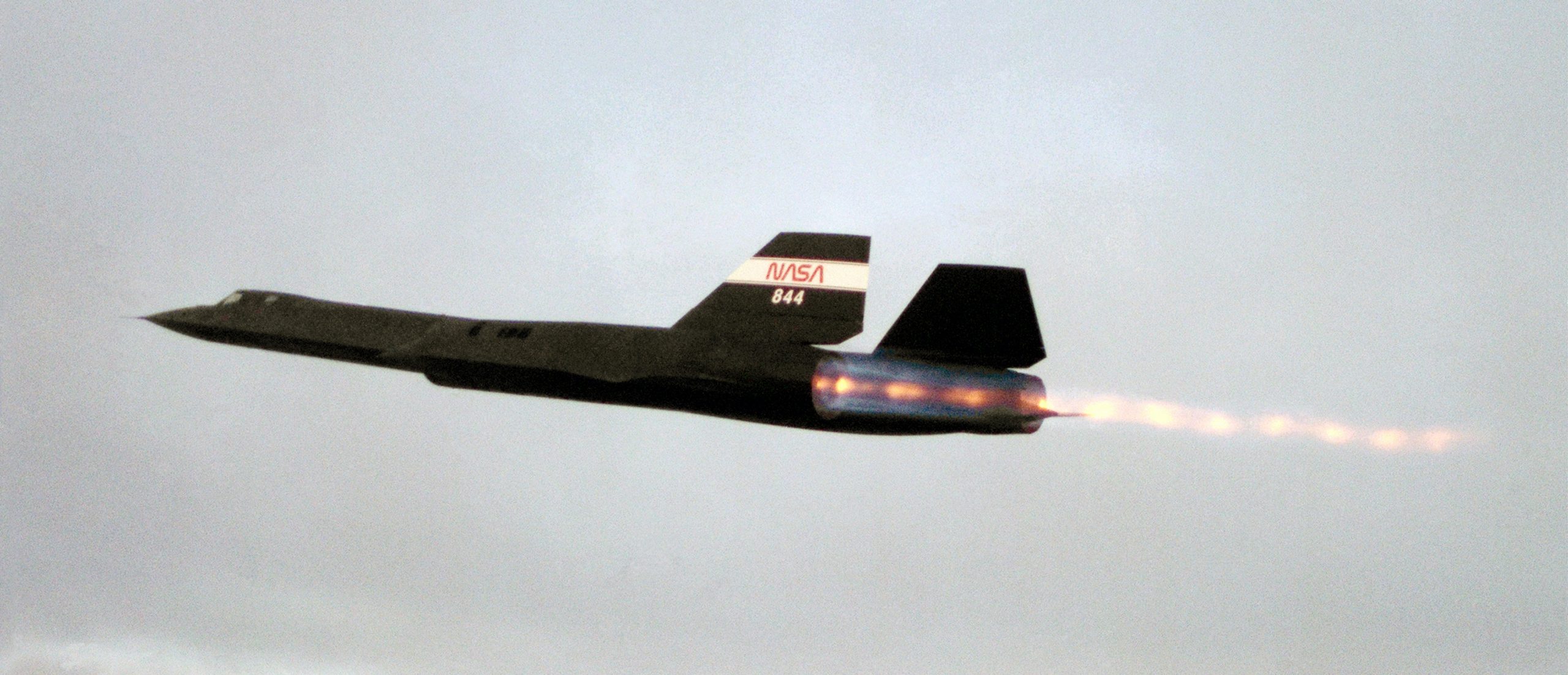
leading to a sharp increase in fuel consumption per unit thrust. In practice, this means that the thrust gained from afterburning comes at the cost of much higher fuel burn. For example, while a turbojet engine might exhibit a TSFC of around 1.0 lb/(lb hr) in dry mode, this value can rise to 2.5 to 3.5 lb/(lb hr) under full afterburner, depending on flight conditions. This is why afterburning is used sparingly, typically for takeoff, transonic acceleration, or combat scenarios, where maximum thrust is prioritized over fuel efficiency. The photograph below shows the SR-71 Blackbird with both engines operating in full afterburner, producing bright exhaust plumes. This configuration enabled the aircraft to pass through transonic drag rise and maintain cruise speeds well above Mach 3.
Check Your Understanding # 1 – Efficiency of propulsion
An airplane’s engine consumes 500 liters of fuel per hour, producing 2,000 N of thrust. The fuel’s energy content is 35 MJ per liter. Calculate the engine’s propulsive efficiency, assuming the airplane flies at a true airspeed of 250 kts.
Show solution/hide solution.
First, calculate the energy input from the fuel consumption using
![\[ \text{\small Energy input} = \text{\small Rate of fuel consumption} \times \text{\small Energy content of fuel} \]](https://eaglepubs.erau.edu/app/uploads/quicklatex/quicklatex.com-db31c828c0432bd7dc657f8407a3be71_l3.svg "Rendered by QuickLaTeX.com")
Convert liters of fuel to energy content in MJ using
![\[ \text{\small Energy input} = 500 \times 35 = 17,500 \text{ MJ/hour} \]](https://eaglepubs.erau.edu/app/uploads/quicklatex/quicklatex.com-d7678a09290db86b2bde5a9883b1ac0f_l3.svg "Rendered by QuickLaTeX.com")
The power output of the engine can be found using the thrust produced and the aircraft’s speed, i.e.,
![\[ \text{\small Power output} = \text{\small Thrust} \times \text{\small Aircraft speed} \]](https://eaglepubs.erau.edu/app/uploads/quicklatex/quicklatex.com-dd8905bf4a283a252e82e6c54ae10664_l3.svg "Rendered by QuickLaTeX.com")
An airspeed of 250 kts is approximately 129.12 m/s (1 knot  0.514 m/s). The useful power output is
![\[ \text{\small Power output} = 2,000 \times 129.12 = 258,240 \text{W} = 258.24 \text{kW} \]](https://eaglepubs.erau.edu/app/uploads/quicklatex/quicklatex.com-5c950df43cb76be0e57bf50b799b8a87_l3.svg "Rendered by QuickLaTeX.com")
The propulsive efficiency,  , is defined as the ratio of the useful power output (propulsive power) to the energy input from the fuel per unit time, i.e.,
![\[ \eta = \frac{\text{\small Power output}}{\text{\small Energy input per unit time}} \]](https://eaglepubs.erau.edu/app/uploads/quicklatex/quicklatex.com-85b2e006de6f2cd919f64d0580ec5bbd_l3.svg "Rendered by QuickLaTeX.com")
Converting all of the numerical values into consistent base units, then
![\[ \eta = \frac{258.24 \times 1,000 \times 3,600}{17,500 \times 10^6} = 53.18\% \]](https://eaglepubs.erau.edu/app/uploads/quicklatex/quicklatex.com-aedba43744e50d703ebae46a6ce1687d_l3.svg "Rendered by QuickLaTeX.com")
Rocket Propulsion Fundamentals
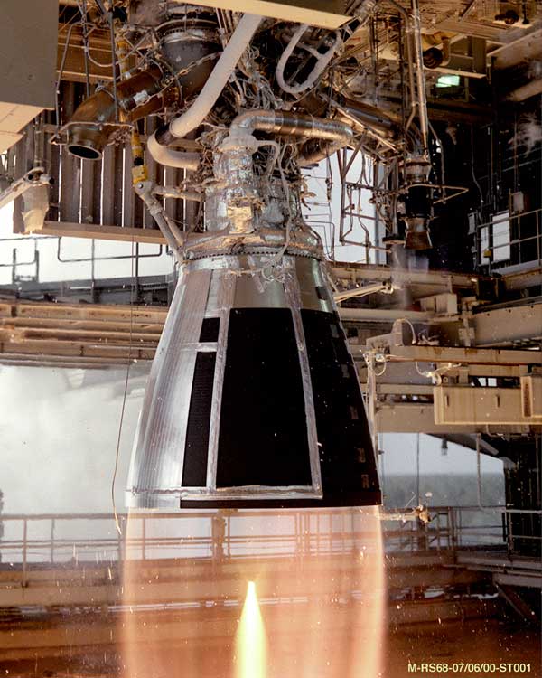
Rocket engines, which are non-airbreathing, are used for spacecraft and launch vehicles; they must carry fuel and an oxidizer during flight. The photograph below shows a rocket engine under test, which uses hydrogen and oxygen as propellants, producing a very clean exhaust and lots of steam.
Rocket engines may also power some types of high-speed aircraft. The first aircraft to break the speed of sound, the Bell X-1, was powered by a rocket engine, as was the first hypersonic aircraft, the X-15. Rocket engines are extremely powerful and operate at high pressures and temperatures, but only for relatively short periods.
The principle of thrust generation for a rocket engine is from the reaction force associated with accelerating a mass of gas at high velocity, the gas being a byproduct of combustion of the fuel and the oxidizer, and so increasing the momentum of the ejected gas. The force on the rocket engine is then opposite to the direction of the gas exit velocity, which is a result in accordance with Newton’s third law. Notice that there is no external ambient mass flow into the engine, such as there would be with an air-breathing engine.
Using the principles of conservation of momentum, the thrust produced by the rocket engine will be
(22) 
where  is the equivalent average exit velocity and is the propellant net mass flow rate; there is no incoming momentum.
Therefore, the higher the mass flow of propellant into the motor and the higher the exit velocity from the nozzle, the higher the thrust will be. Rocket engines typically have incredibly high mass flow rates and exit velocities compared to air-breathing engines. In this case, all of the energy and power liberated to create thrust is manifest as lost kinetic energy, i.e.,
(23) 
Relative Efficiency
The efficiency of thrust production by a rocket engine at a flight velocity can be defined as
(24) 
where is the flight speed.
Using the conservation of momentum, then
(25) 
which, after simplification, gives
(26) 
noting that this is a different result for the efficiency compared to an air-breathing engine, i.e., Eq. 8.
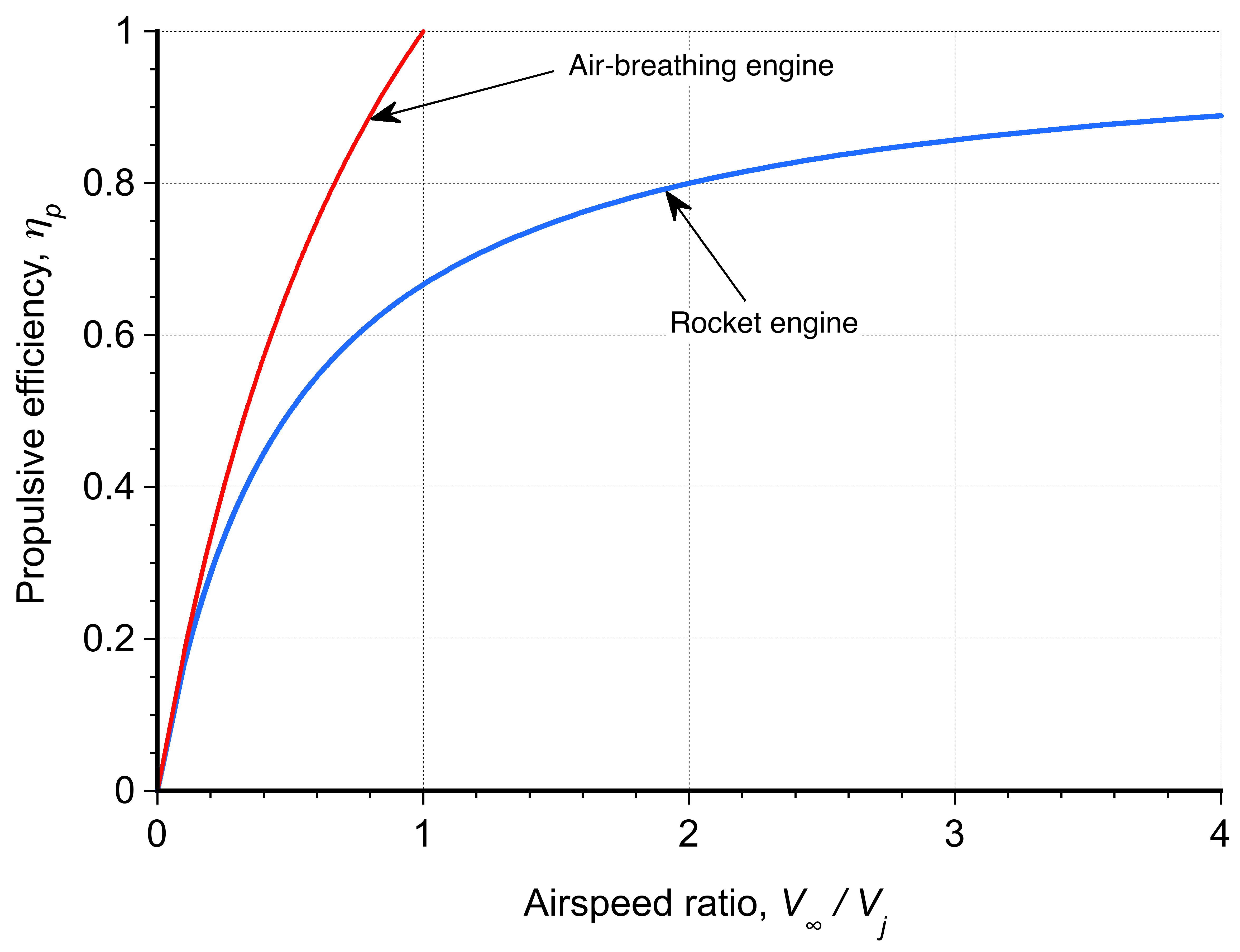
An alternative form of the previous equation is
(27) 
as shown in the figure below. Notice that, unlike air-breathing engines, the flight velocity of rocket engines can exceed their exhaust velocity.
Specific Impulse
In the case of rocket engines, it is customary to define their efficiency in terms of specific impulse,  , which is the thrust produced divided by the flow rate of the weight of propellant, i.e.,
(28) 
where  is the acceleration under gravity at MSL. Notice that has units of seconds, and the specific impulse is inversely proportional to the specific fuel consumption. For rockets, values of typically range from 280 to 465 seconds, depending on the fuel and oxidizer used and the rocket engine design.
Check Your Understanding #2 – Units of specific impulse
Show that the specific impulse has units of seconds.
Show solution/hide solution.
The equation for specific impulse is
![\[ \small I_{\rm sp} = \frac{T}{\overbigdot{m} \, g_0} \]](https://eaglepubs.erau.edu/app/uploads/quicklatex/quicklatex.com-5c92003fe268e4483ed0b0711ab05f94_l3.svg "Rendered by QuickLaTeX.com")
In terms of dimensions, then
![\[ \small \left[ I_{\rm sp} \right] = \frac{\rm M L T^{-2}}{(\rm M T^{-1}) L T^{-2} } = \frac{1}{\rm T^{-1}} = \rm T \]](https://eaglepubs.erau.edu/app/uploads/quicklatex/quicklatex.com-d959c2bc191c6f5ce704116ef9db1ac6_l3.svg "Rendered by QuickLaTeX.com")
Therefore, the units of specific impulse are seconds. Of course, an advantage of this definition is that the numerical value is the same in both SI and USC units.
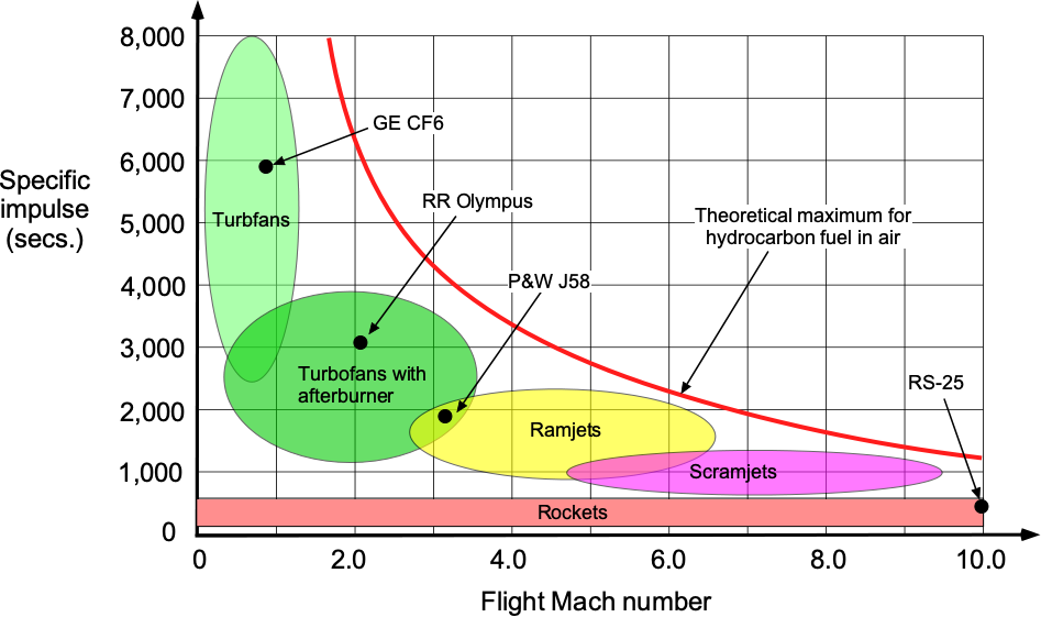
As shown in the figure below, air-breathing engines have a much larger specific impulse than a rocket, typically by one order of magnitude. This latter characteristic is because an air-breathing engine uses ambient air as the oxidizer for combustion, which does not have to be carried. The upshot is lower kinetic energy losses. Therefore, an air-breathing engine uses far less energy to generate a given thrust than a rocket.
As previously discussed, turbofans and turboprops are the most efficient types of air-breathing engines because they accelerate a significant air mass flow rate to a relatively low “jet” velocity.
Electric Propulsion
The engine used to drive an airplane’s propeller is usually a piston or turboshaft engine. However, engineers have been experimenting with electric propulsion systems, including hybrid systems, which use another engine type to augment the electric system.
Compared to a piston or gas turbine engine, an electric motor has certain advantages, including being small, compact, and having relatively few moving parts. It is also relatively inexpensive and quiet compared to an internal combustion engine, and, of course, it produces no emissions and has a smaller carbon footprint. As a point of reference, electric motors will convert about 60% of the electrical energy (obtained from the electrical grid in some form) into usable power. In comparison, conventional engines using fossil fuels (e.g., Avgas or Jet A-1 ) only convert about 20% of the energy stored in the fuel into useful work and power.
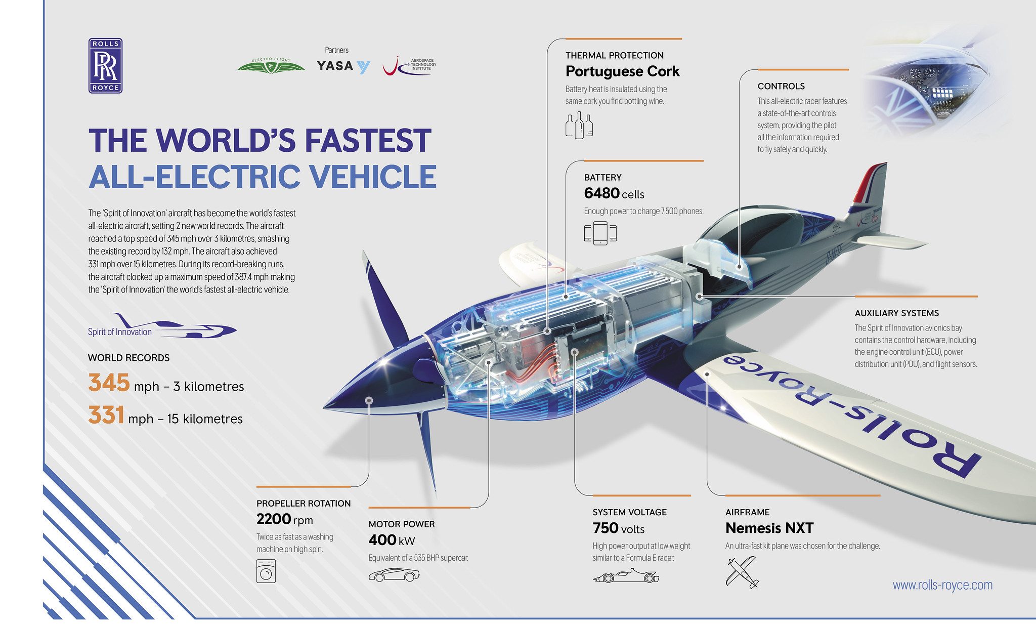
However, using electric engines for aircraft propulsion has many challenges. The main challenge is storing all the energy needed for flight, which requires a lot of batteries, as shown in the figure below. However, batteries are heavy and bulky and must be connected to the motor using heavy cables. Fossil fuels have a much higher energy storage per unit weight, called energy density, compared to what can be stored in batteries, about twenty times. Battery life is also reasonably short because of the chemical and thermal stresses inside the battery induced by the relatively fast discharge cycles associated with the power draw required for flight. Battery packs tend to be expensive to replace, the replacement cycle being significantly shorter than the time between overhauls of an internal combustion engine.
A hybrid propulsion system can give an electric aircraft much greater flexibility. In this case, another type of engine and generator complements the electric system and offers added power when needed. For example, such hybrid systems could be paired with a hydrogen fuel cell, gas turbine, or even a diesel engine coupled to a generator. The consequence is that a hybrid system could give an electric aircraft significantly better flight range and/or endurance, using the hybrid system for takeoff and the smaller electric motors for the cruise. For now, only relatively small electric-powered aircraft, which can fly for up to an hour or so, are feasible.
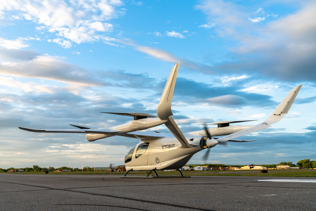
Electric vertical takeoff and landing (eVTOL) aircraft are also being developed to transport goods and people in an urban environment, i.e., as an air taxi for increased urban mobility. The AgustaWestland Project Zero was the world’s first eVTOL aircraft based on a tiltrotor concept. It was developed as a technology demonstrator and was used to investigate all-electric propulsion and other advanced technologies. The photograph below shows another eVTOL concept vehicle with rotors for vertical lift and a propeller for forward thrust. While many such eVTOL aircraft concepts are now being considered, it remains to be seen whether such aircraft will become technically and economically viable. Another concern is how their flight operations, which could be hundreds at one point in time, can effectively and safely integrate into the national airspace system.
Summary & Closure
The production of thrust is essential for all flight vehicles, a glider or sailplane being an exception. A propulsion system consists of an engine of some kind that creates power and work and, hence, a force to propel the vehicle forward. Air-breathing engines include reciprocating piston engines driving a propeller, turboprops, turbojets, and turbofans. In each case, the purpose of the engine is to do work on the air to increase the momentum of the flow and create a reaction force, i.e., the propulsive thrust. Rocket engines are not air-breathing and can operate outside of the atmosphere. However, the principle of thrust generation is the same, i.e., the thrust is equal to the time rate of change of momentum of the gases exiting the engine.
The efficiency of thrust production of an engine is also essential to understand, as it is directly correlated with the quantity of fuel required to produce thrust and the aerodynamic efficiency of the propulsive system. Generally, creating thrust by using more significant mass flow rates and lower exit velocities is more efficient. To this end, turbofans and turboprops are attractive options for powering many airplanes. While electric propulsion concepts for aircraft are still very much in their infancy, they will likely see more widespread use in the coming decades, at least for smaller aircraft or VTOL concepts used for urban mobility.
For Further Thought or Discussion
- In designing a commuter passenger aircraft, consider some design trades in powering the aircraft using turboprops versus turbofans. Hint: Not all of these trades may have an engineering basis.
- Why is the engine used to power a commercial transport aircraft more of what might be called a “point design” versus one used on a military fighter aircraft?
- What are some of the engineering and other issues that might be associated with using an afterburner on a turbojet engine?
- What engine type(s) are being proposed for supersonic business jets?
- What is meant by a hybrid-electric propulsive system? List the relative merits of a hybrid system compared to a pure electric system.
5-Question Self-Assessment Quickquiz
Other Useful Online Resources
To gain a further understanding of propulsion systems, check out these online resources:
- An excellent video with good graphics explaining the differences between engine types.
- To learn more about air-breathing rockets, read How Air-breathing Rockets Will Work.
- For more in-depth information on the Boeing 787 propulsion system, check out this article from AERO Magazine.
- Aircraft engine types and propulsion systems – how do they work?
- A great video on how jet engines work.
- A video explaining future aircraft propulsion systems.
- Electrified aircraft – a video presentation by NASA.
- The reason why aircraft jet engines are so monstrously large today!
- Backyard run of a Rolls-Royce Spey jet engine!
- Great video on how an afterburner works.
