45 Turbojet Engines
Introduction
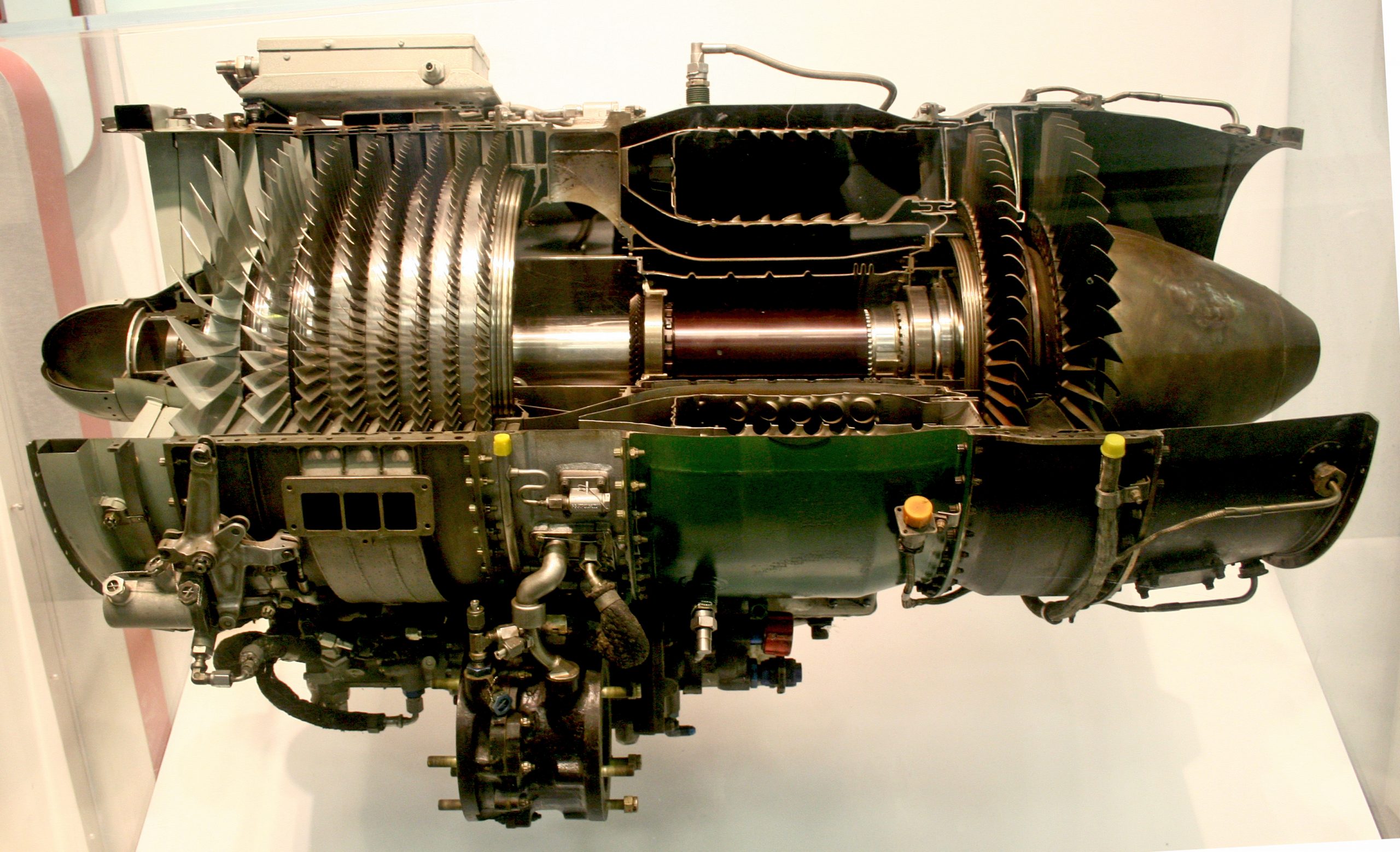
The turbojet is the name used for a gas turbine engine designed to produce thrust by discharging exhaust gases at high speed out of the rear of the engine, i.e., the “jet,” which is done through a suitably shaped propelling nozzle. The turbojet engine, shown in the cutaway example in the photograph below, is used on many aircraft types, particularly those designed to fly at higher airspeeds, including those capable of supersonic flight. Unfortunately, turbojets have relatively low propulsive efficiency at lower airspeeds, limiting their usefulness for high-speed aircraft. Nevertheless, the turbojet has been, and still is, an essential form of propulsion system for various aircraft.
Today, turbojet engines are primarily used in military aviation, powering high-speed fighter jets. Turbojets have also been employed in cruise missiles and certain high-speed unoccupied aerial vehicles (UAVs), providing the necessary thrust for rapid deployment and long-range missions. Experimental and supersonic aircraft, including some research and prototype models, continue to utilize turbojet engines to explore advanced aerodynamics and propulsion technologies.
Learning Objectives
- Learn about the essential components and characteristics of a turbojet engine, as well as its working principles.
- Understand the essential characteristics of a turbojet engine in terms of its thrust production and specific fuel consumption as a function of flight Mach number and operational altitude.
- Appreciate the technique of “afterburning” in a turbojet engine and the various trades in using afterburning engines on an aircraft.
- Learn about a ramjet engine and how it operates.
Design of a Turbojet
The basic design of a turbojet engine is shown in the schematic below. The engine consists of two principal parts: the cold section and the hot section. The cold section includes the air inlet, the compressor stage (driven by the high-pressure turbine), and the compressor-exit diffuser, which slows the compressor discharge flow and distributes it evenly into the combustor. The hot section begins with the combustion chamber, where the compressed air is mixed with fuel and ignited, followed by the high-pressure and low-pressure turbines. The exhaust is then expanded through the propelling nozzle, where it is accelerated to a relatively high jet velocity, providing propulsive thrust by increasing the rate of change of the net flow’s momentum, i.e., the momentum of the air together with the hot combustion products. Although the diffuser hardware is physically attached to the combustor module, it is usually considered a functional part of the cold section because it precedes fuel addition and combustion.
 and
and  process diagrams of the idealized Brayton cycle.
Operational Principle
The operational principle of a turbojet engine is straightforward to understand, as shown in the figure below. The thermodynamic operation of a turbojet follows the Brayton cycle. There are five primary stages:
1. Air intake stage. The intake stage, located in front of the compressor, slows the air down, slightly increasing its static pressure. By design, the airflow speed into a turbojet engine’s compressor must be subsonic, regardless of the aircraft’s airspeed. In supersonic flight, a diverging duct with doors and/or baffles can reduce the incoming flow to subsonic conditions.
2. Compressor stage. The flow is then directed onto the vanes and the spinning compressor blades, where progressively higher pressure increases are produced. Older turbojet engines had fixed vanes (stators) before the moving blades. However, modern engines have stators with variable pitch to direct the oncoming air onto the compressor blades at the appropriate angles based on the engine’s operating state and flight speed. Notice that the high-pressure turbine drives the compressor through a forward-facing shaft in the hot stage.
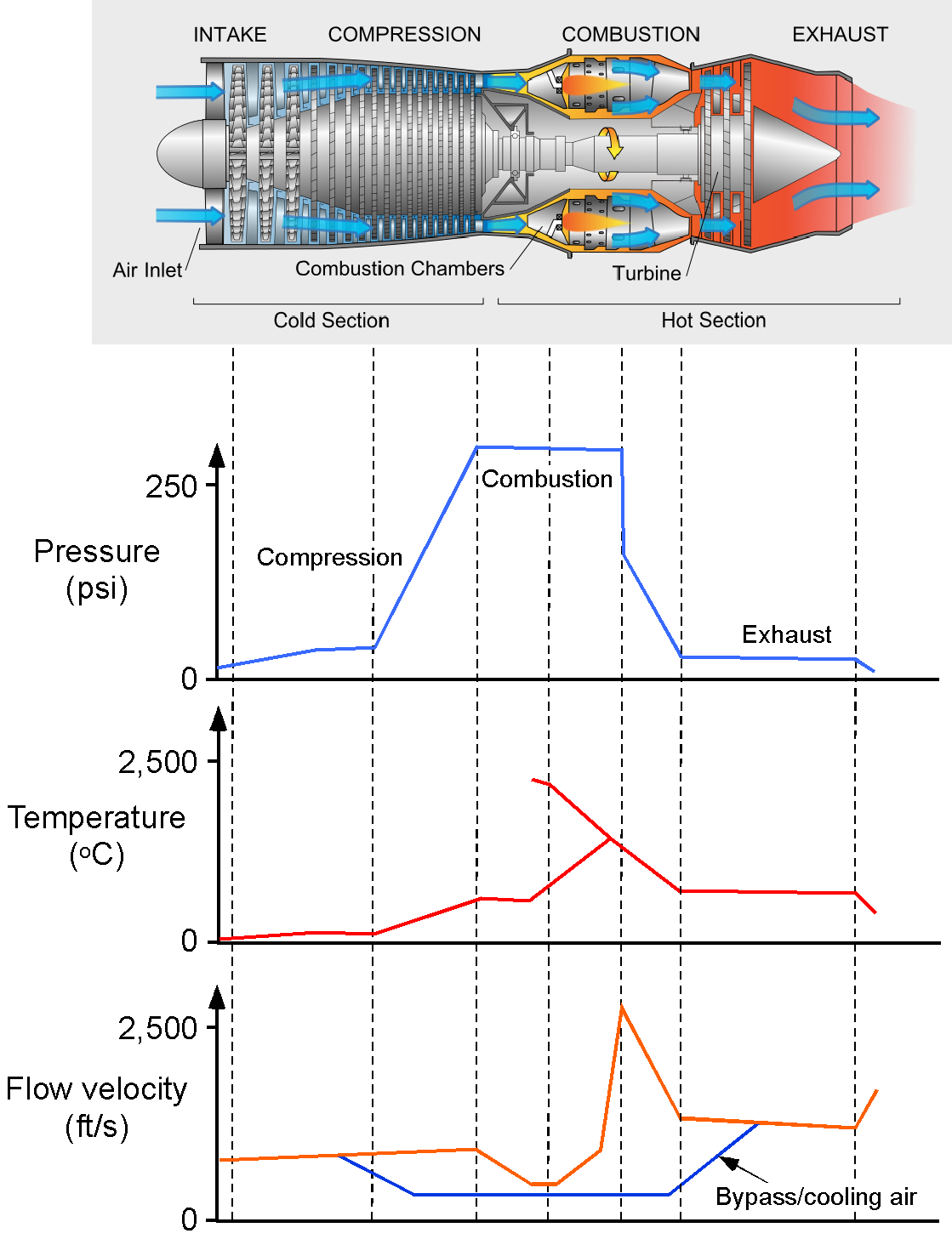
3. Combustion stage. The fuel is burned in the combustor to produce a gas flow at a much higher temperature. This process is a continuous, nearly constant-pressure process, which differs from the combustion process in a piston engine. As the fuel burns, the pressure in the confined region above a piston increases rapidly. This flow then passes into the gas generator turbine.
4. Gas generator turbine stage. This stage rotates relatively faster than the compressor stage, significantly adding kinetic energy to the airflow. Notice that compressing the air increases both its pressure and its temperature. Additional air from the compressor is bled into the region downstream of the combustion chambers through a bypass circuit. This reduces the temperature of the hot gases, allowing turbine blades in the power stage to withstand them safely without burning or melting. The hot-stage high-pressure and low-pressure turbine blades are made of special steel alloys that can sustain extremely high temperatures. Nevertheless, the turbine vanes and blades require internal cooling passages to maintain acceptable material temperatures.
5. Exhaust stage through a nozzle. After the turbine, the gases expand through the exhaust nozzle, producing a high-velocity jet that serves as the primary source of thrust. One problem with this high-speed flow from a turbojet engine is that it creates significant noise. Research has shown that the increase in noise is approximately proportional to the fully expanded exit velocity,  , i.e.,
(1) 
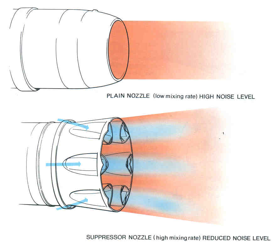
where  = 8 for subsonic jet conditions is called the eighth-power law, and = 3 for supersonic jet conditions is called the third-power law. These are both empirical laws, i.e., based on actual measurements of jet noise. As shown in the figure below, most turbojet engines use noise suppression devices such as corrugated or lobe-type suppressors. Such devices alter the turbulent mixing in the jet so that the resulting jet flow sounds quieter to an external observer.
Basis of Thrust Production
The thrust produced by a turbojet engine can be examined using conservation principles of fluid dynamics applied to a control volume surrounding the engine, as shown in the figure below. The basic principle of operation is that air enters and is then compressed to a level that supports combustion, with the energy used to drive the compressor. The exhaust gases exit at high speed, producing the thrust.
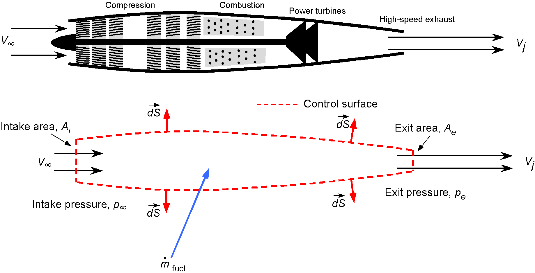
The mass flow of air into the intake of the engine will be
(2) 
where  is the inlet area, and the mass flow rate of fuel is
  . Therefore, using conservation of momentum, the thrust produced,
  , is
, is
(3) 
where  is the exit area and
  is the exit or “jet” velocity, usually given the symbol . The pressure (second) term in Eq. 3 is relatively small compared to the change in momentum of the flow, and so in practice, it may be neglected, i.e.,
(4) 
Notice that the thrust decreases when  increases because depends on both the compression and the combustion, so the difference
  decreases. However,
  increases with increasing , and so the value of thrust depends weakly on at low Mach numbers but more so at higher Mach numbers.
For a turbojet engine at subsonic Mach numbers, it is found that stays relatively constant with . Thrust increases with Mach number at higher flight Mach numbers but lapses with altitude, as shown in the figure below. A jet engine’s “Uninstalled Thrust” is typically determined during static tests on a test stand. The engine is calibrated to relate thrust to parameters such as speed, pressure ratio, and exhaust gas temperature. These parameters are also displayed on the pilot’s cockpit instrument panel. In conjunction with information in the aircraft flight manual, it can be used to calculate the aircraft’s anticipated performance.
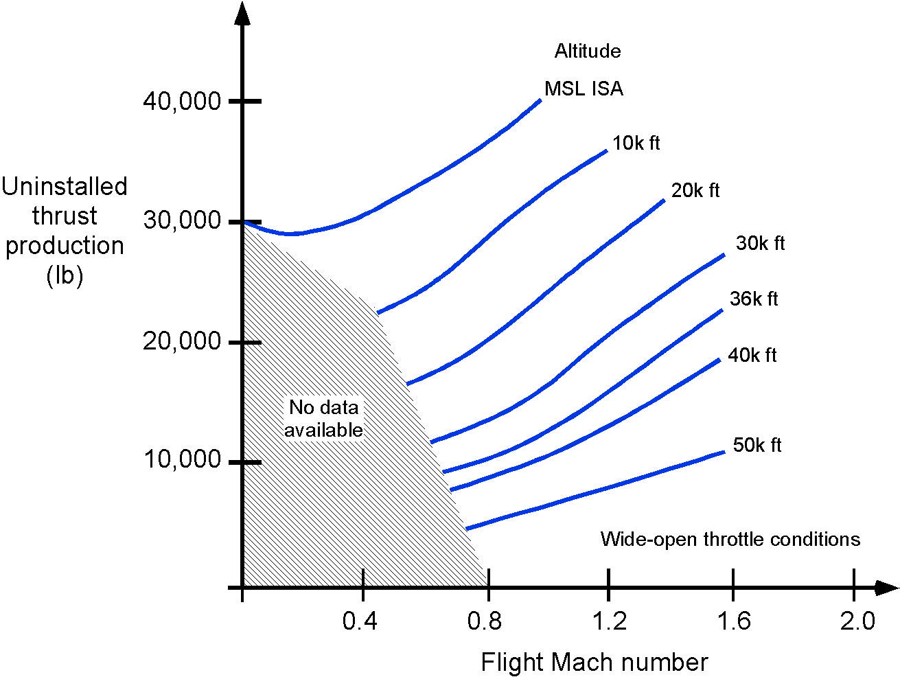
The overall thrust characteristics of a turbojet depend significantly on the flight Mach number and the operational altitude. Again, remember that when speaking of “altitude,” it generally refers to density altitude, i.e., the altitude corresponding to the local ambient density when measured according to the International Standard Atmosphere (ISA). In particular, the maximum thrust is influenced by ambient temperature, with thrust decreasing as temperature increases. This means that on hot days, an airplane may require a longer runway for takeoff than on cooler days.
Engine manufacturers provide a rated thrust value that is guaranteed for use in the airplane’s flight manual. This rated thrust is often “flat-rated,” meaning it is a single value based on the highest ambient temperature that the engine can withstand without exceeding its limits. It is determined by analyzing static engine test data and, if applicable, flight test data.
One approximation for the thrust produced by a turbojet engine is that it increases linearly with flight Mach number according to
(5) 
where  is the lowest Mach number for which the thrust is known, and
  is a constant. The thrust will also decrease with altitude according to
(6) 
where  is the thrust produced at MSL conditions, and the density ratio
  is the density at altitude relative to the density at MSL. The air density can be estimated using the ISA equations, which are based on the local ambient pressure (i.e., pressure altitude) and outside air temperature.
Check Your Understanding #1 – Estimating the thrust produced by a turbojet
Consider a turbojet-powered airplane flying at a pressure altitude of 30,000 ft at ISA standard conditions. The airplane’s true airspeed is 500 kts. The engine has an inlet area, , of 0.7 m . The velocity at the exit, , is 463 m/s. All velocities are measured relative to the engine’s reference frame. Estimate the thrust of the turbojet and the equivalent power it produces. Neglect the mass of fuel entering the engine and all effects of pressure differences.
Show solution/hide solution.
The thrust, , of the engine can be expressed as
![\[ T = \overbigdot{m} \left( V_e - V_{\infty} \right) + \left(p_e \, A_e - p_i \, A_i \right) \]](https://eaglepubs.erau.edu/app/uploads/quicklatex/quicklatex.com-053715b83c08a24d545fae52d8112462_l3.svg "Rendered by QuickLaTeX.com")
where
![\[ \overbigdot{m} = \varrho_{\infty} \, A_i \, V_{\infty} \]](https://eaglepubs.erau.edu/app/uploads/quicklatex/quicklatex.com-950fea6162980a56fc96011c9a3363e4_l3.svg "Rendered by QuickLaTeX.com")
At 30,000 ISA standard conditions,  = 0.4583 kg/m
 . The flight velocity is 500 knots, which is equivalent to 257.2 meters per second. Hence, the mass flow into the engine is
![\[ \overbigdot{m} = \varrho_{\infty} \, A_i \, V_{\infty} = 0.4583 \times 0.7 \times 257.2 = 82.51~\mbox{kg/s} \]](https://eaglepubs.erau.edu/app/uploads/quicklatex/quicklatex.com-fc3709a15da0d4eafa57e44462908b92_l3.svg "Rendered by QuickLaTeX.com")
In this case, we are told to neglect the pressure difference effects, so the thrust, , from the engine is equal to the time rate of change of the momentum of the flow as it goes through the engine, i.e.,
![\[ T = \overbigdot{m} \Delta V = \overbigdot{m} \left( V_e - V_{\infty} \right) \]](https://eaglepubs.erau.edu/app/uploads/quicklatex/quicklatex.com-38511a6cf359a115076cf655f4b8abc9_l3.svg "Rendered by QuickLaTeX.com")
Inserting the numerical values gives
![\[ T = 82.51 \left( 463.0 - 257.2 \right) = 16.98~\mbox{kN} \]](https://eaglepubs.erau.edu/app/uploads/quicklatex/quicklatex.com-2fd2c4169c65301799ecd88e29d4e180_l3.svg "Rendered by QuickLaTeX.com")
The equivalent power produced by the engine,  , is given by
![\[ P_{\rm eq} = T V_{\infty} = 16.98 \times 10^3 \times 257.2 = 4.27~\mbox{MW} \]](https://eaglepubs.erau.edu/app/uploads/quicklatex/quicklatex.com-cef746a68425b03c34730d58ecbe8a03_l3.svg "Rendered by QuickLaTeX.com")
Thermodynamics
The Brayton cycle is the fundamental thermodynamic model for gas turbine engines, which power most of modern aviation in the form of turbojets, turbofans, and turboprops. First proposed in the 1870s by George Brayton, the cycle became practical only with the development of axial compressors and turbines in the 20th century. It remains central to propulsion because it illustrates how chemical energy in fuel is converted into either a high-velocity exhaust jet (as in turbojets) or mechanical shaft work (as in turbofans and turboprops) to produce thrust.
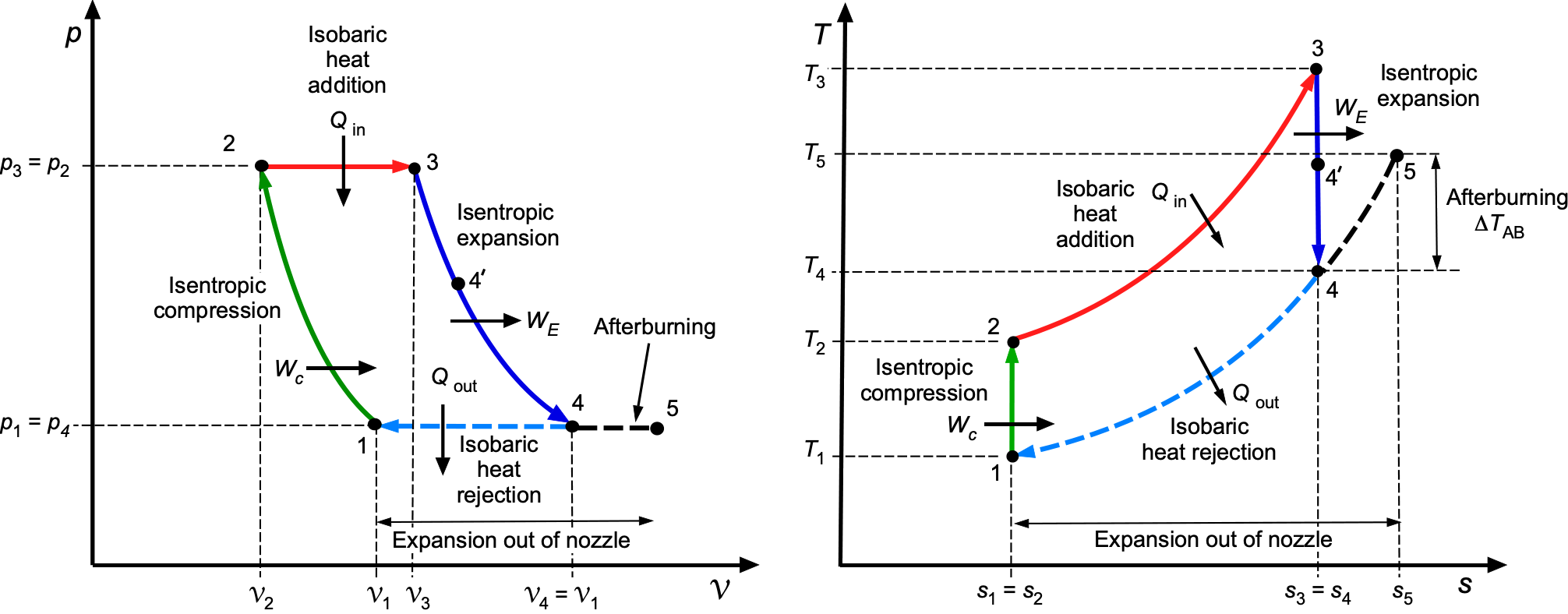
The ideal Brayton cycle consists of four internally reversible processes, as shown in the schematic below. The first process (1 to 2) is isentropic compression in the compressor. The second (2 to 3) is constant-pressure heat addition in the combustor. The third (3 to 4) is isentropic expansion through the turbine, producing work. The final process (4 to 1) is constant-pressure heat rejection, representing discharge to the atmosphere.
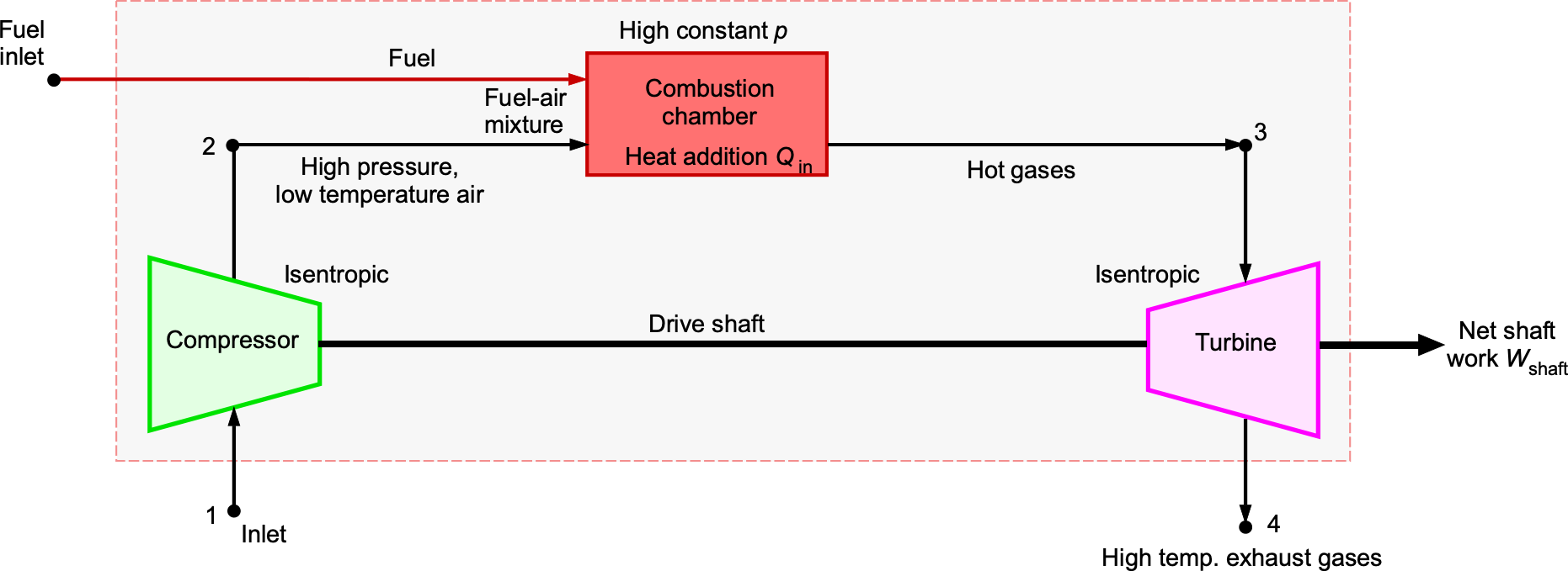
Although a gas turbine operates as an open system, it is often represented as a closed thermodynamic loop so that the cycle can be analyzed consistently using and diagrams. In this representation, the notional process from state 4 to 1 corresponds to heat rejection to the surroundings, conceptually closing the cycle.
and process diagrams of the idealized Brayton cycle.The heat interactions are
(7) 
and the work is
(8) 
so that  From the isentropic relations, then
(9) 
where  is the compressor pressure ratio. Substituting gives the thermal efficiency as
(10) 
Therefore, the Brayton efficiency improves with increasing pressure ratio and turbine inlet temperature, subject to the practical limits of compressor design, materials, cooling, and weight.
In a gas turbine cycle, the turbine must supply enough work to drive the compressor and provide useful net work for propulsion through a jet from a suitably shaped nozzle or as shaft power. The turbine’s work output is
(11) 
and the compressor work input is
(12) 
so that the net cycle work is
(13) 
The fraction of the turbine work consumed by the compressor is called the back-work ratio (BWR). It is defined as
(14) 
A high back-work ratio (BWR) indicates that a significant fraction of the turbine output is internally used to drive the compressor, leaving less net work available. On the diagram, this is shown by dividing the turbine expansion into two parts: the segment from state 3 to 4′ supplies exactly the compressor work, while the segment from 4′ to 4 represents the net turbine work output. In modern gas turbines, the BWR is typically 40–60%. Because the compressor consumes a large portion of the turbine work, gas-turbine performance strongly depends on achieving high turbine inlet temperatures. Hotter turbine entry conditions provide more expansion work to meet compressor demand and still produce useful net power.
In turbojets and turbofans, the turbine extracts just enough work to drive the compressor (and fan), leaving most of the remaining enthalpy to expand through the nozzle and produce thrust. The resulting BWR is high, typically 0.45–0.55, meaning that nearly half of the turbine work is internally recycled, with only the remainder producing jet power. In contrast, turboshaft and turboprop engines must supply significant shaft power in addition to running the compressor, so they operate with much lower BWR values, typically 0.2–0.3.
Thrust-Specific Fuel Consumption (TSFC)
The output of a turbojet is thrust, so the specific fuel consumption is based on the amount of thrust produced. Recall that the specific fuel consumption is based on the shaft or brake power for engines that primarily produce shaft power (e.g., a piston engine or a turboshaft engine). The thrust-specific fuel consumption or TSFC is a measure of the weight of fuel consumed per unit thrust produced per unit time, i.e.,
(15) 
Typically, the TSFC is expressed in units of lb lb hr in the USC system or units of kg kN hr in the SI system. Again, note the anomaly of the SI system, where mass units are used instead of weight units. Further caution is warranted, as publications may use different units for TSFC. Published TSFC values for different turbojet engines are often quoted at maximum-rated thrust at sea level on a standard day.
The overall propulsive efficiency of a turbojet engine increases with increasing Mach number because thrust increases more than TSFC changes. This is the reason why this engine type is more suitable for higher-speed aircraft. Representative variations of the TSFC of a turbojet engine are shown in the figure below. Notice that the TSFC of a turbojet engine generally gets slightly worse with increasing flight Mach number.
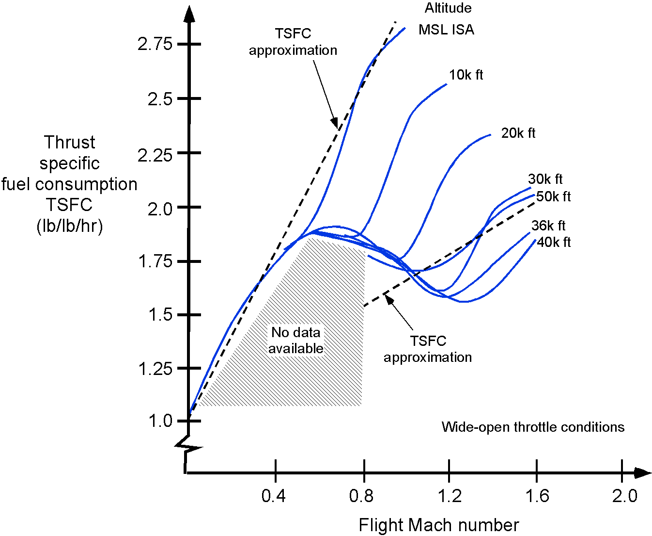
In performance analyses, one linear approximation that can be used for the TSFC in the subsonic regime is
(16) 
which is measured in units of fuel weight per unit of thrust per hour. The value of  is engine-specific and also depends on the engine’s throttle setting. However, a turbojet engine will run at or near wide-open throttle settings for most flight operations. Remember that air density is lower at higher flight altitudes, so the mass flow of air into the engine decreases.
In supersonic flight, the inlet to a turbojet engine must be designed so that the intake to the compressor occurs at subsonic speeds. This is done using a duct and/or doors or baffles in which the total pressure  increases according to the thermodynamic relationship
(17) ![\begin{equation*} \frac{p_{T}}{p_{\rm static}} = \left[ 1 + \frac{\gamma-1}{2} M_{\infty}^2 \right]^\frac{\gamma}{(\gamma - 1)} \end{equation*}](https://eaglepubs.erau.edu/app/uploads/quicklatex/quicklatex.com-e25e1b317e4d3939427183766b1d638a_l3.svg "Rendered by QuickLaTeX.com")
This duct provides total pressure recovery at the end of the inlet diffuser before the compressor stage. Therefore, thrust from a turbojet engine tends to increase linearly with the supersonic flight Mach number according to the approximate relationship
(18) 
These characteristics are obtained because as  increases and increases, and then increases and eventually becomes supersonic, which all combine to increase the thrust . Additionally, as illustrated in the figure above, the TSFC remains relatively constant or deteriorates slightly with
  in the supersonic regime; however, the overall propulsive efficiency still increases.
Check Your Understanding #2 – Using the TSFC in a calculation
Two turbojet engines power a military airplane. It has the following characteristics:
- In-flight mass = 37,991 kg.
- Engine inlet area, = 0.6 m
 .
. - Engine thrust specific fuel consumption (TSFC) = 231.84 kg/kN/hr
- Cruise speed, = 245.0 m/s.
- Pressure altitude = 34,000 ft, ISA standard conditions.
- Aircraft lift-to-drag ratio = 15.
Determine the thrust required from each engine, the mass flow rate through each engine, as well as the fuel mass flow rate and the jet velocity. All velocities are measured relative to the engine’s reference frame. Neglect all pressure difference effects.
Show solution/hide solution.
In level flight,  and
and  . Therefore, the net thrust required for flight will be
![\[ T = \frac{W}{L/D} = \frac{37,991 \times 9.81}{15} = 24.846~\mbox{kN} \]](https://eaglepubs.erau.edu/app/uploads/quicklatex/quicklatex.com-0fc12e01e3d76300edf65b92b5f9aabf_l3.svg "Rendered by QuickLaTeX.com")
so the thrust per engine,  , will be 12.423 kN.
At 34,000 ft ISA standard, the air density is 0.3953 kg/m. See here for a handy ISA calculator. Therefore, the mass flow rate into the engine is
![\[ \overbigdot{m}_i = \varrho_{\infty} \, A_i V_{\infty} = 0.3953 \times 0.6 \times 245.0 = 58.11~\mbox{kg/s} \]](https://eaglepubs.erau.edu/app/uploads/quicklatex/quicklatex.com-1447316b7377b7c5d8829d8f8da6edf2_l3.svg "Rendered by QuickLaTeX.com")
In this case, we are given the engine TSFC and the fuel flow rate,  , and must determine the mass flow rate exiting the engine. Note that the units of the TSFC are expressed in kilograms of fuel per kilonewton of thrust per hour. Converting to base units gives the TSFC as 231.84/10/3,600 = 6.44
 kg/N/s. Therefore, the fuel flow rate per engine is
![\[ \overbigdot{m}_f = \mbox{TSFC} \ T_e = 6.44 \times 10^{-5}\times 12.423 \times 10^3 = 0.8~\mbox{kg/s} \]](https://eaglepubs.erau.edu/app/uploads/quicklatex/quicklatex.com-b426fe8ed7c13512b4e10a9d7d0110cc_l3.svg "Rendered by QuickLaTeX.com")
Therefore, the mass flow exiting the engine is
![\[ \overbigdot{m}_e = \overbigdot{m}_i + \overbigdot{m}_f = 58.11 + 0.8 = 58.91~\mbox{kg/s} \]](https://eaglepubs.erau.edu/app/uploads/quicklatex/quicklatex.com-0d76088dff19c453ad3c53380aca84ba_l3.svg "Rendered by QuickLaTeX.com")
The thrust per engine, , is given by the momentum equation, i.e.,
![\[ T_e = \left( \overbigdot{m}_i + \overbigdot{m}_f \right) V_e - \overbigdot{m}_{\rm air} V_{\infty} + \left( p_e A_ e - p_{\infty} A_i \right) \]](https://eaglepubs.erau.edu/app/uploads/quicklatex/quicklatex.com-a6051879198f2eaaf38fdb02b3141ed4_l3.svg "Rendered by QuickLaTeX.com")
and with no pressure effects, it becomes
![\[ T_e = \overbigdot{m}_e V_e - \overbigdot{m}_i V_{\infty} = \left( \overbigdot{m}_i +\overbigdot{m}_f \right) V_e - \overbigdot{m}_i V_{\infty} = 12.423~\mbox{kN} \]](https://eaglepubs.erau.edu/app/uploads/quicklatex/quicklatex.com-a4937fbfa8bfc062ddaba8983702032e_l3.svg "Rendered by QuickLaTeX.com")
To solve for the exit velocity, , the previous equation can be rearranged to give
![\[ V_e = \frac{T_e + \overbigdot{m}_i V_{\infty}}{ \overbigdot{m}_i +\overbigdot{m}_f} \]](https://eaglepubs.erau.edu/app/uploads/quicklatex/quicklatex.com-600f700f190a5998a2fac6e25ed239dd_l3.svg "Rendered by QuickLaTeX.com")
Inserting the numerical values gives
![\[ V_e = \frac{ 12.423 \times 10^3 + 58.11 \times 245.0}{58.91} = 452.55~\mbox{m/s} \]](https://eaglepubs.erau.edu/app/uploads/quicklatex/quicklatex.com-a0808eba044b6ae2e8cc912099d6cf5c_l3.svg "Rendered by QuickLaTeX.com")
Afterburning
Military aircraft often require a significant increase in engine thrust for a relatively short time, such as during takeoff, climb, acceleration into supersonic flight, or some combat maneuvers. This thrust is achieved using an afterburner, as shown schematically in the figure below. An afterburner injects additional fuel into the engine exhaust and burns in an extended tailpipe. Afterburning is sometimes called reheat.
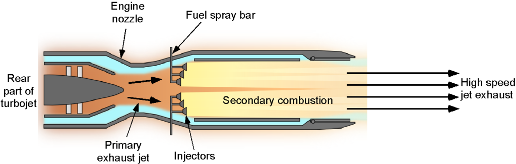
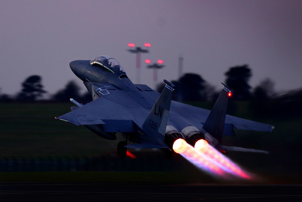
The afterburner tube contains fuel spray bars, flame holders, and an adjustable nozzle. An adjustable exhaust nozzle is necessary for an afterburning engine; two or three-position nozzles are usually used. Raw fuel is injected into the exhaust from the engine core by the fuel spray bars, and the flame holders stabilize the resulting combustion process as it develops down the tube and into the tailpipe. The engine’s core exhaust contains sufficient excess oxygen to enable afterburner operation, eliminating the need for additional inlets. The resulting exhaust flame from an afterburner is usually rather spectacular, partly because the flow speeds are supersonic, and the hot gases contain diamond-shaped shock waves, as shown in the photograph below.
In thermodynamic terms, an afterburner can be represented as a Brayton cycle with an additional isobaric heat addition process between the turbine exit and the nozzle. The turbine still provides the work to drive the compressor, but the afterburner raises the exhaust stream’s total temperature before it expands in the tailpipe. If  is the turbine exit temperature, then afterburning increases the stagnation temperature to
  , i.e.,
(19) 
where the  boost depends on the amount of fuel injected and burned. The effect on the diagram shown above is an additional horizontal step (constant pressure heat addition) between the turbine exit and the nozzle inlet. On the corresponding diagram, the cycle does not change shape significantly; however, the expansion through the nozzle begins from a higher total temperature, resulting in a higher jet velocity and, consequently, greater thrust.
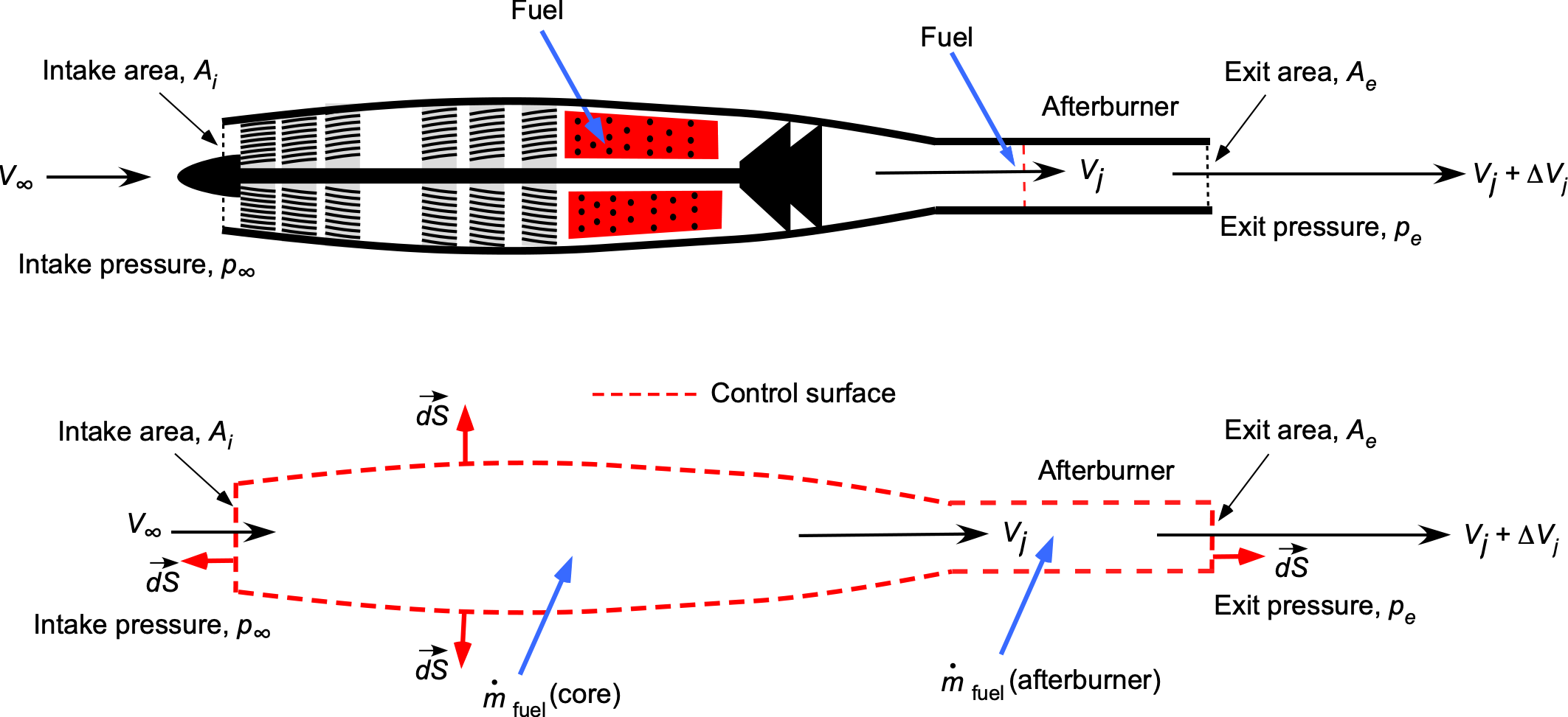
The thrust produced by a turbojet engine with an afterburner can be examined using conservation principles of fluid dynamics applied to a control volume surrounding the engine, as shown in the figure below. The secondary combustion in the afterburner significantly increases the exhaust velocity from to  , which raises the net thrust from to
  , as described by the momentum thrust relation
(20) 
where  denotes the mass flow rate and is the freestream velocity. If the increase in fuel mass flow rate is neglected compared to the air mass flow rate, so that
  , the thrust equation simplifies to
(21) 
This shows that the additional thrust produced by the afterburner is approximately equal to  , representing the extra momentum gained from the increase in jet exhaust velocity.
While the engine thrust may increase nearly twice when the afterburner is lit, the net engine TSFC increases markedly and proportionally more than the thrust, resulting in a corresponding increase in fuel burn. For example, published values for the Pratt & Whitney F100-PW-220, as used on the F-15 and F-16, are 0.76 lb lbhr without the afterburner and 1.94 lb lbhr with the afterburner. Because of the higher jet velocities out of the tailpipe, engine noise increases dramatically, i.e., according to Eq. 1. Afterburning is usually used by military fighter aircraft for takeoff and initial climb. In this case, the high noise levels produced using an afterburner are particularly noticeable to an observer on the ground. Concorde used afterburning turbojet engines.
Afterburning is also possible with a turbofan engine. Afterburning turbofans are typically found on military aircraft designed to achieve transonic and low-supersonic cruise speeds. When performance requirements span these speed ranges and subsonic flight under various conditions, selecting a low-bypass-ratio turbofan engine is usually the best design compromise to meet the flight requirements. In all cases, however, matching an engine to an aircraft requires careful consideration of not only the aircraft’s requirements but also weight, cost, and installation issues.
Check Your Understanding #3 – Performance of a turbojet engine with an afterburner
Consider a turbojet with an afterburner on an airplane flying at an altitude of 35,000 ft with a true airspeed = 530 mph; refer to the figure below. The inlet area is 13 ft . At this altitude,
  = 0.2353, and
  = 0.3099. The fuel-to-air ratio by mass injected into the engine core is 0.005, and the fuel-to-air ratio by mass injected into the afterburner is 0.016. The jet velocity is 1,510 ft s without afterburner, and
  2,700 ft s with the afterburner ignited. The flow is fully expanded, so there is no pressure difference. Assume a one-dimensional, steady flow.
- Calculate the thrust produced at this flight condition without the afterburner.
- Determine the equivalent propulsive power produced without the afterburner.
- Calculate the fuel consumption (in units of lb hr) and the thrust-specific fuel consumption (TSFC) without the afterburner.
- Determine the propulsive efficiency without the afterburner.
- If the afterburner is ignited, what is the new thrust produced?
- What is the new TSFC with the afterburner? Comment on your result compared to that without the afterburner.
Show solution/hide solution.
- The thrust is found from the momentum equation for steady one-dimensional flow, neglecting pressure differences, which gives
![\[ T = \overbigdot{m}_{\text{air}} (V_j - V_{\infty}) + \overbigdot{m}_{\text{fuel}} V_j \]](https://eaglepubs.erau.edu/app/uploads/quicklatex/quicklatex.com-430a9694716bfcc6b41af91d848b8c77_l3.svg "Rendered by QuickLaTeX.com")
The mass flow rate of air is
![\[ \overbigdot{m}_{\text{air}} = \varrho_{\infty} V_{\infty} A_{\infty} \]](https://eaglepubs.erau.edu/app/uploads/quicklatex/quicklatex.com-f062915a681302aca554a74cb9c4ea26_l3.svg "Rendered by QuickLaTeX.com")
Convert
to ft/s to get![\[ V_{\infty} = 530 \times \frac{5,280}{3,600} = 777.0~\text{ft/s} \]](https://eaglepubs.erau.edu/app/uploads/quicklatex/quicklatex.com-a8c94a6b085a431f0b07916a04a6a3be_l3.svg "Rendered by QuickLaTeX.com")
The standard sea-level density is
 = 0.002377 slug/ft
 , so
, so![\[ \varrho_{\infty} = 0.3099 \times 0.002377 = 0.000736~\text{slug/ft}^3 \]](https://eaglepubs.erau.edu/app/uploads/quicklatex/quicklatex.com-934e98007dc4a4b8ccd45c4eff85751a_l3.svg "Rendered by QuickLaTeX.com")
Therefore,
![\[ \overbigdot{m}_{\text{air}} = 0.000736 \times 777 \times 13 = 7.41~\text{slug/s} \]](https://eaglepubs.erau.edu/app/uploads/quicklatex/quicklatex.com-73a5ef2d028f50b44a49f04ae838df7d_l3.svg "Rendered by QuickLaTeX.com")
The core fuel-to-air ratio is
 , so
, so![\[ \overbigdot{m}_{\text{fuel}} = f \, \overbigdot{m}_{\text{air}} = 0.005 \times 7.41 = 0.03705~\text{slug/s} \]](https://eaglepubs.erau.edu/app/uploads/quicklatex/quicklatex.com-64d797c998f9201a5df7e1949f1f882a_l3.svg "Rendered by QuickLaTeX.com")
Therefore, the thrust is
![\[ T = 7.41 (1,510 - 777) + 0.03705 \times 1,510 = 5,486~\text{lb} \]](https://eaglepubs.erau.edu/app/uploads/quicklatex/quicklatex.com-430e047de6410d409fed46470972ba68_l3.svg "Rendered by QuickLaTeX.com")
- The equivalent propulsive power is
![\[\]](https://eaglepubs.erau.edu/app/uploads/quicklatex/quicklatex.com-b40a4d53f62082f3e685154172b5de44_l3.svg "Rendered by QuickLaTeX.com")
![\[ P_{\text{eq}} = T V_{\infty} = 5,486 \times 777 = 4,263,222~\text{ft-lb/s} \approx 7,751~\text{hp} \]](https://eaglepubs.erau.edu/app/uploads/quicklatex/quicklatex.com-f15296ab2a56ad9d0235d1f0e2a0812c_l3.svg "Rendered by QuickLaTeX.com")
- The fuel mass flow rate in lb/s is
![\[ \overbigdot{W}_{\text{fuel}} = 0.03705 \times 32.17 = 1.19~\text{lb/s} \]](https://eaglepubs.erau.edu/app/uploads/quicklatex/quicklatex.com-a27235fb745636cb0b67777fe41e057c_l3.svg "Rendered by QuickLaTeX.com")
Converting to lb/hr gives
![\[ \overbigdot{W}_{\text{fuel}} = 1.19 \times 3,600 = 4,290~\text{lb/hr} \]](https://eaglepubs.erau.edu/app/uploads/quicklatex/quicklatex.com-f5d71343f4b3f3f9d7bfb4ce8d37789e_l3.svg "Rendered by QuickLaTeX.com")
The thrust-specific fuel consumption (TSFC) is
![\[ \text{TSFC} = \frac{\overbigdot{W}_{\text{fuel}}}{T} \]](https://eaglepubs.erau.edu/app/uploads/quicklatex/quicklatex.com-d9aefc4c96f94b95402a903cfba7ad15_l3.svg "Rendered by QuickLaTeX.com")
so that
![\[ \text{TSFC} = \frac{4,290}{5,486} = 0.782~\text{lb/hr/lb} \]](https://eaglepubs.erau.edu/app/uploads/quicklatex/quicklatex.com-f0141a7978dcbd089a34f46728706d51_l3.svg "Rendered by QuickLaTeX.com")
- The propulsive efficiency is
![\[ \eta_p = \frac{2V_{\infty}}{V_j + V_{\infty}} = \frac{2 \times 777}{1,510 + 777.0} = 0.68 \]](https://eaglepubs.erau.edu/app/uploads/quicklatex/quicklatex.com-bcd50a62ce8629c20e8b71c1b9153263_l3.svg "Rendered by QuickLaTeX.com")
- With the afterburner, the exit velocity is
 , and the afterburner adds additional fuel mass, i.e.,
![\[ f_{\text{total}} = 0.005 + 0.016 = 0.021 \]](https://eaglepubs.erau.edu/app/uploads/quicklatex/quicklatex.com-77e76337006366b041d7107e0c3400bd_l3.svg "Rendered by QuickLaTeX.com")
so that
![\[ \overbigdot{m}_{\text{fuel total}} = 0.021 \times 7.41 = 0.1556~\text{slug/s} \]](https://eaglepubs.erau.edu/app/uploads/quicklatex/quicklatex.com-2276ee1825f4620c05d9def553831ef1_l3.svg "Rendered by QuickLaTeX.com")
The new thrust is
![\[ T_a = 7.41 (2,700 - 777) + 0.1556 \times 2,700 = 14,670~\text{lb} \]](https://eaglepubs.erau.edu/app/uploads/quicklatex/quicklatex.com-7d37981bf8e0080a683f90ebf552abbb_l3.svg "Rendered by QuickLaTeX.com")
- The fuel mass flow in lb/hr is
![\[ \overbigdot{m}_{\text{fuel total}} = 0.1556~\text{slug/s} \times 32.17 = 5.004~\text{lb/s}= 5.004 \times 3,600 = 18,015~\text{lb/hr} \]](https://eaglepubs.erau.edu/app/uploads/quicklatex/quicklatex.com-4e201f40cdb758ef3cf8331801fd62f4_l3.svg "Rendered by QuickLaTeX.com")
so that
![\[ \text{TSFC}_{\text{afterburner}} = \frac{18,015}{14,670} = 1.228~\text{lb/hr/lb} \]](https://eaglepubs.erau.edu/app/uploads/quicklatex/quicklatex.com-f17c22b7fc4fc34bfbf30a73df9b22cb_l3.svg "Rendered by QuickLaTeX.com")
The TSFC with the afterburner is significantly higher than without the afterburner, indicating that afterburners greatly increase fuel consumption for a given amount of thrust.
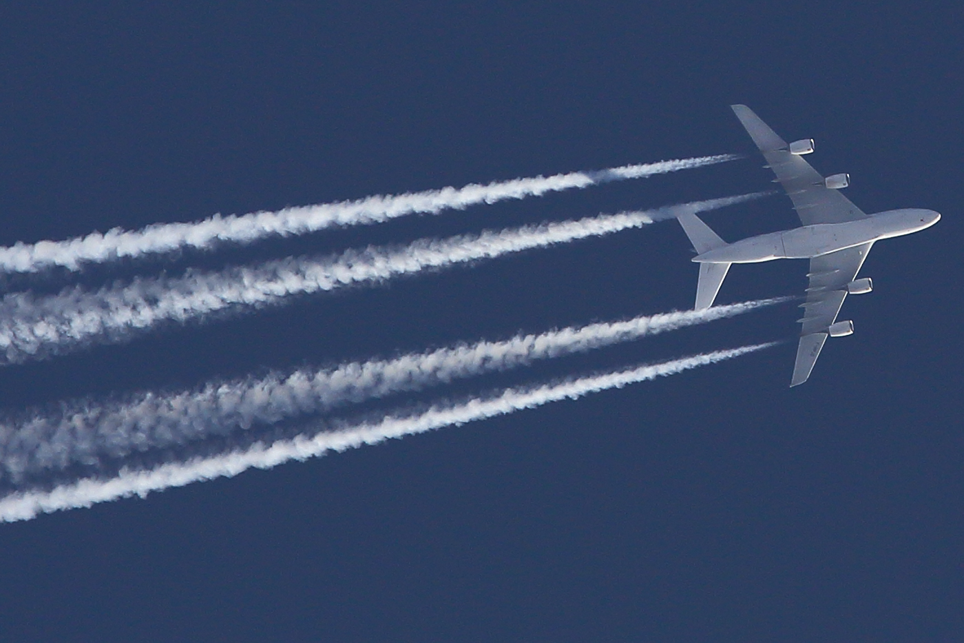
Why Jet Engines Form Contrails
Look up in the sky! What are those long white streaks trailing behind a high-flying airplane? These visible lines are called contrails, short for condensation trails. They form when the hot, moist exhaust from a jet engine mixes with the extremely cold air of the upper troposphere. As the mixture cools, it can no longer retain all its water vapor, so the excess condenses and freezes almost instantly, forming a thin line of ice crystals. A good illustration of this process is shown in the photograph below.
The amount of water vapor produced by a jet engine is directly proportional to its fuel mass-flow rate, i.e.,
(22) 
where  is the water emission index as a ratio of the mass for water vapor to the mass of fuel (in
  ) and
) and  is the fuel flow rate. Because the engine ingests far more air than fuel, it is convenient to define the air–fuel mass ratio as
  . With this, the exhaust water-vapor mixing ratio can be approximated by
(23) 
This quantity describes the humidity level in the exhaust immediately as it leaves the jet nozzle. After leaving the engine, the exhaust mixes turbulently with the surrounding air. The temperature and humidity of the mixture lie between the exhaust state  and the ambient state
  . If
. If  is the fraction of exhaust in the mixture, where
  is pure exhaust and
  is pure ambient air, then the mixture temperature and humidity are
(24) 
As the exhaust mixes and cools, which is often very rapidly because the ambient air may be colder than  , the mixture may reach a point where it cannot hold all of its water vapor. At that moment, condensation begins. To determine whether this happens, the actual water mixing ratio
  can be compared with the maximum amount of vapor the mixture can hold at its temperature, denoted
  . This leads to the saturation ratio given by
(25) 
A contrail will form if at any stage of mixing if  . This condition simply states that the mixture has become saturated and “full” of water vapor. Any excess condenses into droplets, which then freeze almost immediately into ice crystals. If this saturation condition is not reached, no contrail will appear even though water vapor is present in the exhaust.
Whether a contrail persists after forming depends on the ambient air’s relative humidity with respect to ice. If  is the ambient vapor pressure and
  is the saturation vapor pressure over ice at the ambient temperature, then the relative humidity can be expressed as
(26) 
which is the relative humidity with respect to ice. Ice crystals remain stable or grow when  , leading to a persistent contrail that may spread under upper-level winds. When
  , the ice crystals sublimate, and the contrail dissipates quickly.
In practical terms, the engine type and its characteristics determine how much water enters the exhaust and its initial temperature, but the surrounding atmosphere controls nearly everything else: whether the mixture becomes saturated, whether ice crystals form, and whether the contrail lasts for seconds or for many minutes. This is why two aircraft flying at nearly the same flight level can produce very different contrail signatures when they pass through slightly different layers of temperature or humidity.
Ramjets
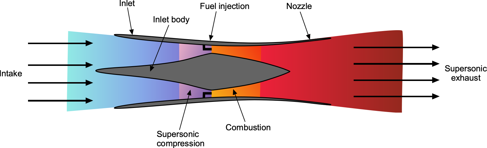
Finally, a description of a ramjet engine is appropriate in that engine category. A ramjet is a straightforward air-breathing jet engine with no rotating or moving parts, much like an afterburner. Ramjets employ a continuous combustion process, in which fuel is injected and burned in a circular flame holder, as shown in the schematic below. A ramjet cannot produce thrust when it is stationary; therefore, it must be accelerated to a high airspeed, at which point it begins to produce thrust. Ramjets are most effective at supersonic conditions, specifically above Mach 3. Ramjets have been used in supersonic missiles and other weapon systems. However, the Fairey Rotodyne gyroplane utilized ramjets to power its rotor, employing a reaction-drive rotor system.
Ramjets, despite their simplicity, have various limitations. One is that they cannot produce thrust at zero airspeeds; they must be accelerated to some minimum airspeed by another means. Second, they are very inefficient at low flight Mach numbers. Consequently, the TSFC of a ramjet is very poor at low Mach numbers and may be nearly an order of magnitude worse than that of a turbojet. Furthermore, as the Mach number increases, the efficiency of a ramjet improves markedly and may exceed that of a turbojet, but then decreases again as a result of compression-induced reductions in inlet temperature. However, its TSFC is reasonably good at supersonic Mach numbers above 3.0. Therefore, it is an attractive propulsion system for a hypersonic aircraft, known as a scramjet (supersonic ramjet).
To understand ramjet performance, consider an idealized model based on steady, one-dimensional, isentropic flow, neglecting friction and shock losses except across the combustor where heat is added. The total temperature at the inlet is given by
(27) 
where  is the total (stagnation) temperature at the inlet,
  is the freestream static temperature,
  is the freestream Mach number, and
  is the ratio of specific heats, usually 1.4 for air. Fuel is burned at constant pressure, raising the total temperature to
  . The resulting hot gas is then expanded through the nozzle. Assuming full expansion to ambient pressure, the exhaust velocity is given by
(28) 
where  is the specific heat at constant pressure. The net thrust per unit mass flow is then
(29) 
where  is the freestream velocity and is the incoming air mass flow rate. Recall that the thrust-specific fuel consumption is defined as
(30) 
where  is the fuel-to-air mass ratio. The small difference between
  and
and  at low Mach numbers leads to low thrust and high TSFC. The increased inlet stagnation temperature and greater heat-addition capability improve thrust and reduce TSFC at moderate supersonic Mach numbers. At high Mach numbers, the growing inlet temperature limits further increases in , reducing the thermal efficiency and causing TSFC to rise again. This behavior defines the useful performance envelope of the ramjet engine.
Fuels for Turbojet Engines
Turbojet and other gas turbine engines require fuels that are chemically stable, energy-dense, and capable of reliable performance under extreme operating conditions, including high altitudes and wide temperature variations. Jet fuels are refined to meet these criteria, emphasizing combustion properties, thermal stability, and safety characteristics such as flash point.
The most widely used jet fuels in aviation are categorized into standard types. The two principal grades are Jet A and Jet A-1. Jet A is primarily used in the United States, while Jet A-1 is the international standard. Both fuels are kerosene-based, with Jet A-1 having a slightly lower freezing point of  compared to Jet A’s
  , enhancing its suitability for long-haul international flights at high altitudes. These fuels have a high energy content of approximately 43 MJ/kg and a density of approximately 0.80 kg/L at standard conditions.
Jet fuels must have a sufficiently high flash point to minimize fire hazards. Jet A and Jet A-1 have minimum flash points of approximately  , ensuring that the fuels do not vaporize excessively at ground temperatures. In addition to flash point, freezing point is critical, as turbine aircraft routinely operate at stratospheric altitudes where ambient air temperatures can fall below
  .
.
Another important aviation fuel is JP-8, a military-grade kerosene similar to Jet A-1 but containing additional additives to enhance thermal stability, reduce the risk of icing, and improve lubrication. Historically, JP-4, a wide-cut fuel blending gasoline and kerosene fractions, was used extensively in military aviation. Still, it has largely been replaced because of its lower flash point and greater volatility, which pose increased fire risks. Jet B, a wide-cut fuel that contains a higher proportion of lighter hydrocarbons, is limited in frigid climates because of its good low-temperature properties. However, its higher volatility and handling risks have limited its adoption in civil aviation.
The combustion of jet fuel in a turbojet engine releases thermal energy that drives the turbine and produces high-velocity exhaust, which generates thrust. The basic energy balance can be expressed by the relationship
![\[ \overbigdot{Q}_{\text{in}} = \overbigdot{m}_{\text{fuel}} \, h_{\text{comb}} \]](https://eaglepubs.erau.edu/app/uploads/quicklatex/quicklatex.com-07b9e3bc2052647c89de1434379f2967_l3.svg "Rendered by QuickLaTeX.com")
where  is the mass flow rate of the fuel and
  is the lower heating value of the fuel, typically around 43 MJ/kg for kerosene-based fuels.
Because turbojets operate continuously at high temperatures and pressures, fuel properties such as thermal oxidative stability are also critical. Fuel degradation under heat, known as coking, can lead to deposits in fuel nozzles and afterburners, reducing engine performance and reliability. The proper selection, certification, and management of jet fuels are essential to ensure the safe and efficient operation of turbine-powered aircraft. Understanding the physical and chemical characteristics of these fuels forms a fundamental part of aerospace engineering education.
Summary & Closure
The turbojet engine is a classic solution to jet propulsion and is ideally suited for high subsonic or supersonic flight. Today, turbojets are used more on military aircraft. For supersonic flight, the turbojet will be fitted with an afterburner, which can provide twice the thrust. However, this capability can only be used for short periods because of the resulting high fuel consumption. For the most part, choosing a turbojet for an aircraft that cruises below Mach 0.5 is inappropriate; a turboprop should be used instead, as it has significantly better specific fuel consumption. Using a turbofan at higher airspeeds is more efficient than a turbojet because it has a lower specific fuel consumption. A turbofan also produces much lower noise as a consequence of its lower jet velocity. With increasingly stringent aircraft engine noise constraints, the pure turbojet may eventually be relegated to aeronautical history, even for military aircraft.
5-Question Self-Assessment Quickquiz
For Further Thought or Discussion
- Explain why increasing the flight Mach number improves a turbojet’s overall propulsive efficiency.
- Study the SR-71 and Concorde supersonic aircraft. What kinds of engines did they use? Did they use afterburning (reheat)?
- How does the afterburner affect the performance of a turbojet engine, and under what conditions is it typically used?
- Explain the concept of thrust-to-weight ratio and its significance in determining the performance characteristics of a turbojet engine.
- What are the primary factors that influence the efficiency of a turbojet engine, and how can these factors be optimized?
- Discuss the typical applications of turbojet engines and provide examples of aircraft that utilize this type of propulsion system.
- Describe any recent advancements or technological developments in turbojet engine design that have improved performance or fuel efficiency.
Other Useful Online Resources
- A great video on how jet engines work.
- A video on World War 2 Jet Power.
- How Jet Engines Transformed Our World: A History Channel video.
- An excellent early film on the history of the gas turbine engine.
- To learn more about afterburning and turbojets, check out these articles from science.gov.
- You can learn more about turbojets from the NASA website.
- A good video shows the internals of a turbojet engine as well as its running.
- A fun video on a turbojet-powered scooter!
- Video explaining the detailed design and inner workings of a jet engine.
