45 Turbofan & Turboprop Engines
Introduction
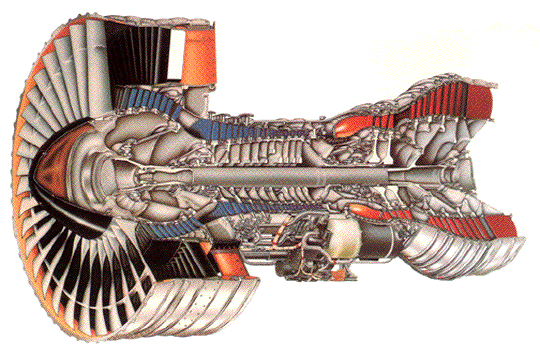
The turbofan and the turboprop are two variations of the primary gas turbine engine, sharing certain design similarities. They are both variations of the primary turbine engine, so their thermodynamics are based on the Brayton cycle. Similarly sized engines deliver power similar to that of the fan or propeller. The turbofan features a large fan stage at the front of the engine core, as illustrated in the cutaway below. The turbofan is a highly efficient way to produce thrust, particularly when it uses a high bypass ratio, in which most of the mass flow passes through the fan, which generates the majority of the thrust. Turbofans have been used to power commercial airliners, such as the Boeing 747 and 767, and the Airbus A300 and A330, as well as many other aircraft. The turboprop utilizes a propeller driven by a power turbine, equivalent to a propulsion system with a very high bypass ratio.
The performance and analysis of turbofans and turboprops share many similarities. However, the propeller’s propulsive characteristics and aerodynamic limitations affect the operation of a turboprop as a system. Turboprops and turbofans have much higher thrust-to-fuel efficiency than turbojets. Turbofans are commonly used on many commercial airliners, although turboprops are often employed on smaller commuter aircraft. Turboprops are also used on some general aviation aircraft and military training aircraft. A turboshaft, which has the same essential core as a turboprop, can power helicopters and other machinery, as well as aircraft.
Learning Objectives
- Understand the functionality and characteristics of a turbofan engine and how it differs from a turbojet engine.
- Appreciate the concept of bypass ratio for a turbofan and how it contributes to its overall propulsive efficiency.
- Understand the characteristics of turboprop and turboshaft engines.
Design Characteristics of a Turbofan
The flow in a turbofan engine is split into two paths, as shown in the figure below:
- The flow through the engine’s core is similar to that of a turbojet engine.
- The fan produces the surrounding axial “bypass” flow.
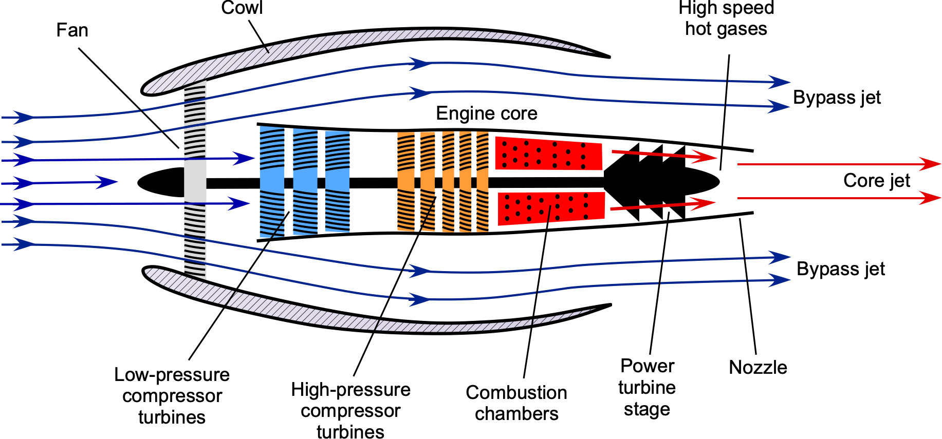
The fan spins much more slowly than the engine’s inner core, which contributes to its efficiency and reduces noise. A cowl surrounds the fan stage, guiding the airflow into the fan and the engine core. It is found that the thrust-producing efficiency of this type of engine increases significantly with increasing bypass ratio. Recall that the bypass ratio (BPR) is the area or mass flow through the fan divided by the area or mass flow through the core itself, i.e.,
(1) 
Like all engines, the thrust and fuel consumption of a turbofan vary with flight conditions, i.e., airspeed (Mach number) and flight altitude. Such characteristics are determined from engine performance measurements, supported by mathematical modeling. However, remember that altitude typically refers to the density altitude, i.e., the altitude corresponding to the local ambient air density.
Thrust Production
The thrust-producing capabilities of turbofan engines are found to be significantly affected by the airspeed  and the corresponding Mach number
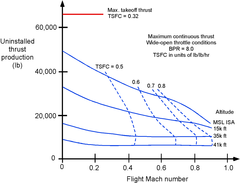
  , and their thrust production decreases at higher airspeeds. The typical takeoff and climbing phase behavior is shown below, which occurs at relatively low airspeeds, typically below about 300 kts (flight Mach numbers less than 0.5). Notice the reduction in thrust with increasing flight Mach number, a characteristic of this engine type. At higher Mach numbers, the thrust curves tend to flatten out at higher altitudes; however, at lower altitudes, thrust production diminishes quickly at transonic Mach numbers.
For design purposes, equations describing an engine’s characteristics are often helpful. During the takeoff and climb phase, the thrust for a turbofan engine is often approximated using the empirical equation
(2) 
The thrust from a turbofan can also be approximated using the equation
(3) 
where the values of the coefficients  and
and  depend not only on the engine type but also on its operational altitude. Notice that the variations of thrust with and are relatively large at lower altitudes. However, the assumption that thrust is almost constant is reasonable in the cruise range (say, between flight Mach numbers of 0.7 to 0.85 at higher flight altitudes). The same basic variation of thrust with altitude holds for turbofan engines, i.e.,
(4) 
where  is the thrust produced at MSL. Notice that
  in most cases, although the value may depend on the engine design.
Check Your Understanding #1 – Thrust and power from a turbofan
An aircraft flying at a true airspeed, of 200 m/s, is powered by a turbofan engine with a bypass ratio of 5:1. The mass flow rate into the engine core is 20 kg/s, and the fuel consumption is 2 kg/s. The average discharge flow velocity from the engine core,  , is 410 m/s, and from the bypass fan,
  , it is 270 m/s, both with respect to the engine. Using conservation principles, show an appropriate control volume and control surface to analyze this problem. Determine the thrust and equivalent power developed by this turbofan engine. Neglect all pressure difference effects.
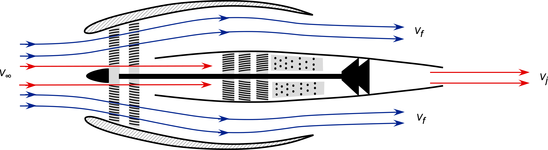
Show solution/hide solution.
The control volume analysis of this problem is shown below.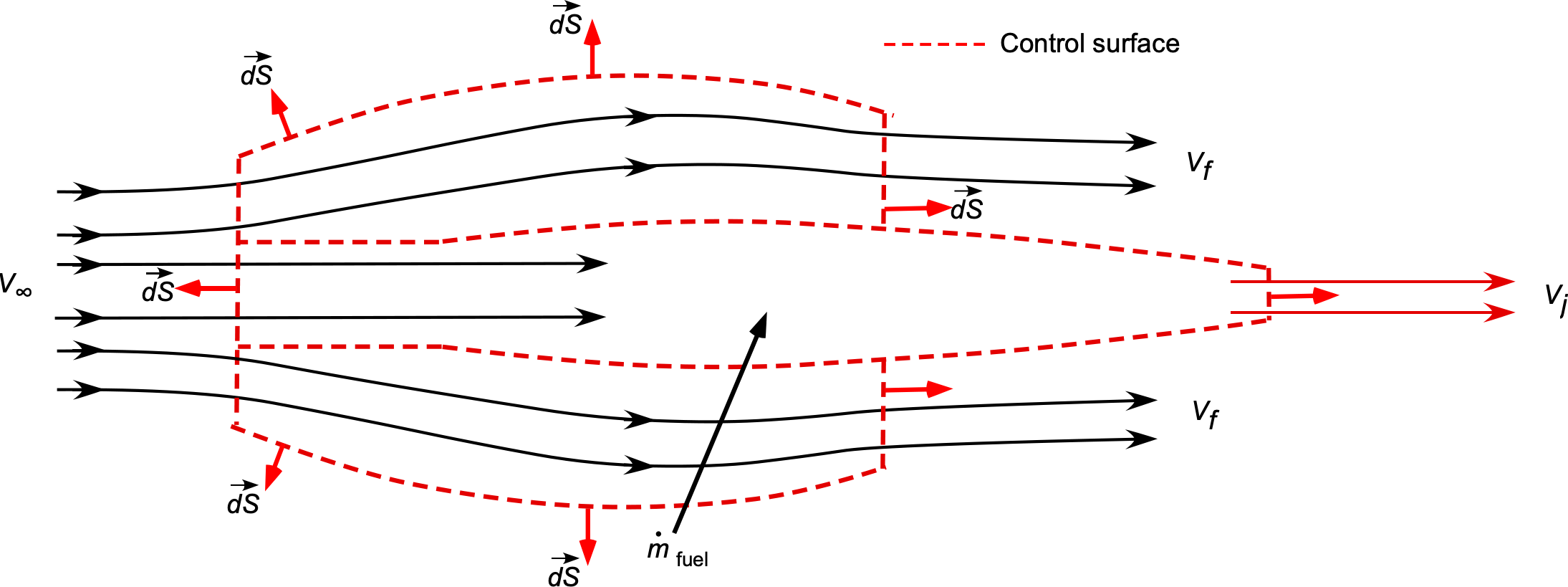 The mass flow of air into the core of the engine is
![\[ \overbigdot{m}_{\rm core} = 20~\mbox{kg/s} \]](https://eaglepubs.erau.edu/app/uploads/quicklatex/quicklatex.com-2645702eafef9228f28dac0908232744_l3.svg "Rendered by QuickLaTeX.com")
and with a bypass ratio of 5:1, the mass flow into the fan will be
![\[ \overbigdot{m}_{\rm fan} = 5 \overbigdot{m}_{\rm core} = 100~\mbox{kg/s} \]](https://eaglepubs.erau.edu/app/uploads/quicklatex/quicklatex.com-93f7dff8884e97e2b1c46162642b25d9_l3.svg "Rendered by QuickLaTeX.com")
The mass flow rate of fuel is
![\[ \overbigdot{m}_f = 2~\mbox{kg/s} \]](https://eaglepubs.erau.edu/app/uploads/quicklatex/quicklatex.com-e09a57219544c9070855abe4cae9fe35_l3.svg "Rendered by QuickLaTeX.com")
Therefore, the thrust from the engine core is
![\[ T_{\rm core} = (\overbigdot{m}_{\rm core} + \overbigdot{m}_f) V_{\rm core} - \overbigdot{m}_{\rm core} V_{\infty} \]](https://eaglepubs.erau.edu/app/uploads/quicklatex/quicklatex.com-0aa8977f9147e2154733022ef81f8c80_l3.svg "Rendered by QuickLaTeX.com")
From the fan, the thrust is
![\[ T_{\rm fan} = \overbigdot{m}_{\rm fan} V_{\rm fan} - \overbigdot{m}_{\rm fan} V_{\infty} = \overbigdot{m}_{\rm fan} \left( V_{\rm fan} - V_{\infty} \right) = 5 \overbigdot{m}_{\rm core} \left( V_{\rm fan} - V_{\infty} \right) \]](https://eaglepubs.erau.edu/app/uploads/quicklatex/quicklatex.com-5630e989f74fcaa0ae2e9b9a27c913fb_l3.svg "Rendered by QuickLaTeX.com")
The total thrust is then
![\[ T = T_{\rm core} + T_{\rm fan} \]](https://eaglepubs.erau.edu/app/uploads/quicklatex/quicklatex.com-2811fab30cea9573de16c680e5be3856_l3.svg "Rendered by QuickLaTeX.com")
In this case we are given that  = 20 kg/s,
  = 2 kg/s, and also that
  = 410 m/s,
  = 270 m/s, and = 200 m/s. Therefore, substituting the numbers gives
![\[ T_{\rm core} = (20.0 + 2.0 ) 410.0 - (20.0) 200 = 9,020 - 4,000 = 5.02~\mbox{kN} \]](https://eaglepubs.erau.edu/app/uploads/quicklatex/quicklatex.com-be4894523255c2adc063bb0b0a7f4e3b_l3.svg "Rendered by QuickLaTeX.com")
and
![\[ T_{\rm fan} = 5 (20.0) (270.0 - 200.0) = 7.0~\mbox{kN} \]](https://eaglepubs.erau.edu/app/uploads/quicklatex/quicklatex.com-d04806e62ec41736032958a5c1f8c214_l3.svg "Rendered by QuickLaTeX.com")
The total thrust is
![\[ T = T_{\rm core} + T_{\rm fan} = 5.02 + 7.0 = 12.02~\mbox{kN} \]](https://eaglepubs.erau.edu/app/uploads/quicklatex/quicklatex.com-69e302e900110d46d7d1f2cb9d7e0406_l3.svg "Rendered by QuickLaTeX.com")
The equivalent net power  that is developed is
![\[ P = T V_{\infty} = 12.02 \times 10^3 \times 200 = 2.4~\mbox{MW} \]](https://eaglepubs.erau.edu/app/uploads/quicklatex/quicklatex.com-121e221e5ad313105cb6a208d978e991_l3.svg "Rendered by QuickLaTeX.com")
Thermodynamics
Turbofan and turboprop engines are both practical realizations of the Brayton cycle, as previously discussed in detail in previous chapters of this eBook. All gas turbine engines embody the same fundamental Brayton-cycle processes: isentropic compression, constant-pressure heat addition, isentropic expansion, and constant-pressure heat rejection. However, they differ in how the turbines work and how the exhaust energy is divided between thrust and shaft power.
In a turbojet, nearly all of the turbine expansion work is used to drive the compressor, with only the residual gas enthalpy expanding through the nozzle to produce jet thrust. The cycle follows the ideal Brayton sequence: the compressor raises the total pressure and temperature from  to
to  , combustion adds heat at nearly constant pressure to reach
  , and the turbine expands the gas isentropically to
  while extracting just enough work to drive the compressor. The remaining total enthalpy drop
  to
to  in the nozzle converts to kinetic energy to generate thrust.
A turbofan modifies this balance by adding a ducted fan driven by an additional turbine stage. Part of the turbine work now drives the fan, which accelerates a larger mass flow at a lower exhaust velocity. This redistribution of the available turbine power increases propulsive efficiency at subsonic speeds. The core flow (compressor–combustor–turbine) still undergoes the same Brayton-cycle transformations, but the total temperature ratio across the fan  and the bypass ratio strongly influence the overall efficiency.
In a turboprop or turboshaft engine, the Brayton cycle again provides the thermodynamic foundation, but most of the turbine expansion is converted to mechanical shaft power rather than jet thrust. The turbine expands the flow through additional stages to extract nearly all remaining enthalpy, driving a reduction gearbox and propeller or rotor. Only a small fraction of the exhaust energy contributes to residual jet thrust. These engines therefore operate with low exhaust velocities but high overall propulsive efficiency at low to moderate flight speeds, reflecting an energy partition that favors shaft power over momentum thrust.
Propulsive Efficiency
The net propulsive efficiency of a turbofan engine can be defined as
(5) 
Therefore, for the engine core and the fan together, then
(6) 
It will be apparent that the higher the bypass ratio,  , all other factors being equal, the higher the net propulsive efficiency. Introducing the
  into the previous equation gives
(7) 
By substituting  into the previous equation gives
(8) 
and so
(9) 
This form of the equation for propulsive efficiency further underscores the importance of the bypass ratio. The term  shows that increasing the
  (all else being equal) increases the fraction of the fan contribution, which tends to be more efficient if
  is closer to , i.e., accelerating a large mass flow rate at a relatively low velocity.
Thrust Specific Fuel Consumption (TSFC)
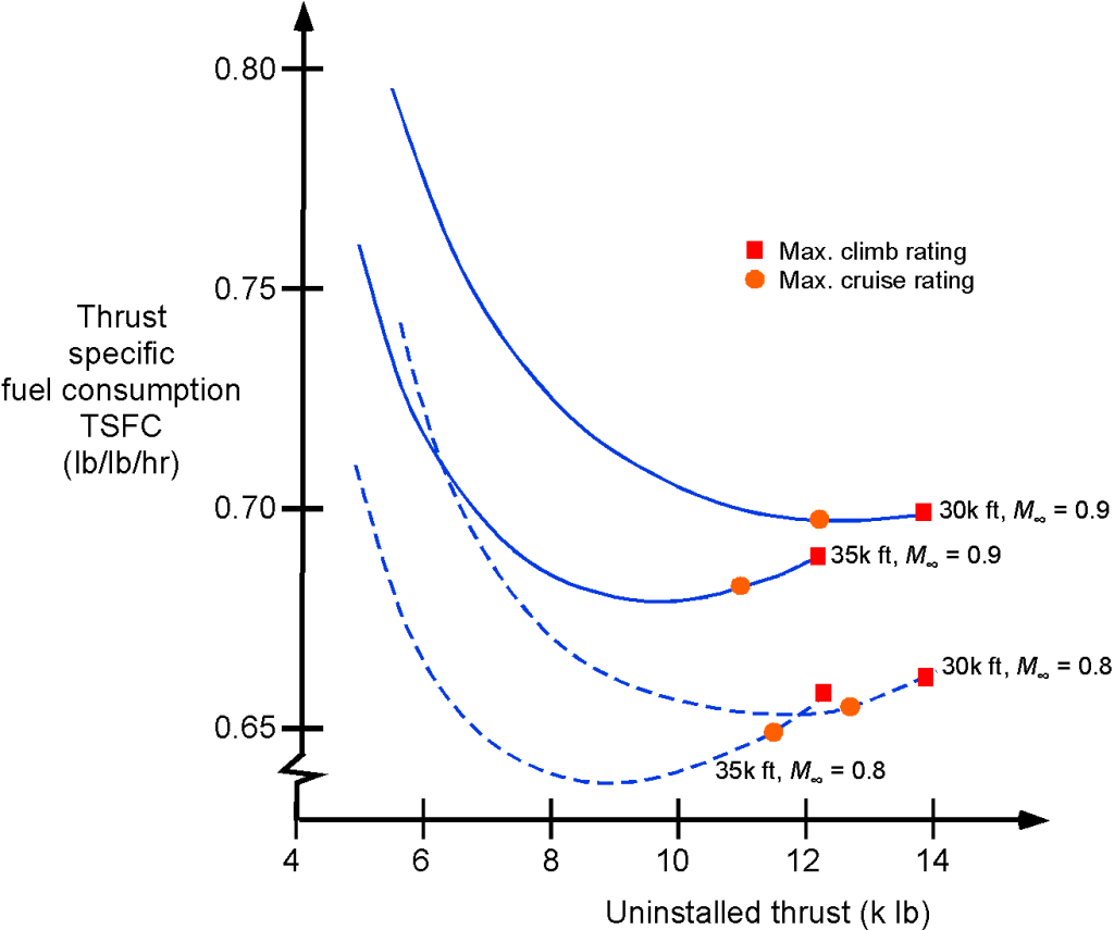
A representative thrust-specific fuel consumption (TSFC) map for a turbofan engine is shown in the figure below. For modeling purposes, the variation of the TSFC for a turbofan follows the relation
(10) 
where the values of  and
and  depend on the engine and its operational altitude. This latter equation has good validity in the cruise condition over a flight Mach number range of 0.7 to 0.85. The effect of altitude on the TSFC of a turbofan engine is fairly small (notice the greatly expanded scale), so the assumption that TSFC is constant is reasonable for use in a first-level aircraft flight performance analysis.
Afterburning Turbofans
Afterburning turbofans, such as the Pratt & Whitney F100 and the General Electric F110, are designed explicitly for supersonic-capable fighter airplanes, where a balance between subsonic fuel economy and transonic/supersonic thrust is crucial. These engines typically operate with a bypass ratio of 0.3 to 0.9, making them distinct from both high-bypass commercial engines and zero-bypass turbojets. In engines like the F100-PW-229, used on the F-15E and F-16C, the bypass ratio is approximately 0.36, while in the F110-GE-129, also used on the F-15 and F-16, the ratio is closer to 0.87. These bypass ratios are not selected for low noise or subsonic cruise performance, as in commercial turbofans, but rather to increase specific thrust (thrust per unit airflow), improve propulsive efficiency, and reduce fuel burn during loiter and subsonic cruise.
From a flowpath perspective, the afterburner is downstream of the turbine and acts only on the core exhaust stream. The bypass stream does not pass through the burner; instead, it enters the nozzle annulus and mixes with the core flow before or within the variable-area convergent-divergent nozzle. This mixing increases the mass flux through the nozzle and helps cool the afterburner liner. The net jet velocity in afterburning mode typically exceeds Mach 2.2 at the nozzle exit. The thrust of a low-bypass turbofan can be expressed as
(11) 
where only the core stream has the afterburner. This configuration offers a compromise between the high specific thrust of a turbojet and the improved propulsive efficiency of a turbofan, particularly in the subsonic regime.
The nozzle design is critical because the exhaust nozzle must accommodate a significant increase in total volume flow when the afterburner is lit because of the addition of fuel mass and thermal expansion. As a result, variable-area nozzles are required. These nozzles adjust the throat and exit areas in real time to maintain proper pressure matching and prevent choked flow or separation. On engines such as the F119 used in the F-22, the nozzle also incorporates two-dimensional thrust-vectoring, enabling pitch and yaw control at high angles of attack.
In dry mode (non-afterburning), these engines produce thrust levels on the order of 16,000–18,000 lb (71.2–80.1 kN), with a total specific fuel consumption (TSFC) of around 0.75 to 0.80 lb/lb/hr (76.5 to 81.6 kg/kN/hr). When the afterburner is engaged, thrust increases by 60% to 70%, with the F100-PW-229 reaching 29,000 lb (129.0 kN) of thrust at sea level static conditions. However, this comes at the cost of a TSFC that typically exceeds 1.9 lb/lb/hr (193.8 kg/kN/hr) and may reach over 2.1 lb/lb/hr (214.2 kg/kN/hr) at high altitudes and Mach numbers. The high fuel burn rate is acceptable for tactical scenarios that require short-duration bursts of power, such as intercepts, combat maneuvering, or takeoffs from short runways.
Design Characteristics of a Turboprop
A turboprop is a turboshaft engine at its core, as shown in the figure below. However, a low-pressure power turbine drives a propeller via a shaft, and only a small amount of jet thrust is produced; i.e., by design, is relatively low, which also helps keep noise lower. In fact, in this type of design, approximately 95% of the thrust comes from the propeller, while only 5% comes from any residual jet thrust generated by the exhaust nozzle. The most common application of turboprop engines is for smaller, commuter-class aircraft. The turboprop engine is similar to the turboshaft, which is widely used to power helicopters. Examples of standard turboprop engines include the Pratt & Whitney PT6, used in many small commuter aircraft, and the Allison T56, which powers the Lockheed C-130 Hercules and the Lockheed P-3 Orion.
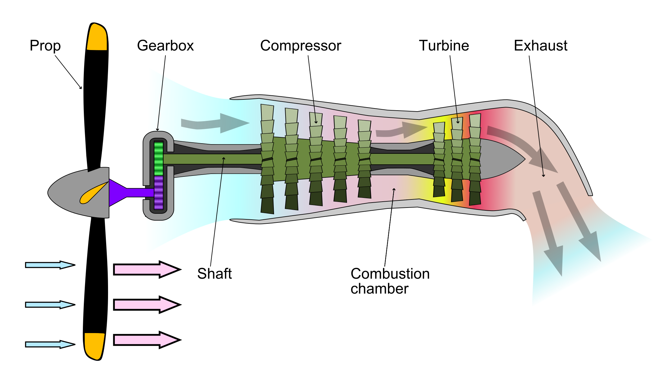
In the turboprop/shaft engine, the first three stages of the engine core are essentially the same for all gas turbine engines. However, in this case, the high-pressure turbine is followed by a low-pressure turbine, which powers the high-pressure compressor. The low-pressure power turbine, in turn, drives the propeller through a concentric shaft. The power turbine may be integral to the gas generator section, although most modern engines have a free power turbine on a separate concentric shaft that drives the propeller. This latter type of design enables the propeller to rotate freely, independently of the compressor’s rotational speed. Additionally, because of the increased expansion and energy extraction in the low-pressure power turbine stage, the exhaust jet’s residual energy is low, resulting in a small jet thrust at the exhaust nozzle, as previously discussed.
Propeller Contribution
The propeller may be coupled to the power turbine through a speed-reduction gearbox, which is necessary to keep the propeller tip speeds below the speed of sound. This approach maintains overall propulsive efficiency while reducing propeller noise. This gearbox is mounted on the front of the engine behind the propeller. However, the free-turbine design is more commonly used today, eliminating the penalties associated with weight and other issues related to the speed-reduction gearbox.
Because turboshaft engines power high-performance airplanes, the propeller is always a constant-speed (variable-pitch) type, similar to that used with higher-powered reciprocating engines. A constant-speed propeller allows the angle of the blades to adjust dynamically during operation. This ensures that the engine operates at its most efficient rotational speed, regardless of changes in power demand or airspeed. This propeller type is similar to those used in high-powered reciprocating engines. Still, it is optimized in terms of blade area and number of blades to handle the power output of a turbine engine, i.e., to deliver the power at the engine shaft as useful propulsive work.
Turboprop engines, which often power regional and utility aircraft, rely on this configuration to deliver high efficiency at lower speeds, making them ideal for short-haul flights. Adjusting the propeller blade pitch also enables reverse thrust during landing, improving braking performance and reducing wear on the aircraft’s wheel brakes.
Propulsive Efficiency
Regarding efficiency, the turboprop falls between the propeller and reciprocating engine combination and the turbofan or turbojet. Regarding airspeed capabilities, the maximum airspeed (or flight Mach number) of a turboprop-powered aircraft is limited by the propeller’s efficiency loss as blades operate at higher helical Mach numbers. This characteristic results from compressibility losses and the onset of shock waves at the propellers’ tips. For this reason, turboprops tend to be limited to lower airspeeds than turbojet- or turbofan-powered aircraft and to lower operational altitudes, where the speed of sound is higher.
The performance of the turboprop can be analyzed using the basic conservation principles. The total thrust from the turboprop is  , where
  is the propeller thrust and
  is the jet thrust, and so the power from the turboprop is
(12) 
Defining the shaft power as the power available from the engine, then
(13) 
where  is the propulsive efficiency of the propeller and
  is the power produced by jet thrust. Defining equivalent shaft power
  as an overall power that includes jet thrust gives
(14) 
or
(15) 
Thrust Specific Fuel Consumption (TSFC)
The TSFC for the turboprop will be
(16) 
which is measured in terms of weight per hour per unit thrust, e.g., in units of lb hr lb or kg kN hr. Again, remember the anomaly of the SI system where mass (kg) is often used for TSFC instead of weight (N), and this difference should be accounted for in calculations as needed. However, other definitions for TSFC for a turboprop can also be based on the net available power
  , the shaft power
  , or the “equivalent” shaft power , i.e.,
(17) 
The equivalent shaft power includes the small contribution from the jet thrust.
Both power and TSFC will vary with airspeed and altitude. For a turboprop, is approximately constant with up to a typical operational value of 0.6 or 0.65. The variation of with altitude follows the relationship
(18) 
where  is typical, although the exact value depends on the specifics of the engine design. The specific fuel consumption of a turboprop is found to be relatively constant with both airspeed and altitude.
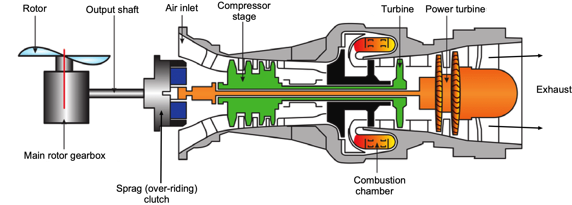
Turboshaft Engines
Turboshaft engines are very similar to turboprops in that they are designed to deliver power to a shaft, with only minor differences in their detailed design. Many engine manufacturers use a basic engine core, customized for either a turboprop or a turboshaft application. The differences among the engines are typically confined to the compressor stages, which are optimized to achieve the best pressure ratios for different operational flight scenarios, resulting in the highest power output and the lowest specific fuel consumption.
Turboshaft engines are commonly used in helicopters, which drive the rotor(s) through a gearbox and transmission system, as shown in the figure below. The advantage of a turboshaft engine for a helicopter is that it is both powerful and lightweight, offering a significantly better power-to-weight ratio compared to a piston engine. Turboshaft engines are used exclusively on helicopters, except for smaller general aviation (GA) helicopters, where piston engines are often a more cost-effective alternative. Turboshaft engines are also used as auxiliary power units to drive an electrical generator on larger airplanes. On ships, turboshafts are used for propulsion and can also be found on various other ground-based equipment.
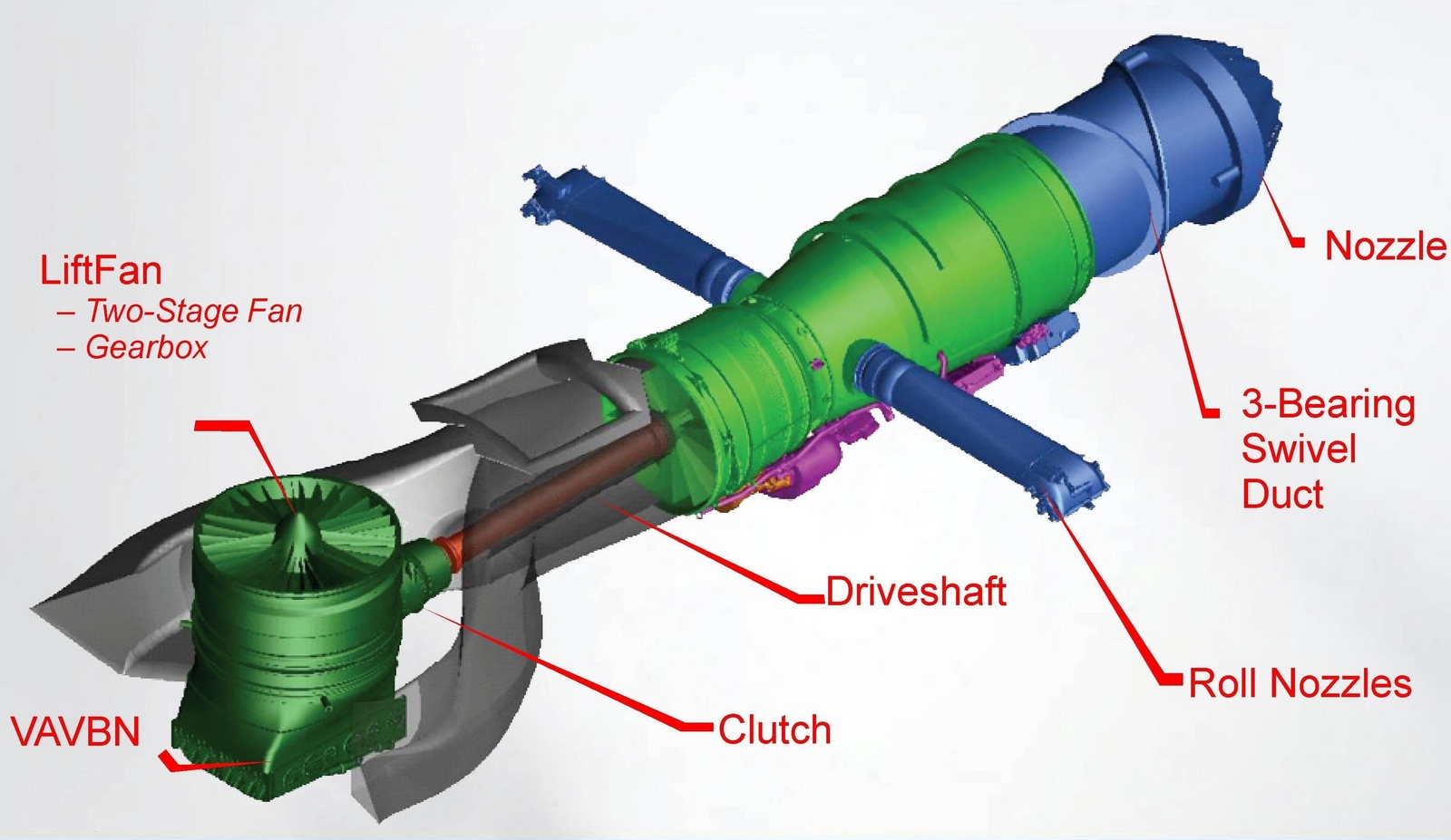
A unique application of the turboshaft engine is the 29,000 hp (21,300 kW) Pratt & Whitney F135-PW-600 afterburning turbofan engine for the STOVL version of the F-35B, as illustrated in the figure below. In conventional (airplane) mode, the engine operates as a turbofan. However, when powering the lift fan for VTOL operation, it operates in turboshaft mode, sending power through a shaft (i.e., similar to a turboprop). At the same time, the engine simultaneously continues to produce propulsive thrust as a turbofan.
Open Rotor Design
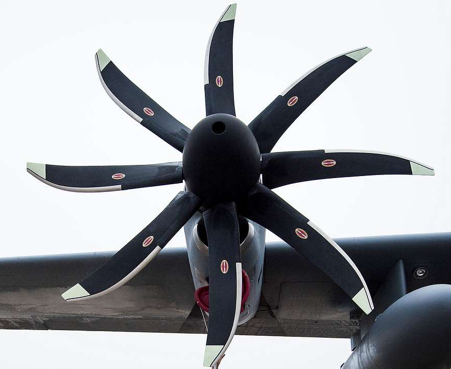
Open rotor engines, also known as unducted fans, represent a propulsion concept that seeks to deliver significantly higher propulsive efficiency than conventional turbofans by eliminating the nacelle and increasing the bypass ratio beyond what is practical in ducted configurations. As shown in the figure below, this type of engine uses one or more large-diameter, unshrouded fans, typically arranged in a single or contra-rotating pair, to accelerate a large mass of air at low velocity. By doing so, the open rotor minimizes the kinetic energy lost in the exhaust stream, thereby increasing propulsive efficiency in accordance with the ideal relation  , where is the jet velocity and is the flight speed. Because can be made only slightly greater than , especially in cruise, propulsive efficiencies well above 0.80 are theoretically attainable.
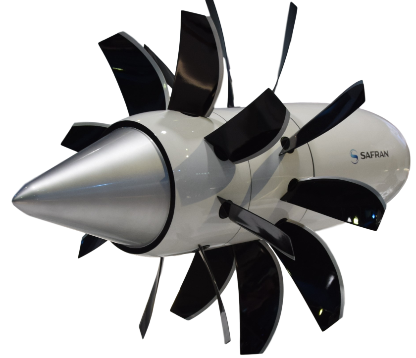
In most implementations, the open rotor employs two contra-rotating high-bypass fans mounted on a common axis and driven by a low-pressure turbine. The second stage recovers swirl energy from the first, improving axial thrust and reducing net torque. The configuration not only achieves higher bypass ratios, often exceeding 30:1, but also delivers a high thrust-to-weight ratio and fuel burn reductions on the order of 20% to 30% compared to existing turbofans. Cruise thrust-specific fuel consumption is expected to fall in the range of 0.45 to 0.55 lb/lb/hr (45.9 to 56.1 kg/kN/hr), making the open rotor attractive for future medium- to long-range transport aircraft operating at Mach 0.75 to 0.78 and altitudes of 35,000 to 38,000 ft.
Despite its aerodynamic advantages, the open rotor faces significant challenges related to aeroacoustics and integration. The absence of a duct exposes the rotor blades directly to the freestream, resulting in high tonal noise from periodic blade-passage interactions and broadband noise from turbulent wake-blade interactions. These effects are exacerbated in contra-rotating configurations, where the trailing rotor operates in the unsteady wake of the leading stage. Tip vortex–shock interactions at high blade-tip Mach numbers further contribute to acoustic emissions. As a result, open rotors produce significantly more noise than ducted turbofans, posing a significant certification barrier under current FAA and EASA regulations. To address these concerns, designers employ scimitar-shaped blades with high sweep and compound curvature to delay the onset of compressibility and reduce shock strength. In contrast, blade spacing and rotation speed are optimized to minimize interaction tones.
Another design consideration is the difficulty of integrating the open rotor onto existing aircraft platforms. The lack of a nacelle necessitates alternative installation strategies, such as rear fuselage-mounted pylons or over-wing pusher arrangements. These configurations impose structural penalties, potential center-of-gravity shifts, and aerodynamic interference from the empennage. Blade containment in the event of failure is also problematic in an unshrouded configuration, raising safety concerns that must be addressed through structural shielding or reduced blade-tip energies.
Historically, open rotor designs were explored extensively in the 1980s, most notably in the GE36 UDF (Unducted Fan) program, which demonstrated the viability of contra-rotating free propellers at transonic speeds. More recently, the Safran/GE RISE (Revolutionary Innovation for Sustainable Engines) initiative has revived interest in the configuration, targeting entry into service by the mid-2030s with a projected 20% fuel savings over current LEAP engines. Flight test articles have demonstrated competitive thrust levels in the 20,000 to 35,000 lb range while achieving significantly lower cruise TSFC. Although the acoustic and integration challenges remain formidable, the potential gains in fuel economy and emissions reductions ensure that the open rotor will remain a focus of future propulsion research and development.
How Many Engines?
One important design decision for an airplane, especially an airliner, is the number of engines to use. One benefit of using two or more engines is redundancy, in that, in the event of an engine failure, the aircraft can still safely fly and make an emergency landing. Aircraft engines, however, are costly to purchase and operate; therefore, airlines typically prefer to use twin-engine airliners. However, for some extremely large “Jumbo” aircraft, four engines may be required to provide sufficient thrust and power to propel the airplane, ensuring good climb performance and adequate one-engine inoperative performance. Twin-engine aircraft, however, are still subject to restrictions on long-distance, over-water operations under ICAO rules, known as ETOPS, which is an acronym for Extended-range Twin-engine Operations Performance Standards.
Aircraft with fewer engines will have lower fuel burn and better economics. For a jet engine, a good approximation of the thrust produced is
(19) 
where  is the pressure ratio at that altitude and
  is the corresponding absolute temperature ratio, which can be found from the ISA model.
Because jet engines will operate at or close to their rated thrust for much of the flight, a first-level approximation is to assume that their TSFC remains independent of power output. Of course, a better approximation is to calculate the actual fuel flow rate from the engine’s TSFC curve. By multiplying the TSFC by the thrust output, it will be apparent that the fuel flow rate  is a linear function of the thrust output. This relationship can be generalized as
(20) 
where  is the number of engines and the coefficients
  and
and  , depend on the characteristics of a particular engine.
It will be apparent that the total fuel flow will always be greater by approximately  for a multi-engine installation. Therefore, an aircraft design will generally aim to use the fewest number of engines consistent with flight performance, flight safety, and other relevant considerations. The recent retirement of the Boeing 747 and the A380 from many of the world’s airline fleets, as well as the cessation of production of both models, reflects an airline’s emphasis on cost.
Differences in Fuels for Turbofans vs Turbojets
Turbofans and turbojets both operate on the same fundamental gas turbine cycle and generally use kerosene-based jet fuels, most commonly Jet A or Jet A-1. However, turbofan engines have become the dominant propulsion type in modern civil aviation, particularly for subsonic transport aircraft, which have introduced practical differences in fuel selection, specification, and operational constraints.
Turbofans are optimized for long-duration, subsonic cruise at high altitudes and moderate Mach numbers, typically around  . Consequently, the fuel’s freezing point becomes a more critical parameter, particularly for extended intercontinental flights. Jet A-1, with a certified freezing point of
  , is preferred in international operations, while Jet A, which freezes at
  , is common in domestic flights within the U.S.
Turbojets, in contrast, are often employed in military or supersonic applications and experience higher thermal loads from elevated turbine inlet and exhaust gas temperatures. Under such conditions, fuel stability and resistance to thermal degradation become more critical than low-temperature properties. Jet fuels used in turbojet-powered aircraft may include military grades such as JP-8, which contain additives for corrosion inhibition, anti-icing, and thermal oxidative stability.
Fuel system sensitivity is another distinguishing factor. Modern turbofans are highly susceptible to contamination from water or microbial growth in the fuel tanks, which can block filters or affect engine performance. This necessitates rigorous filtration procedures and the potential use of biocides or anti-icing additives in commercial aviation operations. Turbojets may operate with broader tolerances, especially in hardened military applications.
From a performance standpoint, turbofans are designed for high propulsive efficiency and low thrust-specific fuel consumption (TSFC) at cruise. As a result, combustion stability, emissions compliance, and compatibility with lean-burn technologies place tight constraints on allowable variations in fuel properties. In contrast, turbojets are less sensitive to slight differences in specific energy or combustion efficiency, but are more dependent on high energy release rates and the operability of the afterburner, where applicable.
Finally, modern turbofans are increasingly certified for use with sustainable aviation fuels (SAFs) or biofuels, such as synthetic paraffinic kerosene (SPK) or hydroprocessed esters and fatty acids (HEFA), which meet ASTM D7566 specifications. These fuels are blended into conventional Jet A or Jet A-1 to reduce lifecycle carbon emissions. Compatibility with SAFs is a critical development in commercial aviation. Turbojets, especially older military engines, may require additional testing and qualification for SAF usage because of differences in material tolerances and combustion characteristics.
Summary & Closure
Turbofans or turboprops are used on many aircraft types because of their high propulsive efficiency. Turboprops, however, are generally limited to smaller commuter aircraft or those that do not need to cruise at transonic flight conditions. A cowl around the large fan helps the turbofan perform better than a propeller at higher speeds and reduces noise. However, the propeller, too, has aerodynamic limits, including the loss of propulsive efficiency at high helical tip Mach numbers. At supersonic flight speeds, such as those of a military fighter, turbojets are generally more suitable; however, low-bypass turbofans are increasingly being used. While the base fuels are nominally the same, turbofans demand stricter control over freezing point, thermal stability, contamination, and sustainable fuel compatibility. Turbojets, by comparison, place greater emphasis on thermal resilience and additive support for extreme operational profiles.
5-Question Self-Assessment Quickquiz
For Further Thought or Discussion
- Discuss why the propulsive efficiency of a turboprop system generally decreases at higher flight altitudes.
- Increasing the fan diameter of a turbofan engine can dramatically increase its thrust. Explain.
- Take a look at photographs of the large turbofan engines used on the Boeing 787. Why are there chevrons at the end of the bypass section of the engine?
- Research the Open Rotor concept and list its relative advantages and disadvantages compared to a turbofan.
- What are the advantages and disadvantages of a high bypass ratio in a turbofan engine?
- Explain the principle of reverse thrust and its significance for turbofan and turboprop engines.
- What factors determine the propulsive efficiency of a turboprop engine?
- Compare and contrast the fuel efficiency of turbofan and turboprop engines.
- How do the size and design of the propeller affect the performance of a turboprop engine?
- Discuss the factors that influence the selection of a turbofan or turboprop engine for a specific aircraft.
Other Useful Online Resources
To learn more about turbofans and turboprops, check out some of these online resources:
- A series of videos on how to build a jumbo-jet engine. See the playlist here.
- A tutorial on turbofan engines by CFM.
- A series of videos on the B-777 GE90 turbofan. See the playlist here.
- A great video tour of the Rolls-Royce Engine factory, where they build the XWB engine for the Airbus A350.
- GE90 maximum thrust test!
- King Air turboprop demonstration – starting and varying blade pitch.
- Excellent video demonstration of a turboprop engine using a cutaway.
- Fascinating tour of a propeller overhaul facility!
- Video on how a turboshaft engine is used to power a helicopter.
- First tests of a new open rotor propulsion system.
- Airbus is getting ready to test an open-rotor design on an A380.
