54 Supersonic Flight Vehicles
Introduction[1]
Engineers have always strived to develop flight vehicles that can fly fast and even faster. While a modern military will always have a “need for speed” for many of its missions, the ability of civil aircraft to quickly transport passengers and cargo from point to point at a low cost has never been more acute. Aircraft are not intrinsically limited to subsonic or transonic flight speeds; however, to fly supersonically requires consideration of many factors, not just their aerodynamics and propulsion systems. In supersonic flight conditions, kinetic heating of the airframe is also a significant consideration, posing many challenges in designing aircraft structures and developing materials suitable for supersonic flight.
Supersonic military aircraft continue to be developed, with a focus on enhancing speed, agility, and stealth capabilities. Modern designs incorporate advanced materials, aerodynamics, and propulsion technologies. Key research areas include enhancing supersonic cruise efficiency, improving maneuverability at high speeds, and reducing radar signatures. Programs like the U.S. Air Force’s Next Generation Air Dominance (NGAD) and other international projects are focused on the requirements for the next generation of supersonic fighter jets to replace the F-22 Raptor. Announced in 2025, the F-47 is a sixth-generation fighter developed by Boeing under the Next Generation Air Dominance (NGAD) program. It features advanced stealth, extended range, and integration with uncrewed combat aircraft, marking a significant shift toward networked, multi-domain air warfare.
On the civil side, efforts are underway to reintroduce commercial supersonic transport (SST) aircraft, with NASA and Lockheed Martin working on quieter and more fuel-efficient designs, such as the X-59 QueSST, that address the sonic boom and environmental challenges that limited previous airliners, like the Concorde. These initiatives aim to make high-speed travel viable over land and significantly reduce long-haul flight times while adhering to modern noise and emissions standards. In parallel, several companies are pursuing supersonic business jets (SSBJs) to offer point-to-point high-speed travel in the private aviation market. However, challenges related to certification, economics, and environmental impact continue to delay their realization.
Learning Objectives
- Be able to describe the key aerodynamic design features of supersonic airplanes, including the use of thin, highly swept, or delta-type wings.
- Understand why increasing the Mach number influences shock wave formation and affects the aerodynamic performance of wings.
- Use appropriate methods to calculate aerodynamic coefficients for supersonic airfoils and finite wings.
- Know the difference between the aerodynamic characteristics of wings with subsonic versus supersonic leading edges.
- Understand how to interpret the physical principles behind vortex lift on slender delta wings at high angles of attack.
- Be aware of the significant engineering and operational challenges of designing and operating supersonic transport aircraft.
- Discover the factors that influence sonic booms and learn how to mitigate their effects.
History
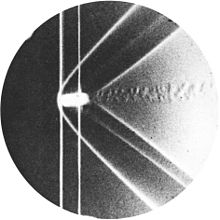
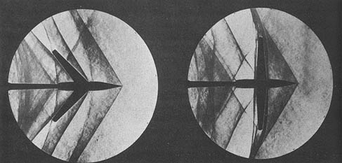
In 1887, Ernst Mach and Peter Salcher presented their seminal paper on the supersonic motion of a projectile, “Photographische Fixirung der durch Projectile in der Luft eingeleiteten Vorgänge” (“Photographic Recording of the Processes Initiated in Air by Projectiles”) in the journal Sitzungsberichte der Kaiserlichen Akademie der Wissenschaften [Wien], Mathematisch-Naturwissenschaftliche (Proceedings of the Imperial Academy of Sciences [Vienna], Mathematical and Natural Sciences Section), one of their famous schlieren photos being shown below. They theoretically predicted and experimentally confirmed the formation of a conical shock wave, commonly known as a Mach cone, at the nose of a projectile traveling at supersonic speeds. This was accompanied by an expansion wave at the tail, completing the characteristic wave pattern of supersonic motion. Note also the turbulent wake trailing behind the projectile.
In the early 1920s, Alexander Martin Lippisch proposed a series of delta-wing concepts, although not for supersonic airplanes but for unconventional “tailless” airplanes. However, by 1930, considerable interest in supersonic flight had developed, and the aerodynamics associated with supersonic flows were being studied extensively in wind tunnels. [2] Parallel theoretical studies were also underway, with Jakob Ackeret publishing a pioneering paper on the lift and drag of a supersonic airfoil in 1925.[3]
During WWII, airplane designs were driven by the need for faster airplanes, such as the P-51 Mustang and Spitfire, which could approach the speed of sound in a dive. However, the increased speeds presented a new problem, namely a strong nose-down pitching moment, where the airplane’s nose would suddenly pitch downward uncontrollably. This phenomenon was known as the “dive recovery problem” or “Mach tuck,” which sometimes made recovery from the dive impossible.[4] Additionally, advancements in aerodynamic research and understanding the physics of supersonic flight led to the development of new airplane designs, such as swept-wing configurations, ultimately allowing airplanes to operate at higher airspeeds before encountering Mach tuck and other adverse effects resulting from the compressibility of the airflow.
The aerodynamic effects of using sweep at high speeds were first investigated in Germany as early as 1935 by Albert Betz and Adolph Busemann. After that, Lippisch designed the famous rocket-powered Messerschmitt Me 163 Komet, which had a swept, almost delta wing and was powered by a rocket engine. It was the first piloted airplane of any type to approach Mach 0.9 but not quite exceed the speed of sound in level flight. This airplane was followed by the Messerschmitt Me 262, which had a swept wing and became the world’s first operational turbojet-powered fighter airplane. The Gloster Meteor was the first British jet-powered fighter and the first Allied jet aircraft to enter operational service during WWII. It first flew for the Royal Air Force in 1944, when the Luftwaffe deployed the Me 262, but saw limited combat.
The first airplane to fly supersonically in straight and level flight was the U.S.’s Bell X-1, a rocket-powered research airplane, which performed several test flights near the speed of sound immediately after WWII. The air-dropped Bell X-1, piloted by Chuck Yeager, first reached supersonic speeds in level flight in October 1947. The British were also working on supersonic airplanes. The Miles M.52 was designed in secrecy between 1942 and 1945 during WWII, with Frank Whittle‘s Power Jets being contracted to produce its turbojet engine. The M.52 design had a conical bullet-shaped nose, thin, mildly swept wings, and a tail with sharp leading edges. While this airplane never flew with a pilot, scaled models were flown supersonically in 1947.
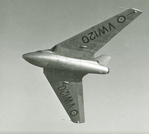
In September 1948, the tailless swept-wing de Havilland D.H.108 Swallow, as shown in the photograph below, reached just over Mach 1.0 while in a shallow dive. Unfortunately, the airplane killed its designer and pilot, Geoffrey de Havilland Jr., because of high unsteady aerodynamic-induced loads caused by shock-induced flow separation and stall, resulting in a catastrophic structural failure of the airplane. In the meantime, the U.S. continued to work on supersonic flight with variants of the X-1 (A through E models), the X-1E exceeding Mach 2 and approaching Mach 3 in September 1956.
After the fundamental challenges of aerodynamics, stability, and control, as well as propulsion, near and beyond Mach 1.0 began to be resolved by the early 1950s; it was not long before new military aircraft were designed to operate routinely at supersonic speeds. The invention of the turbojet engine, along with the development of the afterburner (or reheat), which burns additional fuel in the exhaust stream to produce increased thrust, enabled aircraft to accelerate through the transonic regime and sustain supersonic flight.
Examples include the Convair F-102 Delta Dagger and its successor, the F-106 Delta Dart, both of which employed delta wings for improved supersonic flight performance. Aircraft such as the General Dynamics F-111 and the Grumman F-14 Tomcat utilized variable-sweep wings to optimize aerodynamic efficiency across a wide range of speeds. The English Electric Lightning was capable of speeds exceeding Mach 2 in level flight and was among the first supersonic interceptors to enter military service. The Dassault Mirage III was a highly successful delta-wing aircraft that saw widespread international use. More recently, the multinational Panavia Tornado achieved significant success with its variable-geometry wings, optimized for both low-speed and supersonic flight.
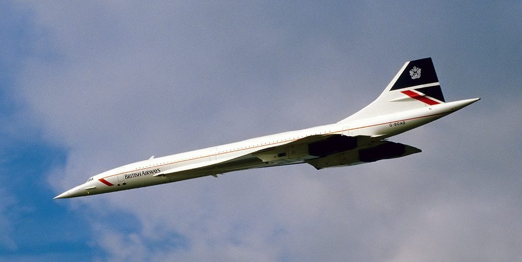
However, civil supersonic airplanes carrying fare-paying passengers have met with additional challenges. The rise and fall of the Anglo-French Concorde and the Soviet Tupolev Tu-144 provide compelling case studies on the intersection of technological capabilities and commercial viability. While the Concorde was a remarkable engineering achievement, the costs of developing a supersonic transport (SST) were enormous, and its economic viability was limited, as Boeing quickly discovered with their proposed Model 2707 SST. Furthermore, Concorde‘s loud “sonic booms” restricted its commercial flights to overwater routes, thereby limiting its ability to achieve its full economic potential, which ultimately led to the eventual discontinuation of all supersonic passenger travel in 2003.
It seems unlikely that supersonic transport airplanes (SSTs) will return to mainstream aviation anytime soon, even if technically feasible. Any revival of supersonic passenger travel must address the aerodynamic and propulsion challenges of long-range, high-speed flight, as well as the economic, environmental, and regulatory constraints that accompany it. Upstarts like Boom Supersonic face a difficult path forward, as their technological optimism and savvy marketing must ultimately contend with the rigid constraints of sound engineering, market viability, and the rigorous demands of certification. Despite sonic boom mitigation and engine efficiency improvements, persistent issues, such as high fuel consumption, operating costs, limited demand, and stringent emissions regulations, remain unresolved. Unless SSTs can achieve economic viability and environmental sustainability, as well as mitigate the intensity of sonic booms, they are unlikely to progress to commercial reality, at least for now.
Fundamentals of Supersonic Flow
In supersonic aerodynamics, the behavior of the flow encountering a body and the changes in its geometry are fundamentally different from those of subsonic flow. A key distinction arises from the fact that pressure disturbances in a supersonic flow can only propagate downstream; their upstream propagation is confined by wavefronts called Mach waves and shock waves. Consequently, a supersonic flow must adjust locally and instantaneously to geometric changes in the body shape through discontinuities.
Basic Flow Physics
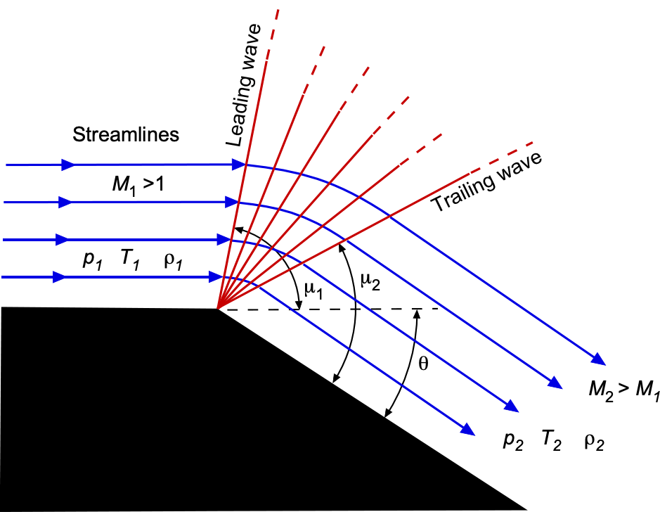
When a supersonic flow turns into itself, such as when it encounters a corner or a wedge facing upstream, the result is a compression process and the formation of a shock wave. To help explain this behavior, the schlieren flow visualization image below shows remarkable details of the Mach 2 supersonic flow about a projectile. A shock wave is formed at the nose of the projectile, which, in three dimensions, is cone-shaped and sometimes called a shock cone. The effect of this shock wave (usually referred to simply as a “shock”) is to decelerate the flow and reduce its Mach number, accompanied by an increase in static pressure and temperature. This compression in the shock is accompanied by entropy generation and a loss of total pressure and energy, making it inherently irreversible and manifesting as a source of drag called wave drag.
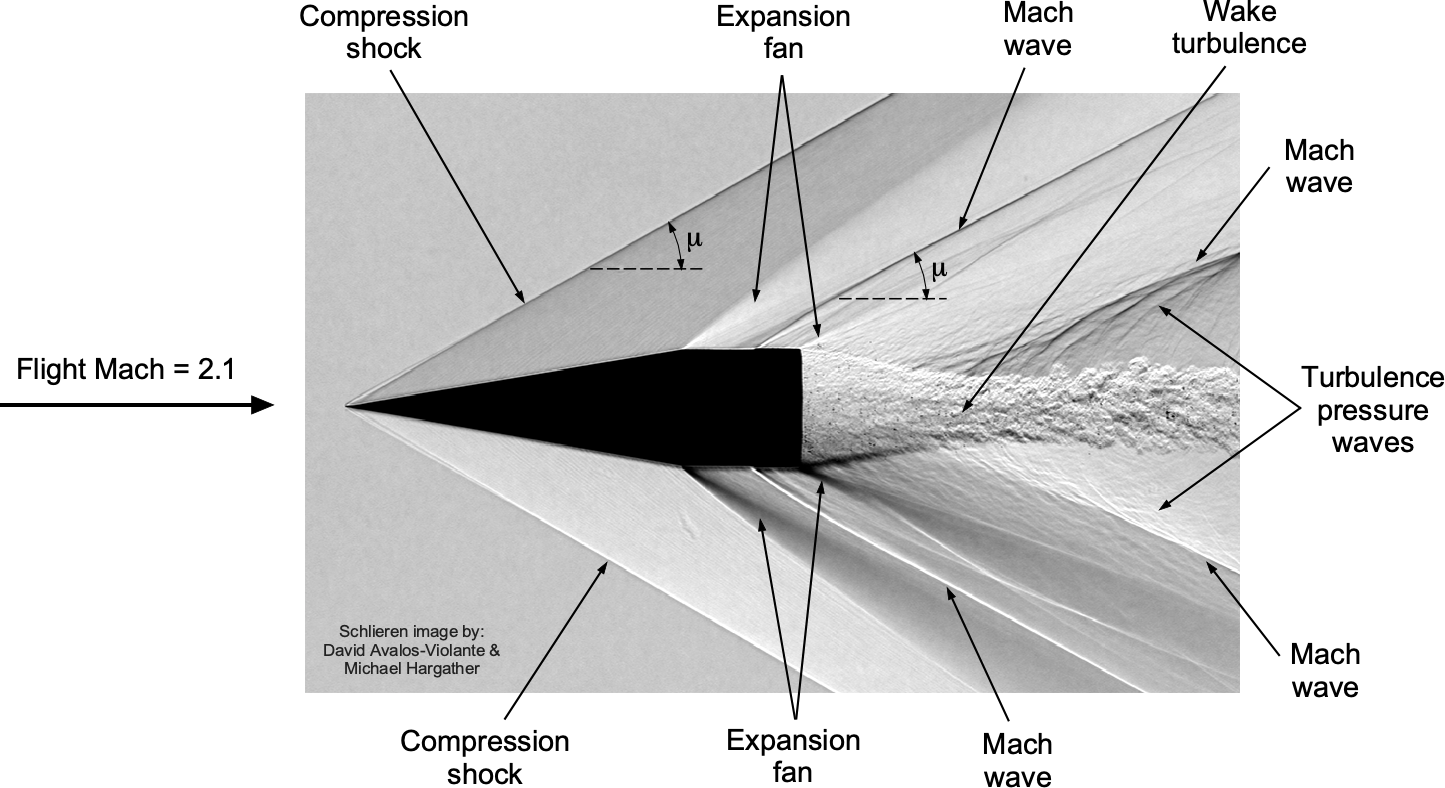
Conversely, when a supersonic flow is turned away from itself, such as around a convex corner, it undergoes an expansion process, as can also be seen in this detailed schlieren image. In this case, a shock wave cannot form. Instead, the supersonic flow adjusts smoothly through a continuous, isentropic expansion called a Prandtl-Meyer expansion “fan,” composed of an infinite number of infinitesimally weak Mach waves. These expansion waves allow the supersonic flow to turn and accelerate. Unlike compression shocks, expansion waves increase the Mach number while reducing the static pressure and temperature. Because this process is isentropic, there is no significant entropy increase, total pressure losses, or wave drag.
Notice also in the schlieren image that a small bump near the tail of the projectile generates a Mach wave. Downstream of the projectile, the flow comprises a contracting then expanding turbulent wake, the intensity of the turbulence generating a series of significant sound waves that coalesce along another set of Mach waves.
A proper understanding of the compression of the flow through shock waves and expansion through Prandtl-Meyer fans is essential for designing and analyzing high-speed aerodynamic configurations. With a supersonic wing, for example, compression and expansion waves produce the changes in pressure that give rise to lift and drag. In supersonic inlets, multiple oblique shocks compress the flow before it enters the engine. In supersonic nozzles, expansion fans are created to accelerate the flow to higher Mach numbers to produce thrust. Understanding when and how these wave systems arise and their effects on the flow is central to designing efficient supersonic vehicles and their propulsion systems, the details of which can now be exposed.
Mach Waves & Shock Waves
The terms Mach wave and shock wave (or shock) are used in many contexts of high-speed flows, so they require further distinction and elaboration. A Mach wave is an infinitesimally weak pressure disturbance that forms in supersonic flow at a specific angle known as the Mach angle,  , which depends on the Mach number of the flow,
  , and is given by
(1) 
Consider a case where a flow passes over an infinitely small bump on a flat plate, such as one located on the floor of a wind tunnel, as illustrated in the figure below. In subsonic flow, the spherically spreading pressure disturbances generated by the bump can propagate both upstream and downstream. Consequently, the flow adjusts smoothly and continuously to the presence of the bump, without producing any discontinuities or waves. However, in supersonic flow, the bump generates acoustic disturbances that cannot propagate upstream; therefore, the leading edges of the waves accumulate along a wavefront, known as a Mach wave.
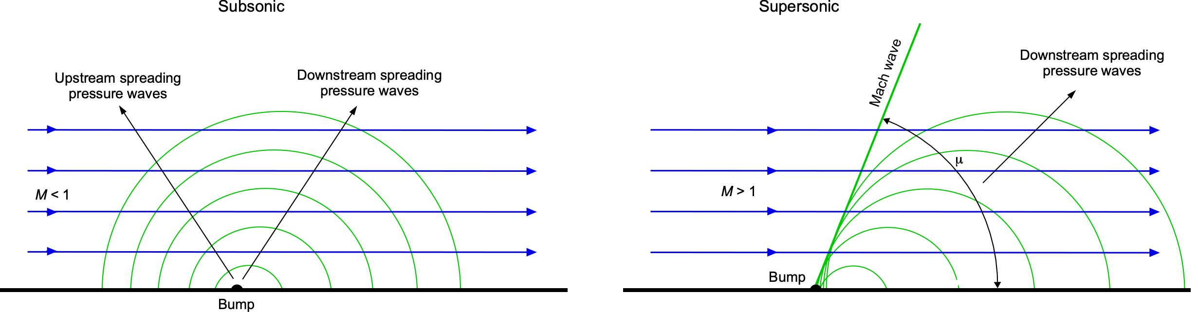
In detail, as the flow rises over the bump, it turns back on itself, producing an infinitesimally weak compression wave. As it descends, it turns away from itself, generating a weak expansion wave. In the limit as the bump becomes infinitely small, these waves manifest as a single wavefront inclined at the Mach angle , with pressure disturbances accumulating along this wavefront. This directional behavior is characteristic of linear acoustic wave propagation in supersonic flow. Notably, these weak waves are isentropic, meaning they involve no change in entropy and behave like sound waves with a leading edge boundary inclined relative to the flow direction. Therefore, Mach waves are considered reversible and non-dissipative because they do not cause significant changes in pressure, temperature, or entropy. Nevertheless, because they are associated with small but finite changes in density, they can still be visualized using schlieren or shadowgraph techniques.
In contrast, a shock wave is a finite-strength discontinuity in the flow where pressure, temperature, density, and entropy increase abruptly. Shock waves form when a finite deflection compresses the flow, typically when it turns strongly into itself. These waves are non-isentropic and irreversible, resulting in energy dissipation through entropy increases and often heating. The Mach wave limit represents the boundary between these two types of disturbances; it occurs when the flow deflection angle approaches zero and the shock wave becomes vanishingly weak. The shock angle approaches the Mach angle in this limit, and the flow transition becomes isentropic. Therefore, a shock wave effectively turns into a Mach wave, and this limit defines the weakest possible compression wave that can exist in a supersonic flow.
To better illustrate these concepts, compare infinitesimal oblique compression and expansion waves, as shown in the figure below. For the compression wave, the surface, or the “wall,” is tilted upward at a small angle,  . This configuration is referred to as a concave corner. Suppose the upstream flow is supersonic at
  as it approaches the corner. Then, after the compression wave, the value of
  is slightly lower in magnitude and inclined upward at the same angle as the surface,
  , where
  . The wave angle is denoted by
  . A streamline bends upward as it crosses this oblique wave. As
  , the angle approaches the Mach angle, . The Mach number decreases across the oblique compression wave, while pressure, density, and temperature all increase. As the angle becomes finite, the compression wave becomes a shock wave.
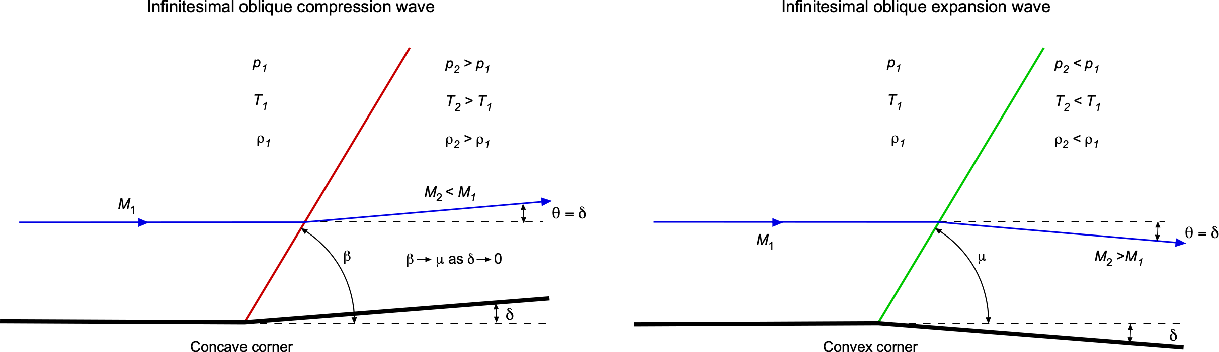
Now, consider an expansion wave. The geometry is similar, except the wall is tilted downward, forming a convex corner. Again, assume a supersonic incoming flow. The turning angle is again , but now the flow deflects downward. As , the expansion wave also approaches the Mach angle, . Across this wave, the Mach number increases, while pressure, density, and temperature all decrease, the opposite of the behavior across a compression wave. In either case, as , the wave becomes a Mach wave. Prandtl-Meyer expansion waves arise when the turning angle is finite. In that case, the flow turns smoothly through an expansion fan, a continuous collection of infinitesimal expansion waves that “fan out” from the corner, a process described next.
Compression Waves & the θ-β-M Relation
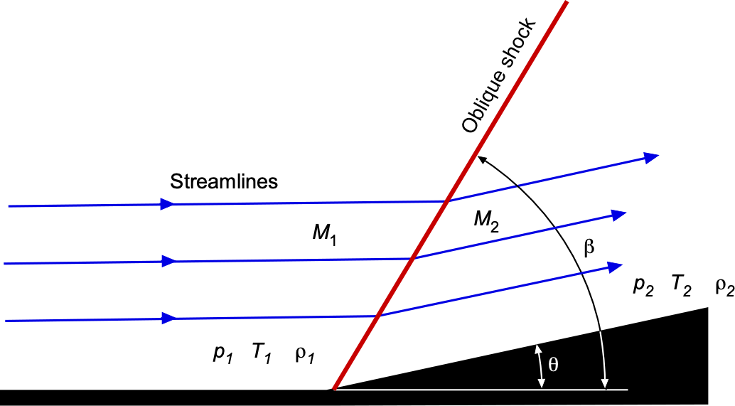
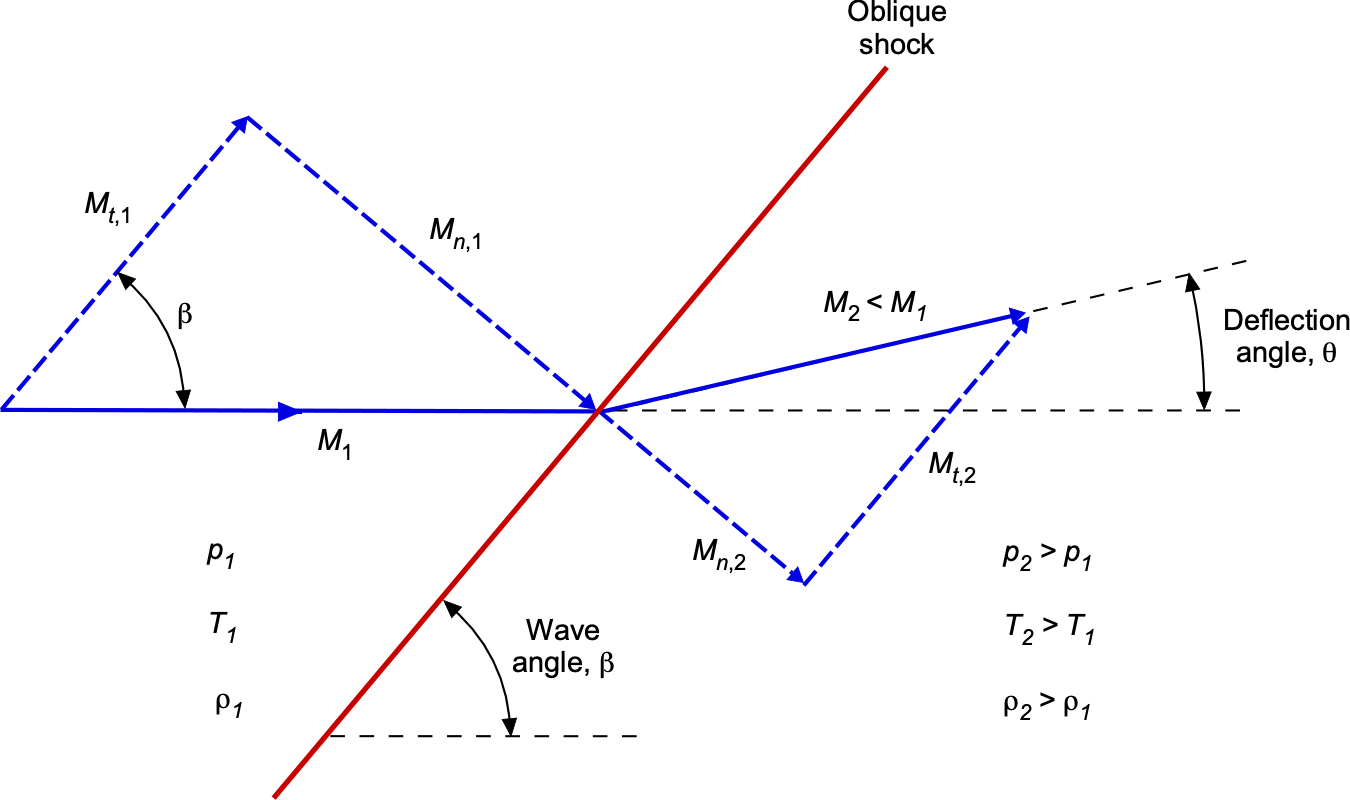
When a compression surface turns a supersonic flow with a finite angle, such as a wedge, ramp, or airfoil section, an oblique shock wave forms at an angle to the incoming flow direction, as shown in the figure below. The deflection angle , shock angle , and upstream Mach number are related through the –– relation, which is a fundamental equation in compressible aerodynamics, i.e.,
(2) 
Equation 2 arises from applying the conservation laws of mass, momentum, and energy across an oblique shock wave, and it assumes steady, two-dimensional, inviscid flow with a perfect gas. It provides the key analytical relationship needed to determine either the shock angle or the deflection angle given the upstream Mach number . In the hypersonic limit ( ), the shock angle approaches the wedge angle
  , causing the shock to almost parallel the surface and form a thin shock layer, which is the hallmark of hypersonic flows over slender bodies.
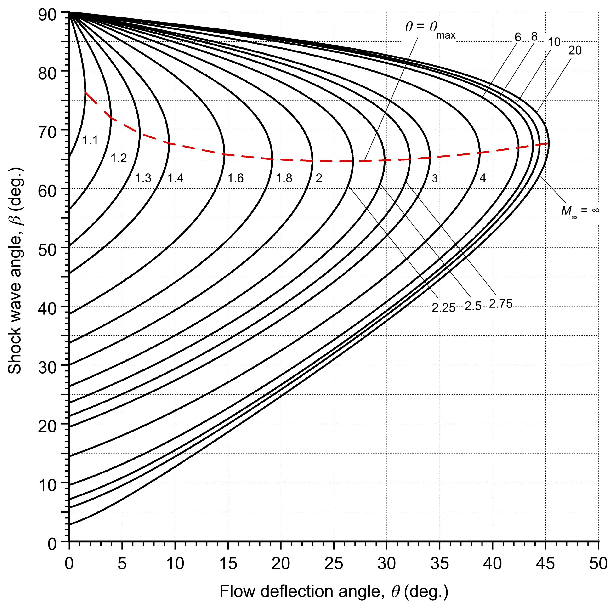
Notice that Eq. 2 is nonlinear and is typically solved graphically or numerically. A family of – curves for different Mach numbers provides quick visual insight, as shown in the figure below, and is widely used in aerodynamics and propulsion. It will be apparent that for a given upstream Mach number, , a maximum deflection angle  exists beyond which an oblique shock cannot remain attached. When
  , the shock becomes detached and forms a bow shock.
 , the shock wave angle , and the upstream Mach number
  for oblique shock waves.
It will be apparent from the plot that for each there are generally two solutions for : a weak shock (with a lower angle, with less compression and supersonic flow downstream), and a strong shock (with a higher angle and greater compression, possibly giving a subsonic flow). In practice, the weaker shock is observed because it results in lower entropy generation and is the physically realized solution.[5]
Prandtl-Meyer Expansion Theory
The behavior of supersonic flow undergoing expansion around a convex corner is governed by the Prandtl-Meyer theory. In contrast to the discontinuous nature of shock waves, the expansion process is continuous and isentropic, consisting of a fan of Mach waves that enables the flow to turn smoothly and accelerate, as shown in the figure below. Notice that for any ray in the expansion fan, the Mach angle is .
To quantify this expansion process, the Prandtl-Meyer function,  , gives the angle through which a flow must be turned to accelerate from Mach 1 to a given Mach number
(3) 
where  = 1.4 is the ratio of specific heats for air. The Prandtl-Meyer function, which has a lengthy theoretical development, is zero at Mach 1 and increases monotonically with increasing Mach number. Notice that is an angle but not a physical angle in the flow. The total turning angle required to expand a flow from an initial Mach number to a higher Mach number is given by the difference in the values of the Prandtl-Meyer function, i.e.,
(4) 
This equation allows the calculation of the downstream Mach number and turning angle for any given supersonic expansion. Because the process is isentropic, total pressure remains constant, and only the static properties, i.e., pressure, temperature, and density, decrease across the expansion fan as the Mach number increases.
If the initial upstream Mach number,  , is defined, and the desired turning angle, , is specified. then the downstream Mach number can be found by solving the nonlinear equation
(5) 
This solution is typically performed iteratively using numerical methods or by referencing a Prandtl-Meyer function table or graph, as shown below. Conversely, if both and are known, then the required turning angle can be obtained directly from  . The dashed lines in the plot below show the limiting asymptotic values as the Mach number tends to infinity, which is given analytically by
(6) 
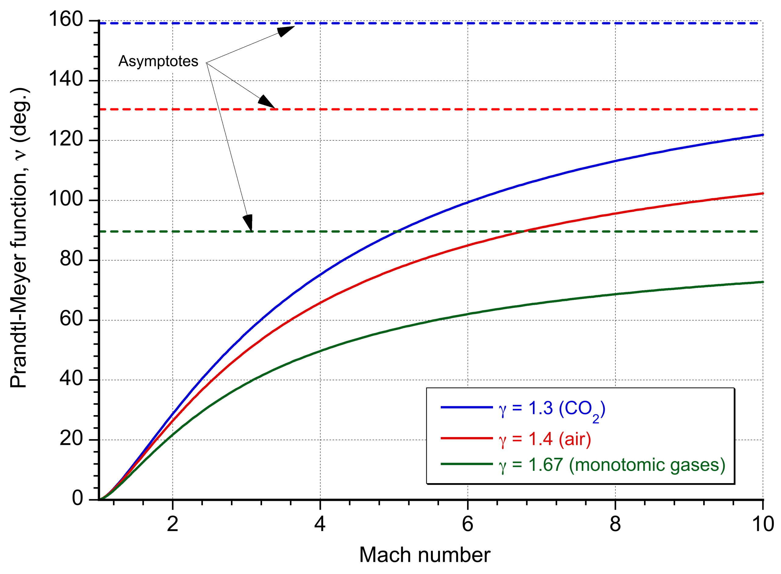
| Mach, M | ν(M) (deg.) | Mach, M | ν(M) (deg.) | Mach, M | ν(M) (deg.) | Mach, M | ν(M) (deg.) |
|---|---|---|---|---|---|---|---|
| 1.0 | 0.00 | 1.2 | 3.56 | 1.4 | 8.99 | 1.6 | 14.86 |
| 1.8 | 20.73 | 2.0 | 26.38 | 2.2 | 31.73 | 2.4 | 36.75 |
| 2.6 | 41.41 | 2.8 | 45.75 | 3.0 | 49.76 | 3.2 | 53.47 |
| 3.4 | 56.91 | 3.6 | 60.09 | 3.8 | 63.04 | 4.0 | 65.78 |
| 4.2 | 68.33 | 4.4 | 70.71 | 4.6 | 72.92 | 4.8 | 74.99 |
| 5.0 | 76.92 | 5.2 | 78.73 | 5.4 | 80.43 | 5.6 | 82.03 |
| 5.8 | 83.54 | 6.0 | 84.96 | 6.2 | 86.29 | 6.4 | 87.56 |
| 6.6 | 88.76 | 6.8 | 89.89 | 7.0 | 90.97 | 7.2 | 92.00 |
| 7.4 | 92.97 | 7.6 | 93.90 | 7.8 | 94.78 | 8.0 | 95.62 |
| 8.2 | 96.43 | 8.4 | 97.20 | 8.6 | 97.94 | 8.8 | 98.64 |
| 9.0 | 99.32 | 9.2 | 99.97 | 9.4 | 100.59 | 9.6 | 101.19 |
Prandtl-Meyer expansions play a crucial role in the design of nozzles for supersonic and hypersonic applications, where flows are expanded to achieve desired velocities. They also appear in external flows around corners and the trailing edges of supersonic airfoils, where expansion fans determine surface pressure distributions and lift.
Summary of Shock Flow Relations
Across a shock wave, the flow is no longer isentropic because entropy increases and irreversible losses occur. Therefore, the isentropic relations are no longer valid across the shock itself, and one must use the normal shock relations based on conservation of mass, momentum, and energy. For an oblique shock, these relations are applied to the normal component of the Mach number, i.e.,
(7) 
The key ratios of pressure, temperature, and density across the shock are
(8) 
The downstream Mach number is then obtained from the post-shock normal Mach number, i.e.,
(9) 
In contrast, an expansion fan involves smooth, continuous, isentropic turning of the flow. The flow remains isentropic through the expansion, so the pressure, temperature, and density ratios are
(10) 
These expressions allow for a complete description of changes in flow properties through compression shocks and expansion waves in supersonic flow.
Why is γ =1.4 for air?
In compressible flow analysis, the ratio of specific heats, denoted by , plays a critical role. For air at standard conditions, it is well known that = 1.4. But where does this number come from? The ratio (also called the adiabatic index) is defined as the ratio of the specific heat at constant pressure  to the specific heat at constant volume
  , i.e.,
![\[ \small{ \gamma = \frac{c_p}{c_v} } \]](https://eaglepubs.erau.edu/app/uploads/quicklatex/quicklatex.com-090b64eb2d72d09ac95137dadf465d7a_l3.svg "Rendered by QuickLaTeX.com")
These specific heats reflect how much energy per unit mass is needed to raise the temperature of a gas under different constraints: is at a constant volume (no boundary), and is at a constant pressure (allows expansion).
Air is primarily a diatomic gas (about 78% nitrogen and 21% oxygen), and at moderate temperatures (below approximately 1,000 K), it behaves like an ideal diatomic gas. According to the equipartition theorem, energy is shared equally among all active degrees of freedom, with each contributing  /2 per mole to the internal energy. For a diatomic gas at room temperature, there are three translational degrees of freedom and two rotational degrees of freedom. Vibrational modes are inactive at these temperatures. So that
![\[ \small{ c_v = \small \left( \frac{5}{2} \right) R } \]](https://eaglepubs.erau.edu/app/uploads/quicklatex/quicklatex.com-3329806c0d8f706cd14bd122495b6cbd_l3.svg "Rendered by QuickLaTeX.com")
Using a well-known thermodynamic relationship that
![\[ \small{ c_p = c_v + R } \]](https://eaglepubs.erau.edu/app/uploads/quicklatex/quicklatex.com-ae7b00a794b1852f59cac51f5016f0c2_l3.svg "Rendered by QuickLaTeX.com")
then becomes
![\[ \small{ \gamma = \frac{c_p}{c_v} = \frac{c_v + R }{c_v} = \small \frac{7/2}{5/2} = \frac{7}{5} = 1.4 } \]](https://eaglepubs.erau.edu/app/uploads/quicklatex/quicklatex.com-30d87ad38c9f71fc3c7f21cc8eeaf26e_l3.svg "Rendered by QuickLaTeX.com")
This value of = 1.4 is essential in compressible flows because it appears in the speed of sound, i.e.,  as well as in isentropic flow relations, shock wave equations, etc. It is used to model air as a perfect gas in subsonic and supersonic applications, as well as many hypersonic flows. However, the assumption = 1.4 becomes invalid under the following conditions:
- High temperatures (typically above 1,000 K): vibrational modes become active, increasing and reducing .
- Real gas effects: dissociation, ionization, or chemically reacting flows.
- Different gas types: monatomic gases, polyatomic gases, etc.
For example, for monatomic gases (e.g., helium), then = 5/3 = 1.67. For diatomic gases at high temperatures:  1.4. Therefore, = 1.4 is used for air because it behaves like an ideal diatomic gas with five active degrees of freedom near standard atmospheric temperatures. This approximation is foundational to many compressible flow models, including the isentropic and shock relations previously discussed. However, this assumption must be revisited at high temperatures or in chemically reacting flows.
Supersonic Airfoil Characteristics
The physics of the flows of airfoils and wings at supersonic flight conditions is significantly different from that obtained in subsonic flight, which is the reason the value of the Mach number is so crucial in classifying aerodynamic flows. In supersonic flight, the formation of shock waves and expansion waves significantly impacts the performance of the wing or airfoil. On the one hand, shock waves cause drag and increase the pressure on the wing’s surface. On the other hand, expansion waves arise when a supersonic flow is turned away from itself, reducing the pressure on the wing’s surface and creating lift. Therefore, the physics of these compressibility effects must all be carefully considered when designing airfoils and wings suitable for airplanes capable of supersonic flight.
Supersonic Airfoil Shapes
The figure below shows that a supersonic airfoil or wing typically features a sharp leading edge and relatively flat upper and lower surfaces to minimize wave drag and maximize lift production. The airfoil’s maximum thickness is critical in determining airfoil performance at supersonic speeds. The best supersonic airfoil designs are thin (i.e., low thickness-to-chord ratios) and mildly cambered, featuring specific thickness distributions and curvature to manage shock waves and regions of flow expansion. These designs focus on minimizing wave drag and optimizing the achievable lift-to-drag ratios. A diamond-wedge airfoil is a specific type of airfoil shape used in certain supersonic flight applications.
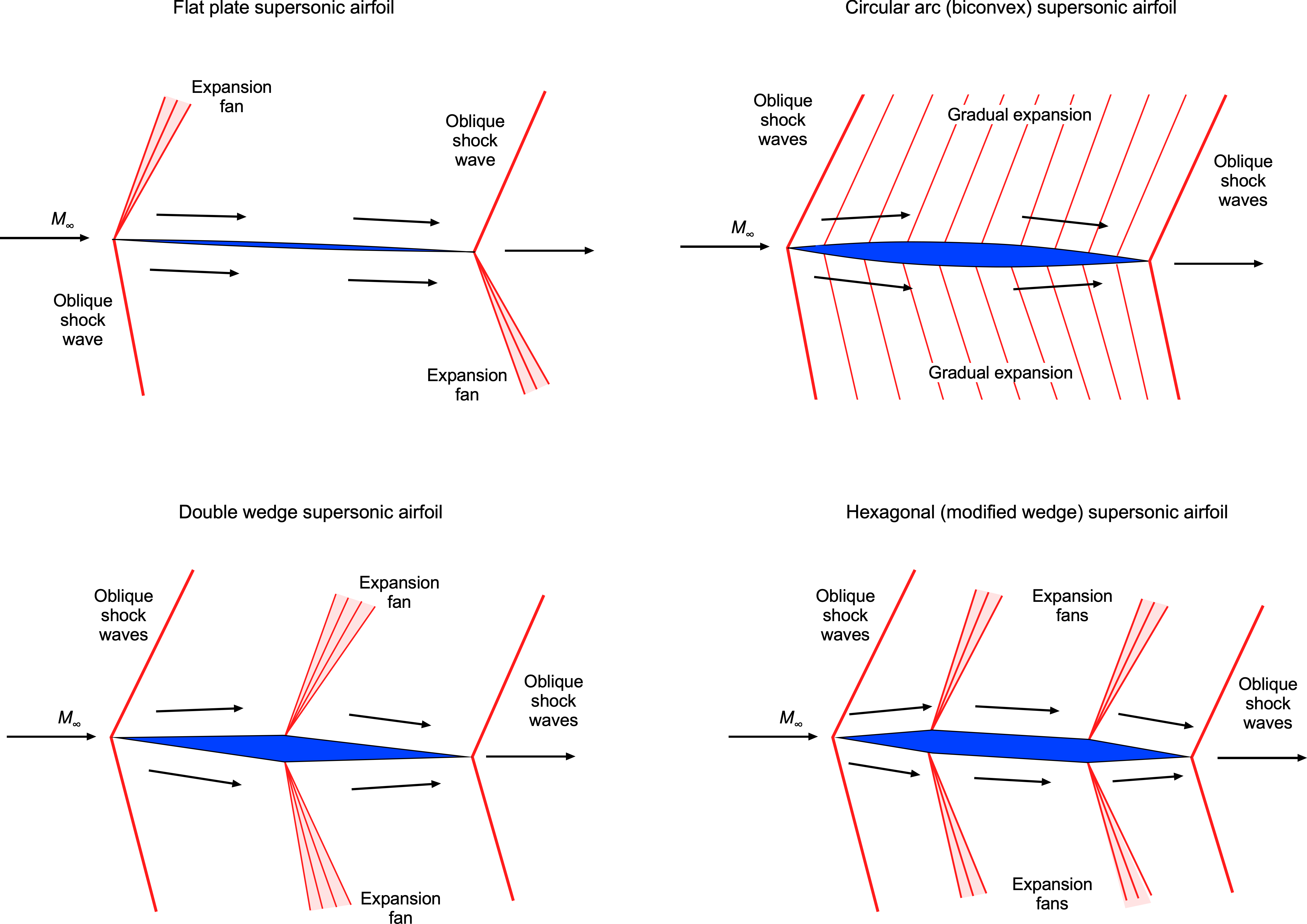
One of the key advantages of the diamond-wedge airfoil is its ability to maintain good lift-to-drag ratios over a broader range of angles of attack. They are often used for control surfaces on missiles. However, they are rarely used on the main wings of actual supersonic airplanes because of their abysmal aerodynamic performance at low Mach numbers and high angles of attack, such as during takeoff and landing. Therefore, supersonic airplanes are more likely to use thin, semi-circular arc sections, with the addition of high-lift devices for low-speed flight.
Flow Patterns & Pressure Distributions
Consider the flow about an airfoil in the form of a double-wedge or diamond shape experiencing a supersonic flow, as shown in the figure below. Notice that in a supersonic flow, the flow upstream gets no warning of the approaching airfoil, so the streamlines have no curvature. Oblique compression shock waves occur at the leading edge of the airfoil. The Mach number across the shock waves decreases (but remains supersonic), and the static pressure increases over the freestream value. Notice in the figure below that the greater pressure increase is on the lower surface, significantly contributing to the lift.
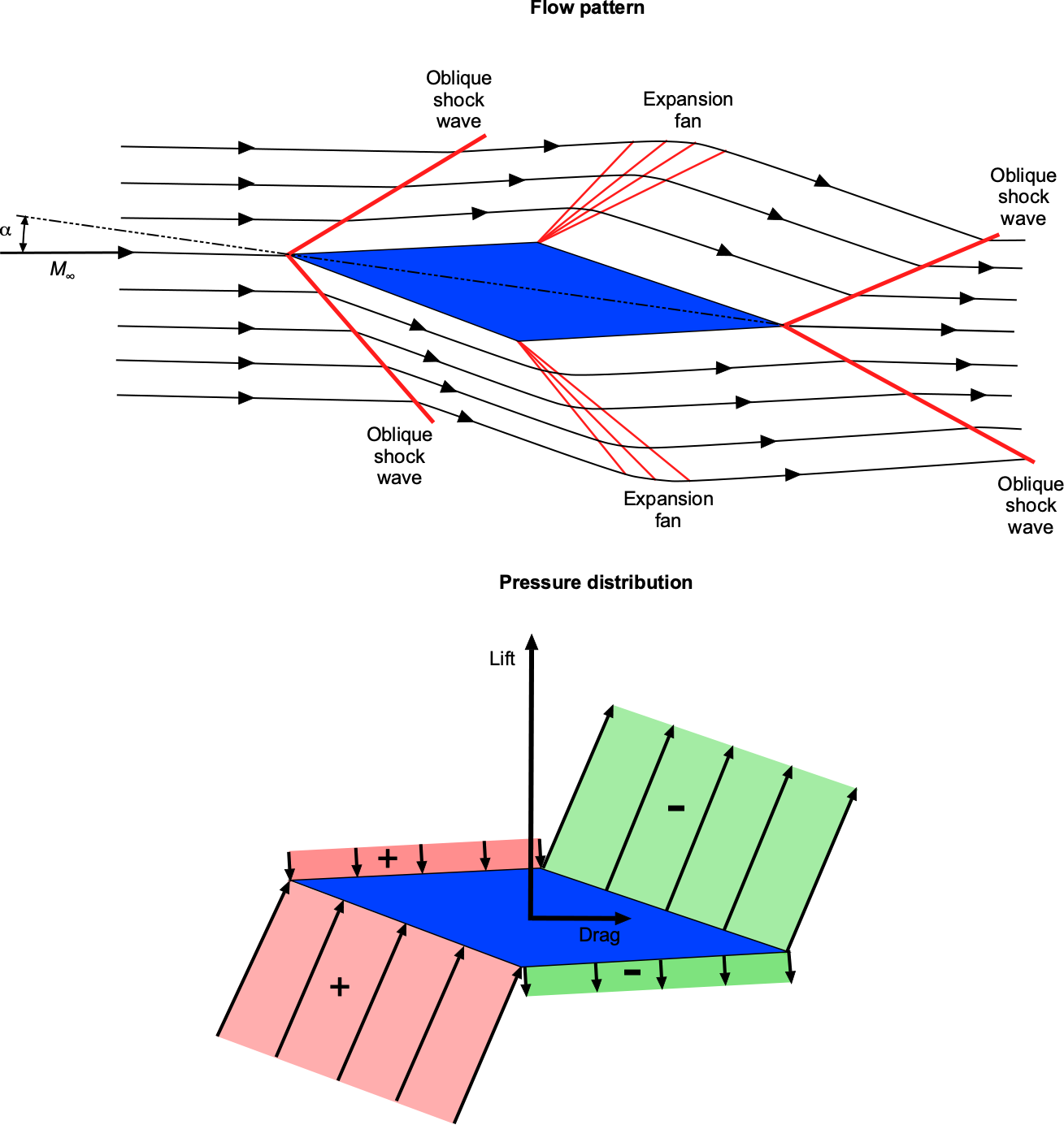
At the points of maximum airfoil thickness, expansion waves appear, which cause the Mach number to increase and the pressure to decrease after the expansion is complete. The upper surface of the airfoil now contributes to lift production. Rarefaction shock waves form at the trailing edge, increasing the Mach number and returning the pressure to the freestream value. This pressure distribution explains why the center of lift (center of pressure) is located at or near the mid-chord of a supersonic airfoil.
Check Your Understanding #1 – Supersonic flow over a double wedge
A supersonic airflow at  ,
,  = 50,000 Pa, and
  = 250 K encounters a double wedge airfoil. The first wedge deflects the flow upward by
  (compression), and the second wedge deflects the flow downward by
  (expansion). Assume air is a perfect gas with = 1.4. Determine:
- The Mach number and pressure immediately after the oblique shock, i.e., and
 , respectively.
 - The Mach number and pressure after the expansion fan, i.e., and
 , respectively.
Show solution/hide solution.
- We can use the –– relation for a compresssion wave to find the shock angle for and
 . From the graph or the equation, this gives
![\[ \beta = 36.1^\circ \]](https://eaglepubs.erau.edu/app/uploads/quicklatex/quicklatex.com-19fe9419f27ef346a7a96f3c4d7bff97_l3.svg "Rendered by QuickLaTeX.com")
Then we can compute the normal component of the Mach number using
![\[ M_n = M_\infty \sin \beta = 2.5 \sin(36.1^\circ) = 1.47 \]](https://eaglepubs.erau.edu/app/uploads/quicklatex/quicklatex.com-ed37ff1dc6936993d4480c4fcb538406_l3.svg "Rendered by QuickLaTeX.com")
The normal shock relations give the downstream normal Mach number, i.e.,
![\[ M_{n,2}^2 = \frac{1 + \dfrac{\gamma - 1}{2} M_n^2}{\gamma M_n^2 - \dfrac{\gamma - 1}{2}} = 0.74^2 \]](https://eaglepubs.erau.edu/app/uploads/quicklatex/quicklatex.com-caec23adf786887043cb22255130511e_l3.svg "Rendered by QuickLaTeX.com")
The post-shock Mach number is then
![\[ M_1 = \frac{M_{n,2}}{\sin(\beta - \theta)} = \frac{0.74}{\sin(26.1^\circ)} = 1.68 \]](https://eaglepubs.erau.edu/app/uploads/quicklatex/quicklatex.com-55258932dbcaf0fc803a65331c636784_l3.svg "Rendered by QuickLaTeX.com")
The pressure ratio across the shock is
![\[ \frac{p_1}{p_\infty} = 1 + \frac{2\gamma}{\gamma + 1}(M_n^2 - 1) = 2.21 \]](https://eaglepubs.erau.edu/app/uploads/quicklatex/quicklatex.com-c566ffa32d4d4e1a7fc9aae9e4f3e62e_l3.svg "Rendered by QuickLaTeX.com")
so that
![\[ p_1 = 2.21 \times 50,000 = 110,500 \text{ Pa} \]](https://eaglepubs.erau.edu/app/uploads/quicklatex/quicklatex.com-f7e38c868cecc7d4d7c038b96d7ec148_l3.svg "Rendered by QuickLaTeX.com")
- Using the Prandtl-Meyer expansion function, then
![\[\]](https://eaglepubs.erau.edu/app/uploads/quicklatex/quicklatex.com-b40a4d53f62082f3e685154172b5de44_l3.svg "Rendered by QuickLaTeX.com")
![\[ \nu(M_1 = 1.68) = 21.4^\circ \quad \Rightarrow \quad \nu(M_2) = \nu(M_1) + 7^\circ = 28.4^\circ \]](https://eaglepubs.erau.edu/app/uploads/quicklatex/quicklatex.com-a204e07ef5900714261516e0e062f2fe_l3.svg "Rendered by QuickLaTeX.com")
Inverting the function numerically or using tables, then
![\[ M_2 = 2.02 \]](https://eaglepubs.erau.edu/app/uploads/quicklatex/quicklatex.com-d84b4faff5b0883cbf6bccdeef8b31c8_l3.svg "Rendered by QuickLaTeX.com")
Using the isentropic relation for pressure gives
![\[ \frac{p_2}{p_1} = \left( \dfrac{1 + \frac{\gamma - 1}{2} M_1^2}{1 + \dfrac{\gamma - 1}{2} M_2^2} \right)^{\gamma/(\gamma - 1)} = 0.53 \]](https://eaglepubs.erau.edu/app/uploads/quicklatex/quicklatex.com-0dfee6c929b78a72a5c630205327dac9_l3.svg "Rendered by QuickLaTeX.com")
so that
![\[ p_2 = 0.53 \times 110,500 = 58,500 \text{ Pa} \]](https://eaglepubs.erau.edu/app/uploads/quicklatex/quicklatex.com-b9bad41bf532a992d6492140e5290eab_l3.svg "Rendered by QuickLaTeX.com")
Lift & Drag Characteristics
For a thin airfoil in incompressible flow (i.e., linearized thin airfoil theory below stall), the relationship between the lift coefficient,  , and angle of attack,
  , is given by
(11) 
where the lift-curve slope,  , is equal to
  per radian of angle of attack. For linearized subsonic flow, the relationship changes to
(12) 
where  is known as the Glauert factor. Therefore, it is apparent from Eq. 12 that the lift-curve slope continuously increases in subsonic flow with increasing Mach number. Hover, notice that this result becomes singular as
  approaches one, which is one limitation of the linear theory.
For linearized supersonic flow, the relationship between the lift coefficient and angle of attack is given by
(13) 
This result shows that the lift-curve slope is lower in supersonic flight and decreases as the Mach number increases.
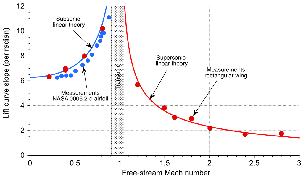
The results in Eq. 11 and 13 are considered classical solutions in the airfoil theory and allow the determination of the lift coefficients on airfoils at small angles of attack. These thin airfoil approximations agree well with measurements made on thin two-dimensional airfoils, as shown in the figure below. They also have good validity when extended to three-dimensional flow, such as when predicting the lift-curve slope of a finite wing, particularly where the sections behave in a two-dimensional manner. However, for supersonic wings, the regions influenced by subsonic versus supersonic flow still need to be considered.
The linearized supersonic airfoil theory shows that the lift coefficient is independent of the airfoil shape. Indeed, the lift coefficient produced by a supersonic airfoil at a given angle of attack is the same for a flat plate, a diamond-wedge airfoil, or a biconvex airfoil. The drag, however, is different because the dominant source of drag is wave drag, which depends strongly on the details of the airfoil shape.
For a flat plate airfoil, the wave drag coefficient,  , is
, is
(14) 
and for a diamond-wedge airfoil with a half angle,  , then
(15) 
If the chord of the airfoil is  , with a maximum thickness
  at mid-chord (i.e., at
  , then from the geometry of the wedge then
(16) 
Therefore, Eq. 15 can be written as
(17) 
which shows that wave drag increases with the square of the airfoil thickness. The wave drag of a biconvex airfoil with small concavity (i.e., a large radius of curvature) is
(18) 
In general, the wave drag of a supersonic airfoil can be expressed as
(19) 
where  is its maximum thickness-to-chord ratio and is its maximum camber. The values of the constants
  and
and  will depend on the exact shape of the airfoil.
Nevertheless, regardless of the shape, one of the most interesting and essential characteristics of an airfoil operating in supersonic flow is that its wave drag is proportional to the square of its thickness-to-chord ratio and the square of its camber. Therefore, it becomes clear why the airfoils used on the wings of supersonic airplanes must be very thin and mildly cambered compared to those used on subsonic airplanes.
Check Your Understanding #2 – Lift-to-drag ratio of a supersonic airfoil.
At what angle of attack is the maximum lift-to-drag ratio obtained for a diamond-wedge supersonic airfoil with a wedge half angle ?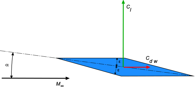
Show solution/hide solution.
The lift coefficient for a diamond-wedge airfoil is given by
![\[ C_l = \frac{4}{\sqrt{M_{\infty}^2 - 1}} \, \alpha \]](https://eaglepubs.erau.edu/app/uploads/quicklatex/quicklatex.com-f67b1bafebbb1c7cb651d5d0d6c37788_l3.svg "Rendered by QuickLaTeX.com")
and the wave drag coefficient by
![\[ C_{d_{w}} = \frac{4 \left( \alpha^2 + \epsilon^2 \right) }{\sqrt{M_{\infty}^2 - 1}} \]](https://eaglepubs.erau.edu/app/uploads/quicklatex/quicklatex.com-e00a112d093944e193ccd71536ca896b_l3.svg "Rendered by QuickLaTeX.com")
Therefore, the lift-to-drag ratio is
![\[ \frac{C_l}{C_{d_{w}}} = \frac{\alpha}{(\alpha^2 + \epsilon^2)} \]](https://eaglepubs.erau.edu/app/uploads/quicklatex/quicklatex.com-5d957a587179abe3ed0ec811fd99ec7b_l3.svg "Rendered by QuickLaTeX.com")
Differentiation with respect to gives
![\[ \frac{d (C_l/C_{d_{w}})}{d \alpha} = \frac{\epsilon^2 - \alpha^2}{(\alpha^2 + \epsilon^2)^2} \]](https://eaglepubs.erau.edu/app/uploads/quicklatex/quicklatex.com-83bb4b969a26b2eaae39c531708444d7_l3.svg "Rendered by QuickLaTeX.com")
which must be equal to zero for a maximum or minimum, i.e.,
![\[ \frac{\epsilon^2 - \alpha^2}{(\alpha^2 + \epsilon^2)^2} = 0 \]](https://eaglepubs.erau.edu/app/uploads/quicklatex/quicklatex.com-d4c6377f0cd507c4aa402c1766d0f2df_l3.svg "Rendered by QuickLaTeX.com")
Therefore, the result is  . Substituting back gives the maximum lift-to-drag ratio as
![\[ \left. \frac{C_l}{C_d} \right\rvert_{\rm max} = \frac{1}{2 \epsilon}~\mbox{~at $\alpha = \epsilon$} \]](https://eaglepubs.erau.edu/app/uploads/quicklatex/quicklatex.com-b265512f65e4c369b385a81a6b26bbc2_l3.svg "Rendered by QuickLaTeX.com")
Pitching Moments
Another interesting characteristic of a supersonic airfoil (or wing) is that its aerodynamic center of pressure approaches the mid-chord location. In contrast, a subsonic airfoil is closer to the quarter-chord. The center of pressure location for a supersonic airfoil can be expressed as
(20) 
which is independent of the Mach number. The actual location depends on the camber and angle of attack, but quickly approaches mid-chord for even low angles.[6] For a flat plate airfoil, the center of pressure is exactly at mid-chord.
The practical upshot of this is that a wing (or airplane) transitioning from subsonic to supersonic flight experiences a significant aft movement of its aerodynamic center. As shown in the figure below, this effect can produce a sizeable nose-down pitching moment about the airplane’s center of gravity. This fundamental change in aerodynamics has severe implications for the longitudinal pitch stability of a supersonic airplane as it transitions between subsonic and supersonic flight conditions.[7]
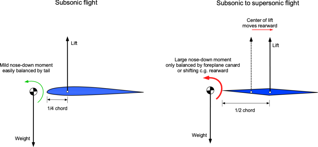
Today, designers can balance out these moments using aerodynamic forces, such as from a foreplane canard on some supersonic fighter airplanes or by pumping a specific weight of fuel to the trim tanks further aft inside the wings to gain the proper location of the center of gravity, such as was done with the fuel system on Concorde.
Check Your Understanding #3 – Calculation of the lift-to-drag ratio of a supersonic airfoil.
A supersonic double-wedge airfoil with a thickness-to-chord ratio of 10% is operated at an angle of attack of 5.5 degrees at a Mach number of 2.5. For these conditions, calculate the lift and drag coefficients, the lift-to-drag ratio, and the moment coefficient about the leading edge.
Show solution/hide solution.
In this case, the values given lead to
![\[ \sqrt{M_{\infty}^2 - 1} = \sqrt{2.5^2 - 1} = 2.291 \]](https://eaglepubs.erau.edu/app/uploads/quicklatex/quicklatex.com-33c2cd4158d84434c01055b57794518f_l3.svg "Rendered by QuickLaTeX.com")
and
![\[ \alpha = 5.5 \times \frac{\pi}{180} = 0.096~\mbox{rads} \]](https://eaglepubs.erau.edu/app/uploads/quicklatex/quicklatex.com-f72ff5c318521758f60e4413c38e645e_l3.svg "Rendered by QuickLaTeX.com")
The lift coefficient is
![\[ C_l = \frac{4 \, \alpha }{\sqrt{M_{\infty}^2 - 1}} = \frac{ 4 \times 0.096}{2.291} = 0.168 \]](https://eaglepubs.erau.edu/app/uploads/quicklatex/quicklatex.com-3442571729c810d4e9643dd455dd1caf_l3.svg "Rendered by QuickLaTeX.com")
The wave drag coefficient is
![\[ C_{d_{w}} = \frac{4}{\sqrt{M_{\infty}^2 - 1}} \bigg( \alpha^2 + \left( \frac{t}{c} \right)^2 \bigg) = \frac{4.0}{2.291} \left( 0.096^2 + 0.1^2 \right) = 0.0336 \]](https://eaglepubs.erau.edu/app/uploads/quicklatex/quicklatex.com-2c69481563b794d5c3e9565fba93d825_l3.svg "Rendered by QuickLaTeX.com")
Therefore, the lift-to-drag ratio is
![\[ \frac{C_l}{C_{d_{w}} } = \frac{0.168}{0.0336} = 5.0 \]](https://eaglepubs.erau.edu/app/uploads/quicklatex/quicklatex.com-3013b943a25da9f3febe4579c09915fb_l3.svg "Rendered by QuickLaTeX.com")
The pitching moment coefficient about the leading edge will be
![\[ C_{m_{\rm le}} = -\frac{x_{\rm cp}}{c} \, C_l = -0.5 \times 0.168 = -0.085 \]](https://eaglepubs.erau.edu/app/uploads/quicklatex/quicklatex.com-cac15f572cfffac5bd4efd217583e6c8_l3.svg "Rendered by QuickLaTeX.com")
The minus sign denotes a nose-down moment.
Supersonic Finite Wings
Interest in the theory and practice of supersonic flight continued at various research centers such as the NACA, with wind tunnel tests confirming the development of the high drag on an airplane in supersonic flight, which had been known as the “sound barrier.” Although Mach 1 is not a barrier per se, these conditions result in significant changes in the flow physics of the airplanes that can affect their flight performance, stability, and control characteristics.
After the work of Betz and Busemann before WWII, Robert T. Jones at NACA Langley developed an aerodynamic theory for supersonic delta wings, his work “Wing Plan Forms for High-Speed Flight” being published as NACA TR-863 in 1947. His approach combined the theory of thin supersonic airfoils with highly swept delta wings. This wing design became the basis for the first generation of supersonic delta-wing airplanes.
Subsequently, several different supersonic airplane prototypes were built and flown by American and British manufacturers, including the Convair XF-92 and the Fairey Delta 2, the latter setting a new World air speed record on 10 March 1956, achieving Mach 1.73. However, such airplanes did not always have good handling qualities and required high landing speeds. Consequently, there were many mishaps with the first generation of supersonic airplanes, including stall/spin events and other departures from controlled flight, often resulting in fatalities. In this regard, the Lockheed F-104 Starfighter became one of the most notorious among other jet fighter airplanes.
Mach Angle
As an airplane flies faster and approaches Mach 1, pressure disturbances produced by the airplane begin to merge, and a strong compression wave forms in front of the airplane. As the airplane becomes supersonic, this wave becomes a single wavefront called a shock wave. In three dimensions, this shock wave is called a Mach cone, which extends back from the nose of the airplane, as shown in the schematic below.
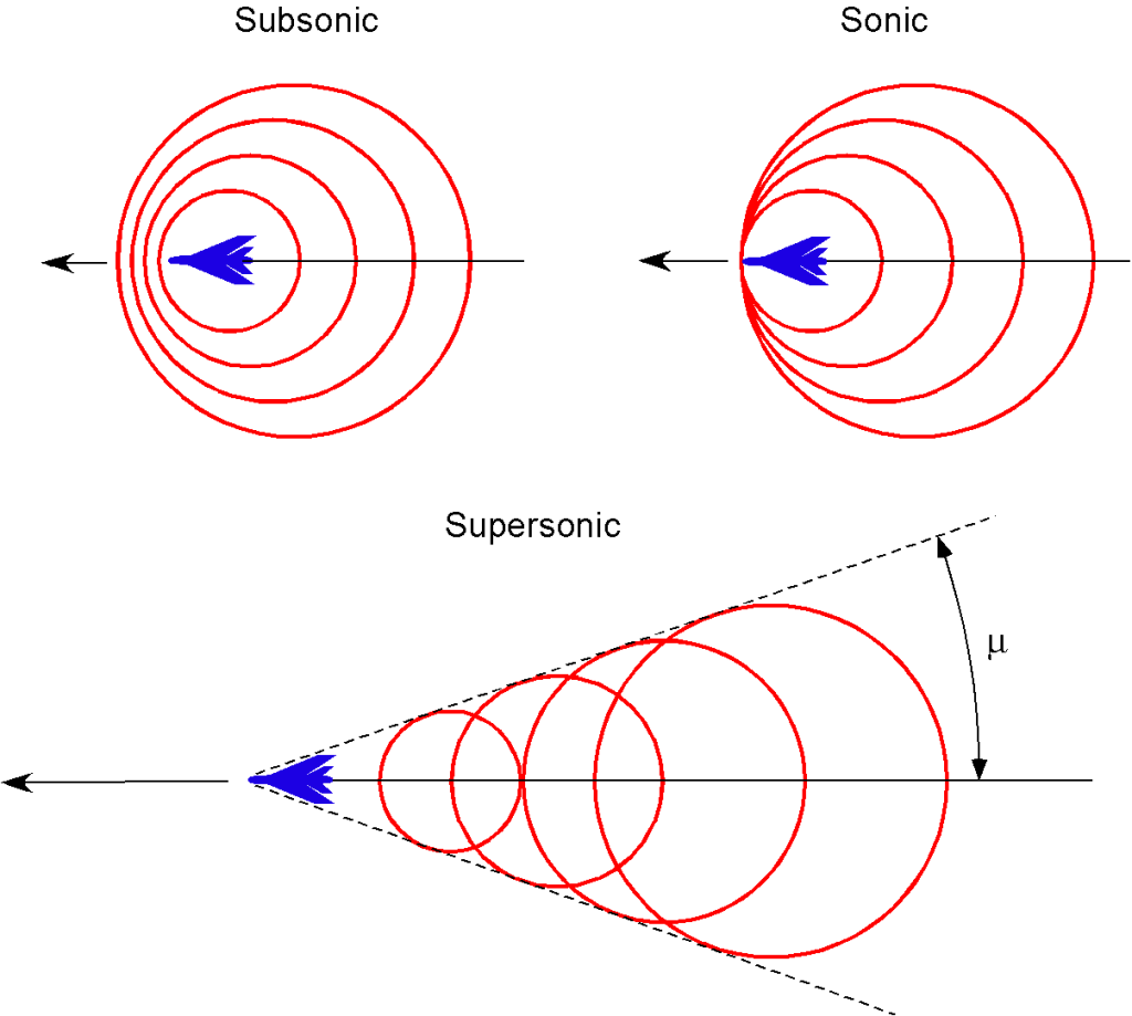
The figure below shows schlieren visualization images of the supersonic flow about a model of a fighter airplane in a wind tunnel. Notice the build-up in the number and intensity of the almost normal shock waves as Mach 1 is approached. In supersonic flight, the Mach cone becomes increasingly swept back with increasing flight Mach number, . The angle is used to denote the Mach angle, as given by
(21) 
which is the half-apex angle of the Mach cone.

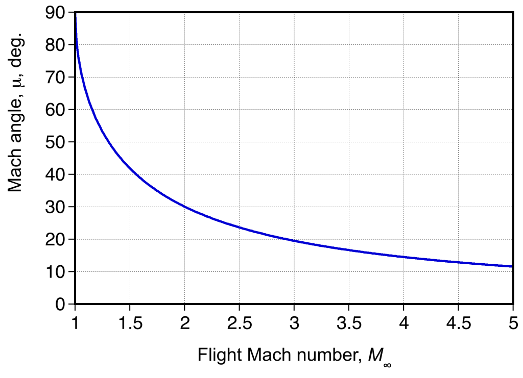
Therefore, the Mach angle is 90 at
at  , and its value decreases quickly beyond Mach 1, as shown in the figure below. Notice that even by a Mach number of 2, the Mach cone is already swept back 60 to a half apex angle of
  . For hypersonic speeds, the Mach angle is so steep that sweeping the wing behind the Mach cone so it cannot touch the body’s surfaces is impractical. Therefore, a blunt or bluff body shape is often a better design solution to keep the shock waves away from the surfaces.
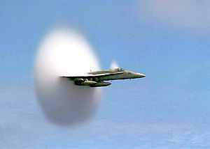
In the figure below, the signature of the shock waves and Mach cone can also be seen through the natural condensation of water vapor in the air in the lower pressure and slightly lower temperature regions produced over the airplane. In this case, only the signature of the expansion shock is made, the compression shock increasing the air temperature. This effect occurs only with humid air conditions, and the lighting must also be suitable to capture such an image.
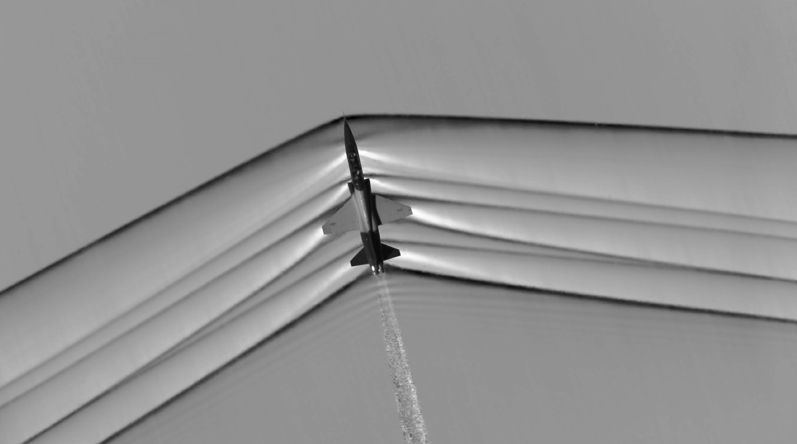
The photograph below is a fascinating schlieren image of the plethora of Mach (shock) waves generated by an actual airplane during supersonic flight. The optical method for visualizing this flow is called Airborne Background Oriented Schlieren (ABOS), the light source is the sun, and the image is taken from a chase airplane. Notice the particularly strong (i.e., darker-looking) Mach waves at the nose and tail of the airplane, which are those responsible for the sonic booms heard on the ground. Also apparent in this image is the turbulence from the engine exhaust.
Check Your Understanding #4 – Flight Mach number of an airplane from the shock wave angle
The half-angle of the conical shock wave formed by a supersonic jet fighter is 25 degrees. What is the flight Mach number of the airplane? What is the airplane’s true airspeed if the local air temperature is -20oC?
Show solution/hide solution.
The half apex angle of the Mach cone angle, , is given by
![\[ {}\mu = \sin^{-1} \left( \frac{1}{M_{\infty}} \right) \]](https://eaglepubs.erau.edu/app/uploads/quicklatex/quicklatex.com-279bbe013907035bc2e3b9888d5a3e17_l3.svg "Rendered by QuickLaTeX.com")
Therefore,
![\[ M_{\infty} = \frac{1}{\sin \mu} = \frac{1}{\sin 25^{\circ}} = 2.36 \]](https://eaglepubs.erau.edu/app/uploads/quicklatex/quicklatex.com-82f1b5e9fecf8aaa8985bc59e1282bd1_l3.svg "Rendered by QuickLaTeX.com")
The absolute temperature,  , is -20 + 273.15 = 253.15K, so the speed of sound is
![\[ a_{\infty} = \sqrt{\gamma \, R \, T_{\infty} } = \sqrt{ 1.4 \times 287.057 \times 253.15} = 318.96~\mbox{m/s} \]](https://eaglepubs.erau.edu/app/uploads/quicklatex/quicklatex.com-9e4cc011d96d4646e8d7c2c210d70d4d_l3.svg "Rendered by QuickLaTeX.com")
Therefore, the true airspeed of the jet airplane is
![\[ V_{\infty} = a_{\infty} M_{\infty} = 318.96 \times 2.36 = 752.75~\mbox{m/s} \]](https://eaglepubs.erau.edu/app/uploads/quicklatex/quicklatex.com-d9652730e06c12a3bc085e79eabcaa18_l3.svg "Rendered by QuickLaTeX.com")
Wing Sweep
The Mach angle is essential in supersonic wing design because pressure disturbances in a supersonic flow are confined to the cone region as determined by the Mach angle. Unlike a subsonic flow, there is no upstream influence beyond the Mach cone in a supersonic flow; pressure disturbances are only transmitted along the length of the Mach cone and downstream. The consequence of this fact is important because if the wing’s leading edge is swept back behind the Mach cone, then the wing experiences relatively lower drag (i.e., low wave drag), as shown in the schlieren images below. Otherwise, if the shock wave reaches the wing, the shock’s effects will disrupt the flow in the boundary layer, increasing drag and possibly causing flow separation.
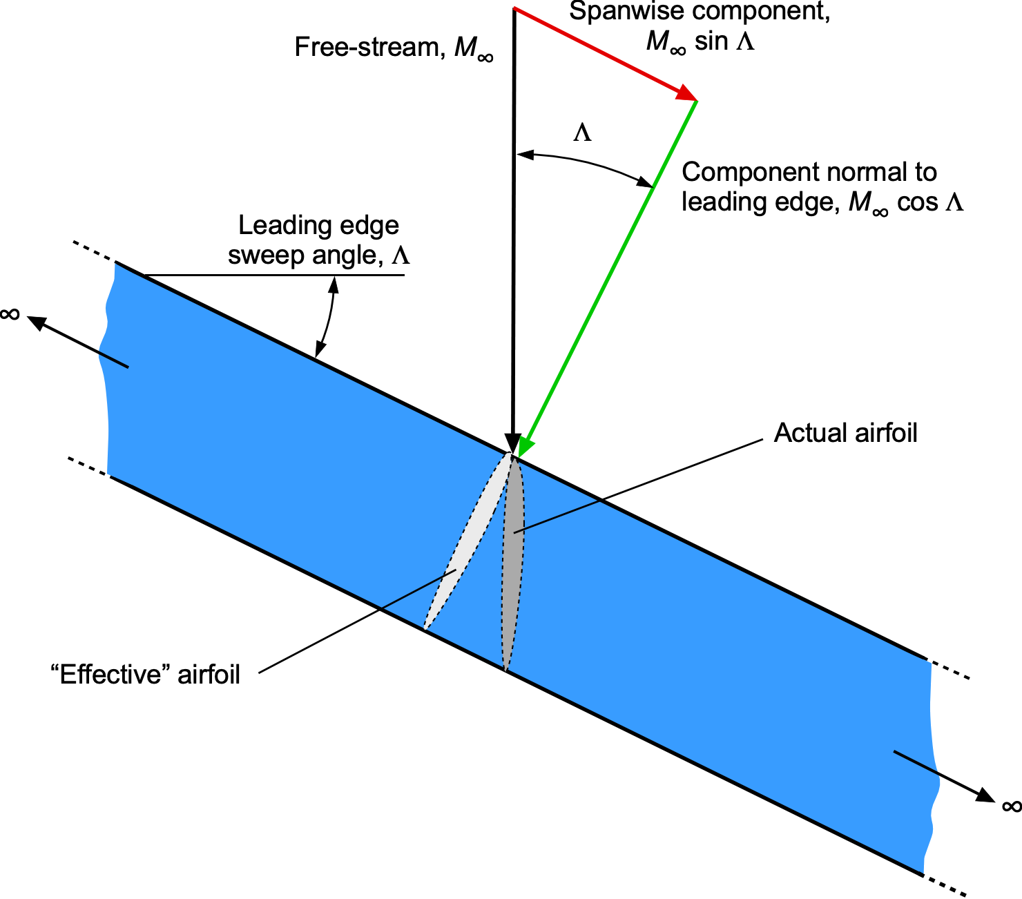
Consider a thin wing of infinite span, as shown in the figure below. The wing’s leading edge is swept back at an angle  between the freestream Mach number and the component of the Mach number normal to the leading edge. The normal component,
  , affects the wing’s chordwise pressures and aerodynamic loading; the spanwise component
  is assumed to have no effect on the flow developments over the wing. This result is called the independence principle of sweep, or simply the independence principle, after Adolf Busemann. Notice also that the “effective” airfoil shape affected by the flow has a longer chord and a lower thickness-to-chord ratio, thereby increasing the critical Mach number.
Consider the figure below, which shows a two-dimensional section of a wing with subsonic and supersonic flows. If the component is less than unity, then the chordwise pressures and wing loadings will be the same as those produced on an unswept wing in a freestream Mach number of , i.e., in a subsonic freestream. Point Q will be inside the Mach cone from all points such as P, and the flow about the wing will be subsonic, which is called a subsonic leading edge, i.e.,
(22) 
which means
(23) 
so  . The wave drag, therefore, will be zero.
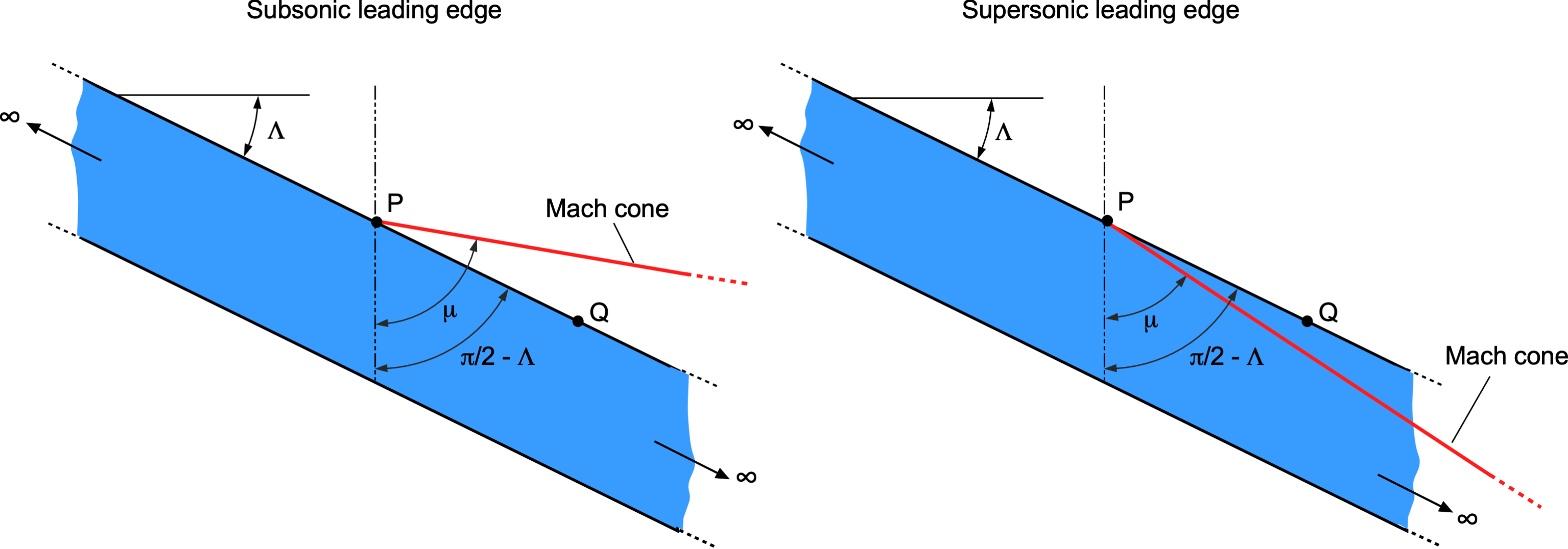
If the component is greater than unity, then the chordwise pressures and wing loadings will be the same as those on an unswept wing in a supersonic freestream of Mach number . In this case, point Q is outside the Mach cone from all points such as P, and the wing is said to have a supersonic leading edge, i.e.,
(24) 
which means
(25) 
so  . Therefore, it becomes clear that a wing flying with a supersonic leading edge will create a larger wave drag.
Therefore, a desirable design goal is to use a subsonic leading edge, which forms a series of oblique shock waves to slow the airflow gradually. If obtained, the result is a smoother transition and reduced drag rise compared to the abrupt changes associated with normal shock waves in supersonic flow. These preceding arguments, however, only apply to a wing of infinite span, which in practice means any part of a finite span wing where the flow can be considered nominally two-dimensional, i.e., away from the wing tips.
Using wing sweepback to reduce (wave) drag is most effective for larger aspect ratio wings because using too much sweep also reduces the effective aspect ratio of the wing. The disadvantage of using sweepback is that it produces less lift at a given angle of attack because of the lower effective freestream velocity normal to the wing’s leading edge, which increases the airplane’s stall airspeed. The lower effective aspect ratio results in higher induced drag on the wing during subsonic operation, which is not a desirable flight condition. Nevertheless, the wing must fly at lower airspeeds and higher angles of attack during takeoff and landing.
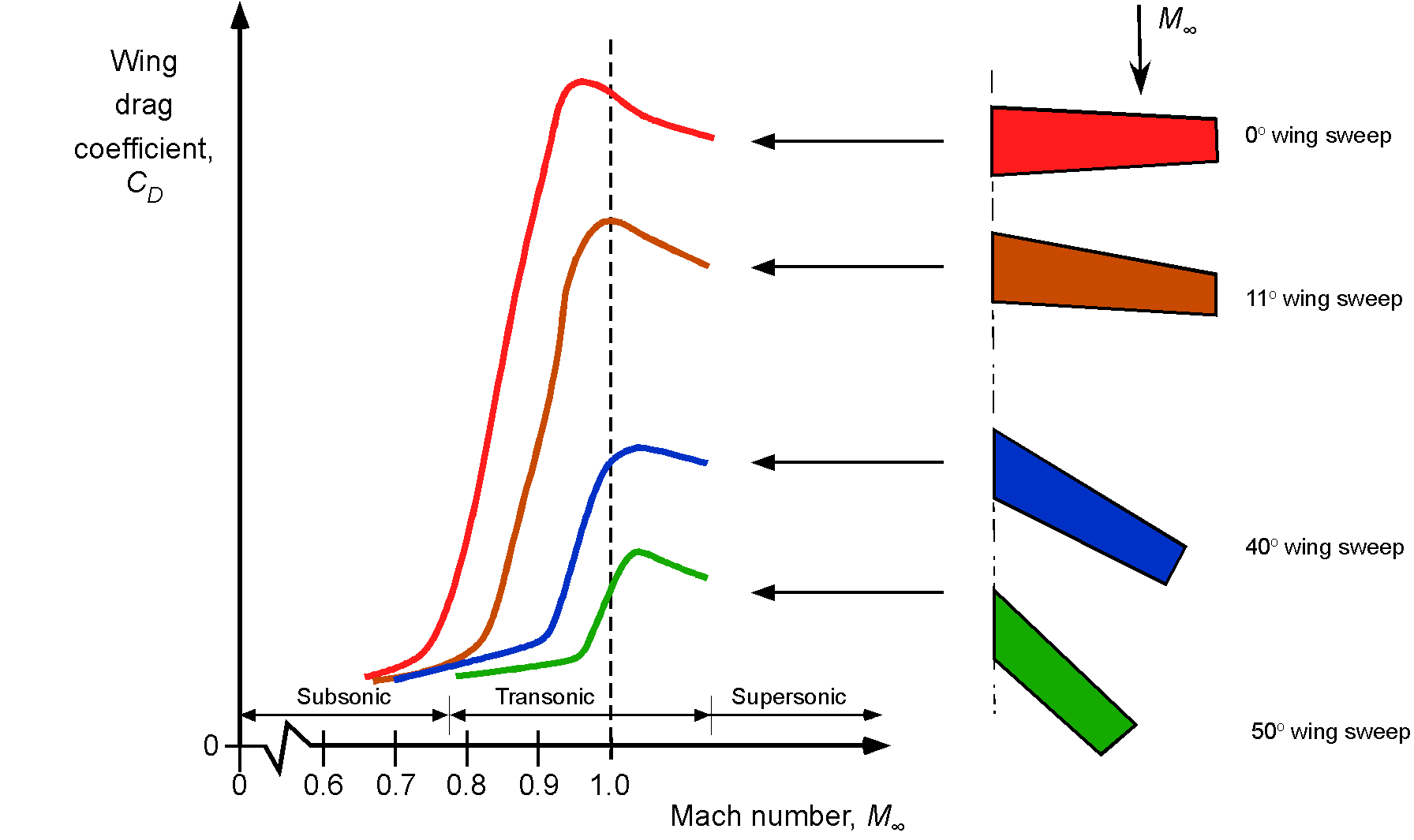
The figure below, derived from wind tunnel measurements, summarizes how wing sweep angle profoundly affects high subsonic, transonic, and supersonic drag. As is now apparent, this effect arises because swept-back wings reduce the wave drag and prevent the shock waves from interfering with the flow over the wings, which can create flow separation and a further increase in drag. Notice that sweep delays the rise of the transonic drag and reduces the rate at which the drag increases in the transonic regime. However, although swept wings can help delay this drag rise from compressibility effects, other aerodynamic, higher structural weight, and aeroelastic problems can also be associated with swept wings. Therefore, in practice, airplane designers tend to use as little wing sweep as possible to accomplish the aerodynamic goals, with 20 to 30 degrees of sweep being typical of modern commercial jet airliners.
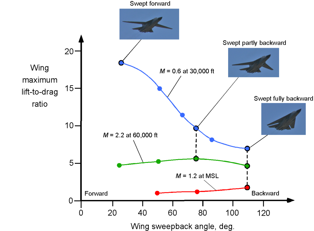
The effects of sweep angle are also summarized in the figure below, which shows the lift-to-drag ratio of a swept wing versus an unswept wing as a function of flight Mach number. In light of the preceding analysis, it becomes clear why some sweepback of a wing can minimize transonic and supersonic drag. On the one hand, as an airplane with an unswept wing approaches Mach 1, its drag increases rapidly, and its lift-to-drag ratio plummets immediately. On the other hand, it can be seen that the highly swept delta wing has a much lower lift-to-drag ratio at lower Mach numbers compared to the unswept wing, but it has a much more acceptable lift-to-drag ratio in supersonic flight.
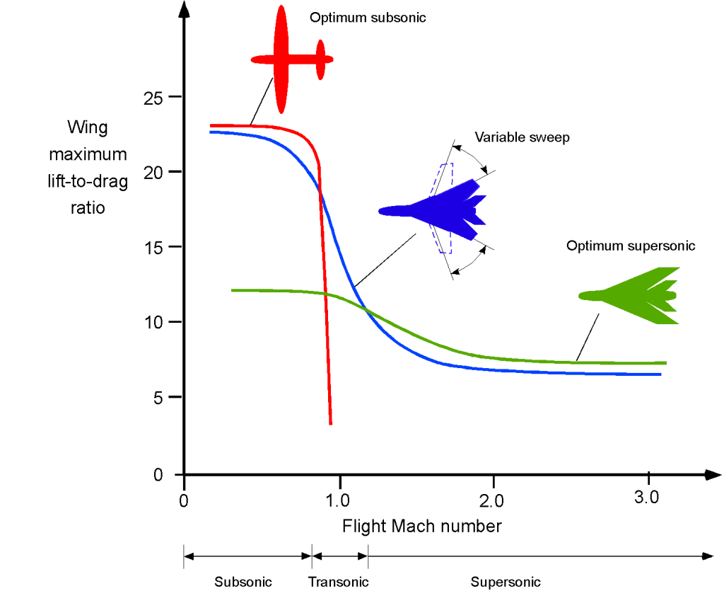
Therefore, there must be trades and design compromises when selecting the sweep angle of an airplane wing. The moderately swept-back cantilever wing with high-lift devices is optimal for flying at Mach 0.8, while the delta wing is best for flight at Mach 2. Delta wings, in particular, are well-suited for continuous supersonic flight. A highly swept wing with a completely subsonic leading edge will perform very well at supersonic speeds and low lift coefficient, but at the cost of poorer low-speed performance, i.e., higher induced drag because of its low aspect ratio wing. A swept wing produces less lift than an equivalent unswept wing, resulting in a higher stall speed and also less maneuver capability because of the lower stall margin. This is why some airplanes, including the B-1 bomber, the F-14, and Tornado fighters, use variable-sweep wings to merge the benefits of unswept and swept wings over the full Mach number envelope of the airplane. However, this aerodynamic advantage comes at the price of structural complexity and weight, amongst other issues.
Supersonic Delta Wings
For sustained supersonic flight, it is known that a delta or triangular wing is close to the optimal type of supersonic wing planform, first theoretically defined by R. T. Jones. It has since been confirmed using wind tunnel and flight test measurements. The advantage of a delta wing is that it can have a larger sweep angle and a greater wing area than a wing just swept back. However, it has also been found that other wing platforms can provide similar aerodynamic benefits, such as low wave drag, in supersonic flight.
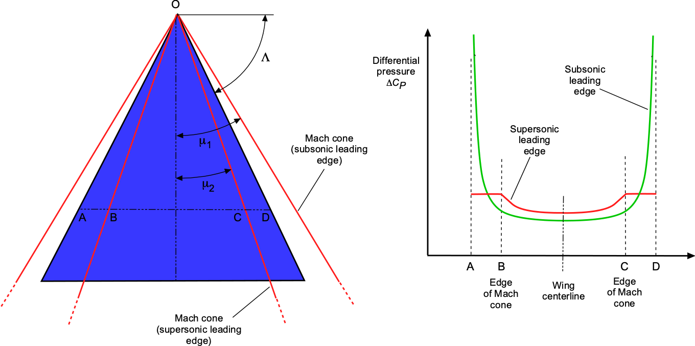
For a delta wing, the flow is conical from the apex of the wing at O, as shown in the figure below. The pressure is constant along any radius vector from O. Two cases must be considered:
- Subsonic leading edge.
- Supersonic leading edge.
With the subsonic leading edge then  . In this case, as shown by the figure, there is a low leading edge pressure (suction) over AB and CD, but the average pressures are less than those for a two-dimensional wing with no sweep. With a supersonic leading edge, then . It is found that the average pressures across AB and CD equal that for a two-dimensional wing with no sweep.
Lift & Drag of Supersonic Delta Wings
The key factors affecting the lift on a supersonic wing are its angle of attack, , operating lift coefficient,  , the freestream (flight) Mach number, , and the wing’s leading edge sweep angle, . For a delta wing, the wave drag is strongly influenced by the leading edge sweep angle, . When the leading edge is subsonic, the effective sweep angle is greater than the Mach angle, which reduces the strength of shock waves and, consequently, the wave drag. A supersonic leading edge creates stronger shock waves on the wings, increasing drag and influencing the lift characteristics. In contrast, a subsonic leading edge allows for smoother airflow and less pronounced shock effects, leading to different lift and drag characteristics as functions of angles of attack and Mach number.
Supersonic Leading Edge
For a thin delta wing with a supersonic leading edge, then  . The lift coefficient can be approximated by
(26) 
where is the angle of attack (in radians), and is the Mach number of the freestream. This result has an underlying, but not unreasonable, two-dimensional assumption that each wing section operates at the same local lift coefficient.
The corresponding drag on a delta wing comprises three main components. The contributions differ based on whether the leading edge is supersonic or subsonic. For a delta wing with a supersonic leading edge, the sources of drag are:
- Wave drag is the dominant source of drag because of the creation of relatively strong shock waves.
- Induced drag, or “drag due to lift,” arises from the effects of the wing tip vortices.
- Skin friction or boundary layer shear stress drag.
The wave drag coefficient,  , can be approximated by
(27) 
Corrections to the wave drag can be applied for wing thickness in the same manner as two-dimensional airfoils.
The induced drag for a delta wing can be more complex to characterize than that of a high aspect ratio wing. For a thin delta wing, the induced drag coefficient,  , is often expressed as
(28) 
where  is the wing’s aspect ratio, and
  is Oswald’s efficiency factor. As airspeed,
  , and flight Mach number increase, the lift coefficient for a given airplane weight,
  , will decrease with the inverse square of the airspeed, i.e.,
(29) 
where  is the reference wing area and
  is the ambient air density. Therefore, the induced drag becomes an increasingly smaller fraction of the total drag. For supersonic flight, the induced drag is typically relatively low because of the low lift coefficients on the wing.
The boundary layer or viscous shear drag,  , on a supersonic wing can be approximated by considering the skin friction coefficient,
  , and the wetted area,
  , of the wing, i.e.,
(30) 
so that  is given by
(31) 
where is the standard wing reference area. Here, is influenced by the Mach number and Reynolds number. For a turbulent boundary layer, can be estimated using empirical correlations such as
(32) 
where the Reynolds number is based on the wing chord. For supersonic flows, modifications to account for compressibility effects are needed, such as using the van Driest transformation, i.e.,
(33) 
The viscous shear drag on a supersonic wing tends to be lower in terms of the skin friction coefficient compared to subsonic conditions. Still, the overall drag is influenced by higher dynamic pressure and complex interactions between shock waves and boundary layers.
The total drag coefficient,  , is then the sum of the wave drag, , induced drag, , and skin friction drag, , i.e.,
(34) 
Subsonic Leading Edge
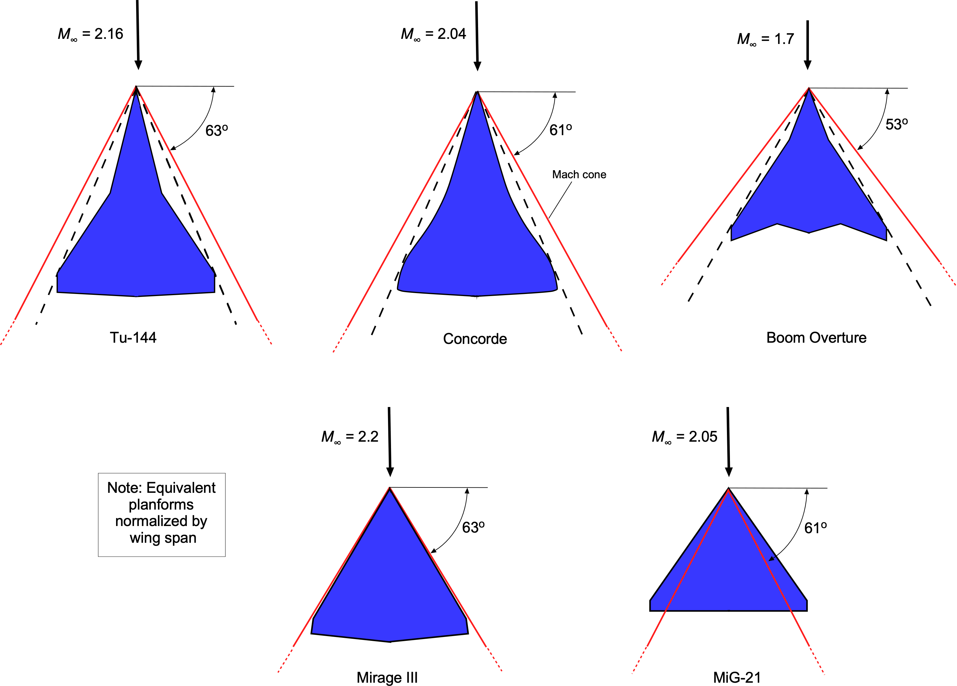
A subsonic leading edge is an ideal operating condition for a supersonic wing, i.e., the leading edge of the wing is swept back behind the Mach cone, i.e., for a subsonic leading edge, then  . As shown in the figure below, the geometric goal for a supersonic airplane at a given design flight Mach number is to sweep the leading edge back behind the Mach cone just enough, with some margin, to ensure it always has a subsonic leading edge. The design should avoid excessive sweep to maintain the wing’s lifting area and aspect ratio. In this regard, the supersonic planforms shown in the figure below all seem just about right.[8] The idea of using a larger sweep angle near the root of the wing is to account for the slightly higher Mach numbers caused by wing/fuselage interference.
For a delta wing with a subsonic leading edge, the lift coefficient can be approximated using linear theory as
(35) 
Given that  for small angles of attack, then
(36) 
For a delta wing with a subsonic leading edge, the wave drag is still present but reduced in intensity. The reduction in wave drag can be attributed to the lower Mach number at which the leading edge operates. When the leading edge is subsonic, the flow around the wing is more streamlined, and the shock waves that form are weaker, resulting in less intense wave drag.
Mathematically, the wave drag coefficient, , for a subsonic leading edge can be expressed as a function of the Mach number and the sweep angle, i.e.,
(37) 
where  (>1) is an empirical factor that accounts for nonlinear effects, viscous effects, and shock wave interactions that are outside the framework of linearized aerodynamic theory; typically, is between 1.2 and 1.4.
The total drag coefficient, , is then the sum of the wave drag, induced drag, and skin friction drag,  , i.e.,
(38) 
Again, the induced drag is typically relatively low because of the low lift coefficients on the wing at supersonic flight speeds.
Supersonic Boundary Layer Characteristics
The viscous shear drag considerations mentioned earlier apply generally to supersonic wings but require further specification depending on whether the leading edge is subsonic or supersonic. When the leading edge is subsonic, the flow remains attached and behaves similarly to subsonic flow around it. The boundary layer begins forming smoothly from the stagnation point, and the primary concern is the development of the boundary layer along the wing’s chord. In this case, the flow over the leading edge does not generate strong shock waves, and the skin friction drag behaves similarly to high-speed subsonic flows, with compressibility effects accounted for.
For a supersonic leading edge, the flow encounters a shock wave at the stagnation line. This introduces a strong shock-boundary layer interaction, which can significantly affect the viscous shear drag. The boundary layer becomes more prone to thickening and separation because of the adverse pressure gradients created by the shock wave. In addition, the shock can trigger an early transition to turbulence immediately downstream of the leading edge, further increasing the skin friction drag.
Delta Wings in the Transonic Regime
All wings, including delta wings, exhibit unique aerodynamic characteristics because shock waves form when transitioning through the transonic regime. This regime is typically defined for a supersonic-capable wing by flight Mach numbers from approximately 0.9 to 1.1, as shown in the figure below. These shock waves create wave drag and can also cause flow separation near the wing’s trailing edge, further increasing drag and reducing lift. The lift generated by delta wings in the transonic regime is influenced by the angle of attack and the strength and positions of the shock waves. It is undesirable to continuously operate a supersonic wing (or aircraft) in this transonic regime, not just because of the high drag but also because of the buffeting caused by shock wave boundary layer interactions and trailing edge flow separation.
The increase in drag and the commensurate increase in thrust required for flight led to this transonic flight regime being called the “sound barrier.” While there is no intrinsic aerodynamic barrier to flight at supersonic speeds, the significant increase in thrust required for an airplane to transition into supersonic flight usually requires an afterburner. After that, the drag coefficient (but not the drag!) diminishes somewhat, and supersonic flight can continue without the afterburner. The overall trend of the aerodynamic characteristics in the subsonic and the supersonic flow just before and just after the transonic regime is that is proportional to  before, and is proportional to
  thereafter.
While cruising at Mach 2, the Concorde could operate without afterburners because the engines and their air inlets were optimized for sustained supersonic flight. However, using the afterburners was essential to overcome the increased drag in the transonic regime. Furthermore, the center of pressure shifts from near the 1/4-chord to near the 1/2-chord as the wing moves through the transonic regime, affecting the airplane’s stability and control. These effects are often mitigated on supersonic airplanes by rebalancing the fuel weight, as was done on the Concorde, or by using an “all-flying” foreplane canard.
The transonic region is generally considered a transitional flight regime because of its inherently low aerodynamic performance and potential issues with stability and control. Supersonic airplanes are designed to pass through this regime quickly when accelerating from subsonic to supersonic speeds or decelerating in the opposite direction, minimizing the time spent in this complex and unfavorable aerodynamic condition.
Other Variations of the Delta Wing
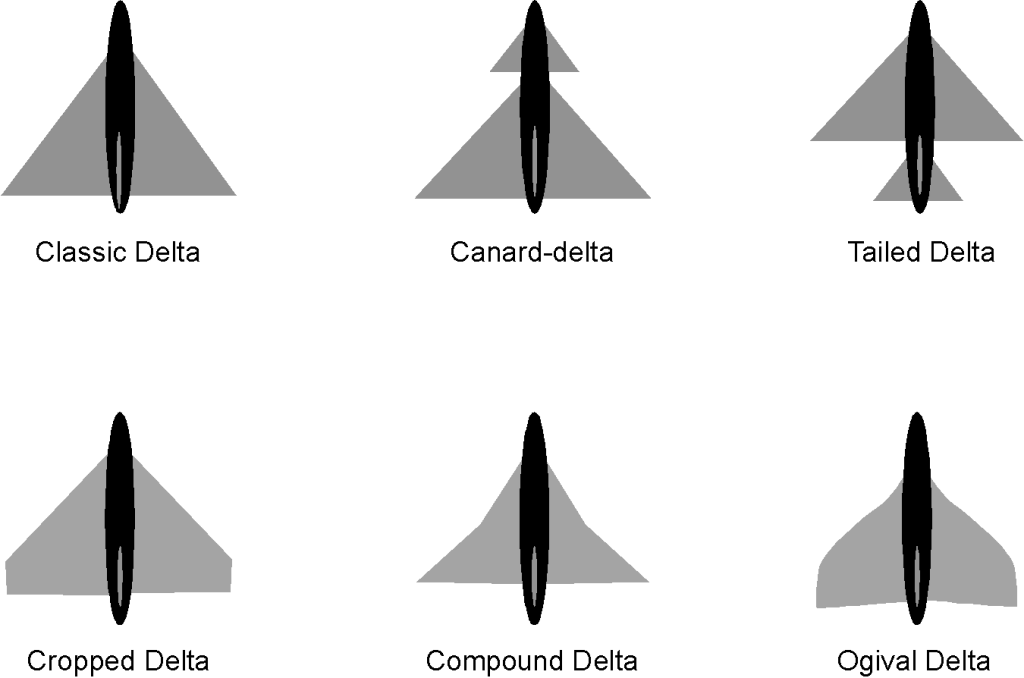
Many variations of the delta wing design have since emerged in the evolution of more efficient supersonic airplanes, as shown in the figure below. The tailless delta wing is the classic design, although experience has shown it could be improved in terms of flight handling qualities. To this end, tailed delta wings have improved the airplane’s pitch control and overall handling qualities, especially when transitioning to and from supersonic flight. In addition, compound and ogival delta wings have been found to have better low-speed and high-angle-of-attack characteristics while still having all of the advantages of supersonic flight.
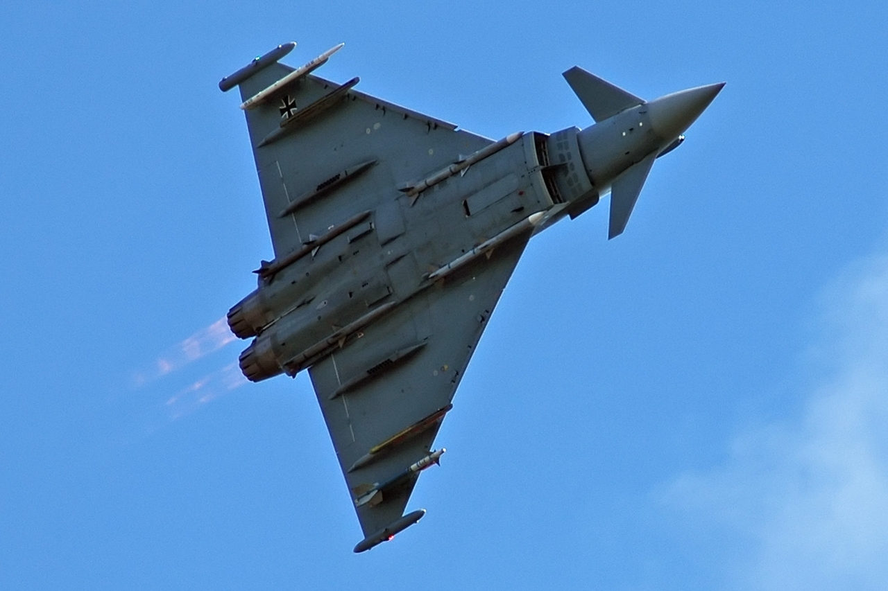
The closely-coupled canard delta configuration is popular because it gives better overall flight characteristics and handling qualities for both supersonic and subsonic flight. The design of supersonic fighter airplanes, including the Eurofighter Typhoon, has become standard, as shown in the photograph below. This closely coupled configuration has a smaller “all-flying” delta fore-plane or canard in front of and above the main delta wing. This canard delta configuration beneficially modifies the airflow over the wing at high angles of attack, keeping it more attached and giving the airplane lower landing speeds and better handling qualities. The all-flying delta-shaped foreplane also gives significant pitching moment authority for control, trim, and maneuverability.
Several other issues have emerged when using pure delta-wing airplanes, including:
1. Controlling the significant changes in pitching moments on the airplane, relative to its center of gravity as it transitions to and from supersonic flight, is difficult to achieve with the normal use of the flight controls on the wing.
2. Concerns about the airplane’s low-speed flight characteristics, the thin wings being prone to stall at low angles of attack, and a susceptibility to developing a behavior known as wing rock. Therefore, the early delta-wing airplanes had high landing speeds, raising many operational challenges.
3. Because relatively thin wings were needed for aerodynamic reasons, it was challenging to obtain the required structural strength and stiffness while ensuring the wing was free from aeroelastic twisting and flutter issues.
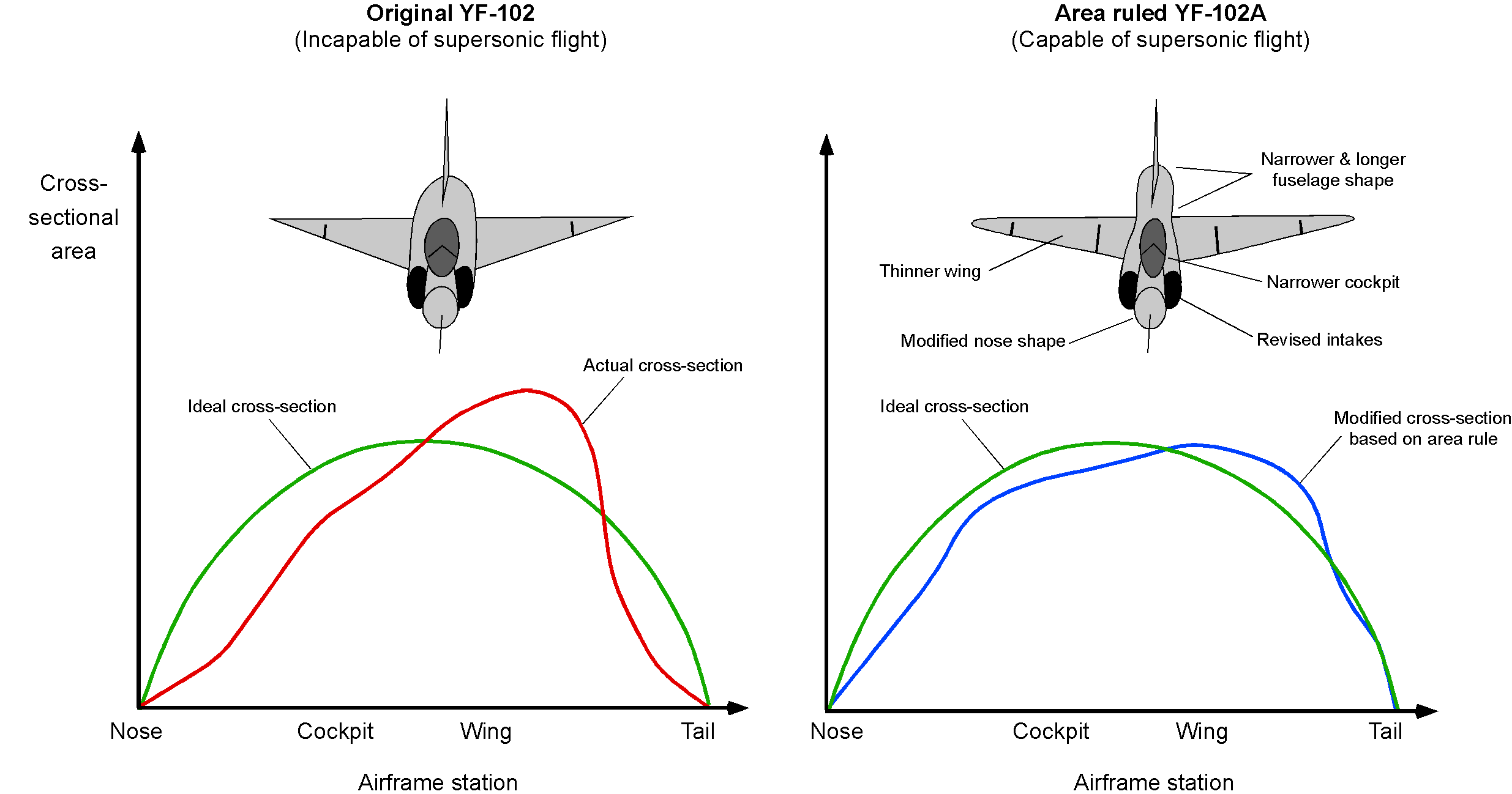
With a delta wing or one of its variants, the supersonic wave drag may be minimized further by employing Whitcomb’s Area Rule along the length of a slender fuselage. This rule can also be used to improve the spanwise lift distribution over the wing as it passes the fuselage; Dietrich Küchemann had originally hypothesized these ideas during WWII. The subtle use of the Area Rule is often noted when examining the fuselage shapes of supersonic fighter airplanes, which may have carefully contoured fuselage shapes to give smooth variations in the cross-sectional shape of the airplane. This rule is tantamount to stating that the rate of change of cross-sectional area with respect to distance measured from the nose should be as gradual as possible. A significant constraint in this aerodynamic shaping process for a fighter is engine integration because the fuselage must contain the engine, the afterburner, and all the engine-associated systems.
Variable Sweep Supersonic Wing Designs
To widen an airplane’s flight envelope, designers strive to meld the benefits of different airplane shapes that perform well in various flight regimes. For example, combining the benefits of efficient subsonic and supersonic flight is desirable. As shown below, these benefits can be accomplished using a variable-sweep or “swing-wing” design. However, it is not always a possible engineering solution, partly because of the extra mechanical complexity and the significant weight penalty.

There can be several missions where a supersonic capability combined with good subsonic efficiency is a highly desirable characteristic. For example, a mission may require an efficient subsonic cruise over large distances to conserve fuel, followed by a shorter supersonic flight to the target, and then a subsonic cruise to return to base. The variable sweep or “swing-wing” design can also better maintain trim as the center of lift on the wing changes from subsonic to supersonic flight and back again, and there is also a center of gravity movement. On the F-14, F-111, and B-1 supersonic bombers, the wings are swept forward for takeoff and landing, significantly reducing the stall speed and improving the low-speed handling qualities.
The lift-to-drag ratio of the F-111 airplane for both subsonic and supersonic flight is shown in the figure below. Notice the improvement in the lift-to-drag ratio as the wings are swept forward, which is an expected behavior based on the corresponding increase in wing aspect ratio. A lift-to-drag ratio between 4 and 5 in supersonic flight is typical for any swept delta-wing airplane.
One disadvantage of a swing-wing airplane is the added structural weight and mechanical complexity associated with the sweep pivot joint and its actuator mechanisms. Additionally, variable-geometry wings are more difficult to design with low radar cross-section characteristics, which poses a significant challenge for military applications.
Examining any military fighter airplane will show that the wing pylons are generally always needed to carry bombs, air-launched weapons, and long-range fuel tanks. Therefore, another disadvantage of a variable-sweep wing is that pylon stations on the wing’s outer (swing) part are only possible if they can be mechanically designed to be reoriented to point into the relative flow. Pivoting pylons have been used on some airplanes with variable geometry. While they incur a weight penalty, they can significantly enhance the airplane’s capabilities, in that it can now carry weapons or external fuel tanks.
Pivoting wing pylon systems for external stores and weapons carriage have been used on the General Dynamics F-111 and the Panavia Tornado to keep them facing into the flow as the wing sweeps backward and forward. Mechanically, this can be done using a form of pantograph, with one end fixed to the fuselage and the other to the pylon. The F-111’s outermost pair of pylons did not swivel and were only used when the wing was fully swept forward, limiting the airplane to subsonic flight with fuel tanks, such as for long-range ferry flights.
Engines for Supersonic Flight
A turbojet engine is suitable for use in supersonic flight. The thrust from a turbojet engine increases approximately linearly with the supersonic flight Mach number, primarily because of the increased mass flow rate through the engine at higher speeds. This behavior appears favorable for supersonic propulsion: the faster the aircraft flies, the more air it captures, and the more thrust the engine can potentially generate. However, this trend holds only within a limited Mach number range. In reality, several aerodynamic and thermodynamic constraints begin to emerge at higher Mach numbers, which complicate and eventually limit thrust production.
One critical factor is the need to decelerate the incoming supersonic air to subsonic speeds before it enters the engine’s compressor. Compressors are not designed to handle supersonic inflow; doing so would cause shock formation, severe flow separation, pressure losses, and potential compressor stall. To avoid this, the inlet system must include a series of shock waves and compression surfaces to slow and compress the flow in a controlled manner. While this process recovers some of the kinetic energy as pressure, it also introduces total pressure losses and thermal loading.
Additionally, as the Mach number increases, stagnation temperatures rise sharply, pushing materials and cooling systems to their thermal limits. Furthermore, drag increases with Mach number, meaning that the net propulsive efficiency may decrease even as engine thrust increases. Therefore, while turbojets can operate effectively into the low supersonic regime, their performance becomes increasingly constrained at higher Mach numbers, motivating the development of specialized configurations such as ramjets and scramjets for high-speed flight.
Inlet Conditions
As the freestream Mach number increases beyond unity, the incoming air must be decelerated to subsonic speeds before entering the compressor stage of a turbojet engine, because of the aerodynamic and mechanical limitations of axial compressors. In supersonic flight, this requirement imposes strict demands on the inlet system, which must be carefully designed to manage the location and strength of shock waves and minimize the possibility of strong shock wave/boundary layer interactions. The idea is to use a suitable inlet to reduce the flow speeds to subsonic conditions at the face of the compressor, while maintaining as much total pressure as possible, i.e., by minimizing all sources of losses.
For a supersonic-capable turbojet, this goal is typically accomplished by using a fixed or variable-geometry duct equipped with conical spikes, ramps, doors, or baffles, which control the flow within the inlet upstream of the engine. For example, on the SR-71, the engines were equipped with a variable-geometry spike inlet and bypass system. As the aircraft accelerated, the conical spike was gradually retracted to control the engine’s inlet conditions. Newer concepts such as the diverterless supersonic inlet (DSI) aim to simplify the design by eliminating diverters. While DSIs offer advantages in reduced weight, mechanical complexity, and radar signature, they are typically optimized for a narrow Mach range. They must be carefully matched to the engine and flight profile to ensure stable operation across the envelope.
The figure below shows an example of the system used on the Rolls-Royce/Snecma Olympus 593 turbojet engines that were used to power the Concorde SST. Its variable-geometry inlet system employed a movable intake ramp and spill doors to manage the shock wave structures and airflow across its flight envelope. This arrangement enabled precise control over the positions of intake shock waves, thereby maintaining high values of pressure recovery and stable engine operations at supersonic cruise. At takeoff and during subsonic acceleration, the intake ramps were fully retracted (lifted up) to maximize the intake area and deliver the maximum possible mass flow into the engines. The auxiliary inlet doors were fully open, allowing additional air into the engine intake, while the downstream door admitted bypass air for engine cooling.
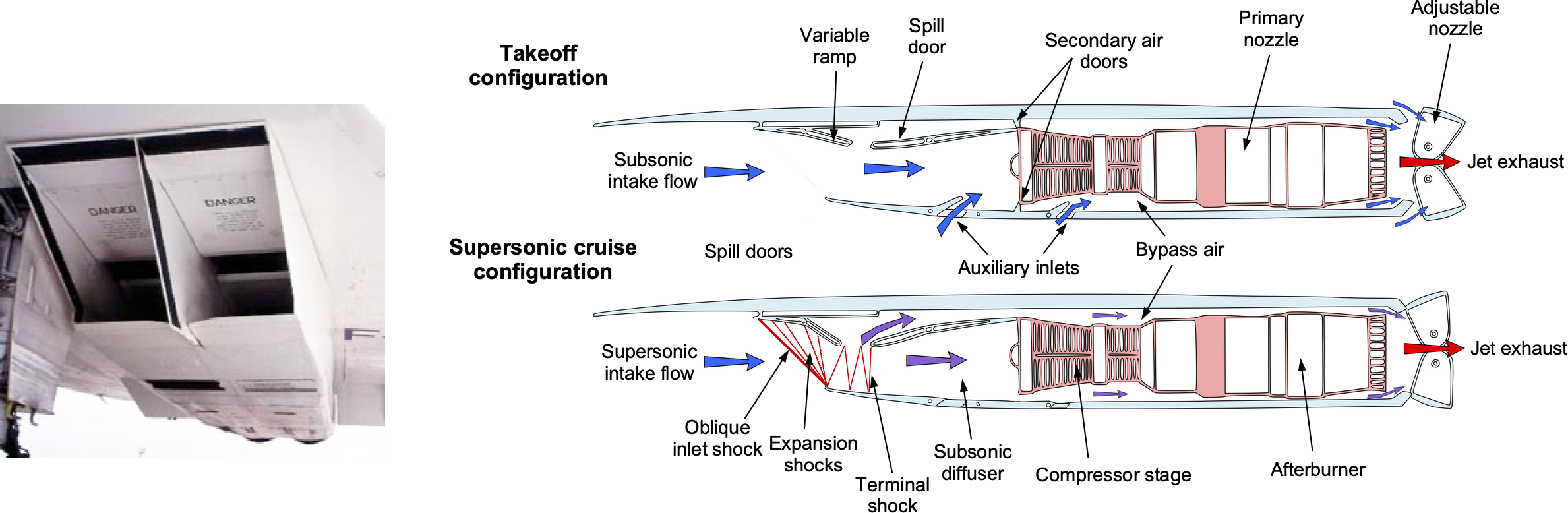
A turbojet engine cannot realize its maximum performance potential in supersonic cruise without effective pressure recovery. Therefore, as the Concorde accelerated, the intake ramps were moved downward to keep the engine inlet conditions subsonic. At cruise, near Mach 2.0, the intake ramps were fully deployed to generate external oblique shock waves that decelerated the flow to about Mach 1.5. A terminal shock wave was formed at the throat of the diffuser, bringing the flow to subsonic conditions. The increasing area of the diffuser further slowed the flow and raised the static pressure before it reached the engine intake. Spill doors vented any excess air during throttle transients to maintain the stability of the intake flow. Ramp angles and spill door positions were pre-programmed based on Mach number using a digital control system to hold the terminal shock near the throat. Therefore, the engine received a continuous, steady, subsonic, high-pressure airflow, ensuring a stable and efficient cruise performance. On Concorde, it is noteworthy that the close-to-ideal conditions produced by the variable-geometry inlets contributed to over 60% of the total propulsive force at Mach 2.
Thrust Production
The net thrust from a turbojet engine is governed by a momentum balance across its control volume. For steady flow with negligible pressure thrust (e.g., an ideally expanded nozzle), the thrust is given by
(39) 
where  and
and  are the exhaust mass flow rate and jet velocity, respectively, and
  and refer to the freestream conditions. If the fuel mass flow is negligible relative to the incoming air, so that
  , this latter result simplifies to
(40) 
Notice that supersonic engines use variable-geometry convergent-divergent nozzles to ensure ideal engine flow expansion. For example, Concorde employed a nozzle that was continuously adjusted during flight. By matching the nozzle exit pressure to the ambient pressure, especially at higher altitudes, the system minimized thrust losses and improved the engine’s overall propulsive efficiency.
The engine mass flow rate is approximately
(41) 
assuming ideal gas behavior and a fixed inlet area,  . As Mach number increases, both
  and increase, causing the thrust to rise almost linearly with , though this trend is offset by the reduction in air density at higher altitude, as illustrated in the figure below.
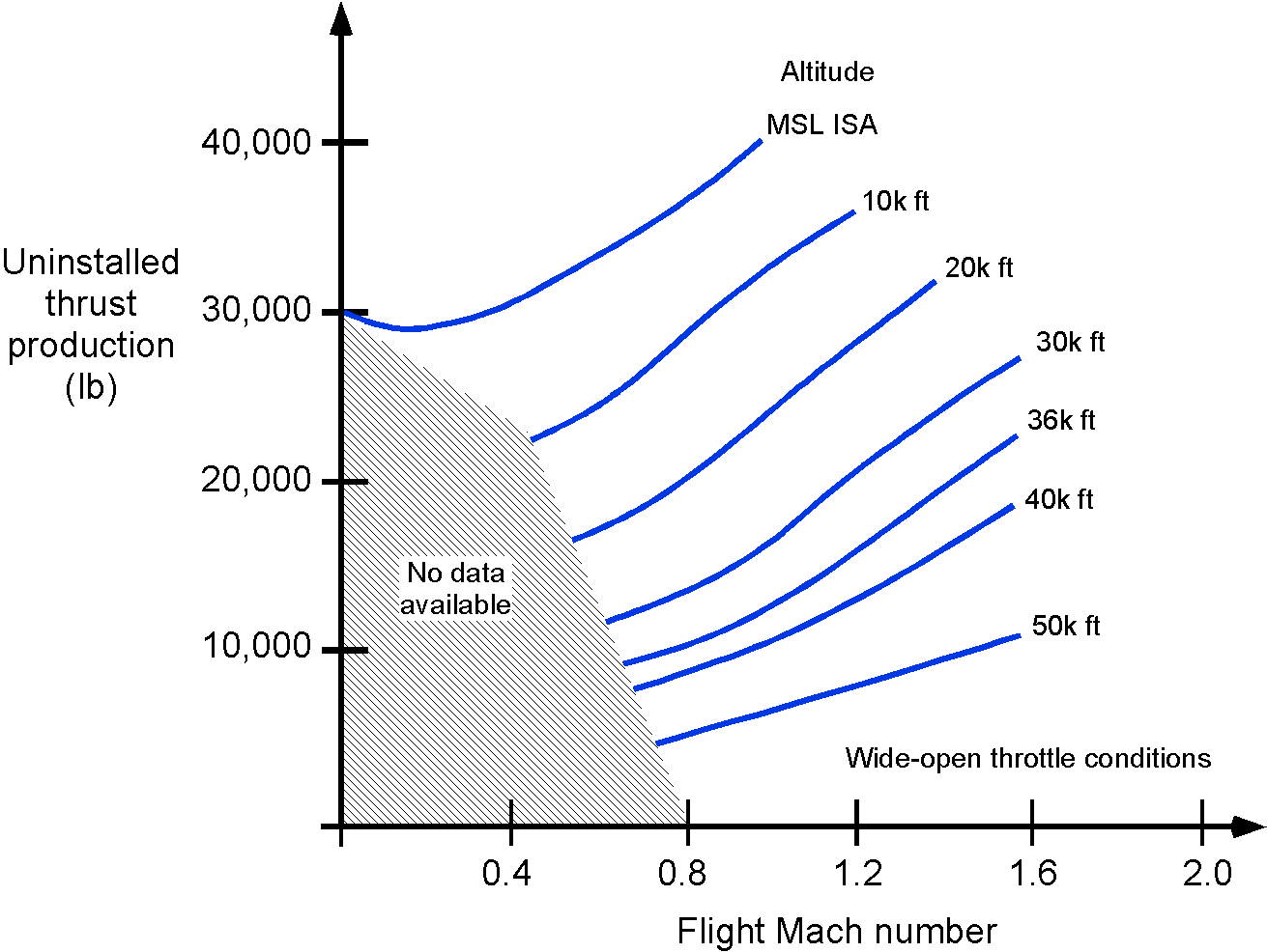
The ability to produce a high exhaust jet velocity with a turbojet depends on the stagnation conditions available at the engine intake. In supersonic flight, the inlet must decelerate and compress the freestream flow. As previously explained, this goal is achieved using shock waves and duct geometry, which raise the pressure and temperature but also incur some losses. These losses can be represented by the inlet pressure recovery ratio  , defined as the ratio of stagnation pressure at the engine intake,
  , to the freestream stagnation pressure,
  , i.e.,
(42) 
The resulting pressure loss will limit the maximum pressure available to support combustion in the engine core, thereby limiting the exhaust velocity, . Assuming isentropic flow through a choked nozzle from the turbine exit, the exhaust velocity can be estimated from the energy equation as
(43) 
where is the specific heat at constant pressure,  is the combustor entry temperature ratio, and
  is the compressor temperature ratio. At higher Mach numbers, decreases in value because of increasing shock wave and boundary layer thickening losses. Meanwhile, the total temperature of the freestream increases according to
(44) 
which raises the inlet temperature. However, because of turbine material constraints, this increase limits the allowable temperature rise during combustion. Therefore, even though the incoming total energy increases, the usable thermal drop across the turbine and nozzle constrains engine operation.
Therefore, it becomes clear that intake design is critical for delivering mass flow and pressure to the engine and producing thrust. On Concorde, the variable-geometry inlets achieved a pressure recovery ratio of approximately  at Mach 2. This enabled the engine to operate with greater efficiency and higher net thrust; the inlet alone contributed over 60% of the total propulsive force at cruise.
TSFC Characteristics
Efficient pressure recovery is, therefore, essential to realizing the performance potential of supersonic turbojet propulsion. The highest inlet pressure recovery is also critical because inlet losses dominate the TSFC in supersonic cruise. Representative variations of the TSFC of a turbojet engine in supersonic flow are shown in the figure below. The thrust-specific fuel consumption (TSFC), defined as
(45) 
Notice that the TSFC of a turbojet engine generally gets worse (i.e., increases) with increasing flight Mach number into the supersonic regime. Even though the intake pressure increases with Mach number and thrust production, the fuel flow rate increases faster, causing propulsive efficiency to drop and leading to a higher TSFC.
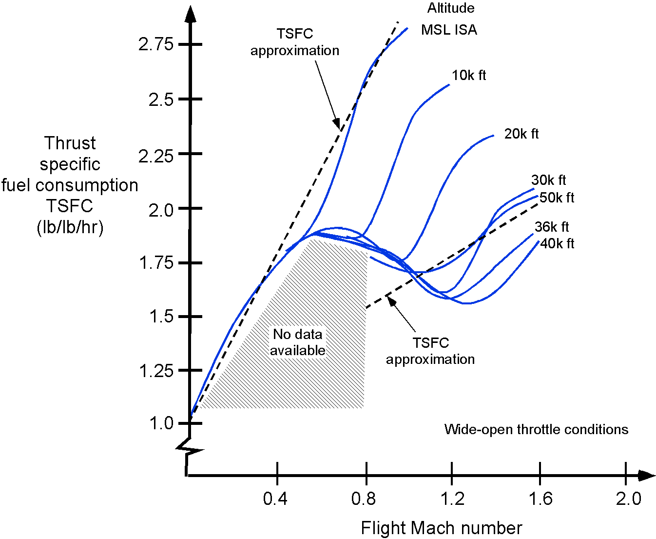
While most supersonic airplanes have used afterburners to boost thrust, especially during the transonic regime, this comes at the cost of a sharp increase in thrust-specific fuel consumption (TSFC). The afterburner works by injecting additional fuel downstream of the turbine to reheat the exhaust gases before expansion in the nozzle, thereby increasing jet velocity and augmenting thrust. However, this process is thermodynamically inefficient, and the fuel flow rate rises rapidly, making sustained supersonic cruise with afterburner operation extremely fuel-inefficient. The Tupolev Tu-144, for example, required continuous afterburner use to maintain supersonic flight, unlike Concorde, whose engines could produce sufficient thrust without afterburners during cruise.
To improve overall performance and reduce TSFC, a supersonic airplane can use low-bypass turbofans instead of pure turbojets. These engines incorporate a bypass stream that increases the total mass flow through the propulsion system without giving a proportional increase in core temperature. The bypass stream produces thrust at a lower exhaust velocity, improving the engine’s overall propulsive efficiency, which is defined as
(46) 
This ratio becomes more favorable when is closer to , as in the case of a turbofan. Although the bypass ratio must remain low to avoid aerodynamic drag from the engine installation at supersonic speeds, even a modest bypass stream can provide significant benefits regarding reduced TSFC and overall thrust performance.
Design & Integration Challenges
Maintaining efficient supersonic cruise, especially over long ranges, is one of the most formidable challenges in aircraft design. It requires more than simply generating high thrust; achieving this performance depends on minimizing wave drag, which increases rapidly with Mach number and is highly sensitive to even minor geometric deviations. Consequently, the airframe must be precisely shaped, with long, slender fuselages, smoothly contoured surfaces, and thin wings with short spans and highly swept leading edges to reduce both drag and structural weight.
In addition, the propulsion system cannot be treated in isolation. Inlet geometry, nozzle configuration, and thermal management must all be carefully integrated with the airframe to ensure stable engine operation, good pressure recovery, and efficient thrust across the flight envelope. Thrust-specific fuel consumption (TSFC) also becomes a critical factor, as high fuel burn at supersonic speeds can severely limit range unless the propulsion system is optimized for cruise efficiency. Sustained supersonic cruise is not merely an extension of subsonic design practices. It is a fundamentally different and more exacting design problem that requires close coordination across structures, aerodynamics, propulsion, and systems.
Supersonic Transport (SST) Airplanes
There was much interest in developing supersonic transport (SST) airplanes during the 1960s, with significant technical efforts being led by the British and French airplane industries. The Anglo-French Concorde became the World’s first SST, which flew first in 1969 and went into operational service in 1976. The Concorde used a tailless ogival-shaped “slender-delta” wing, carefully designed and integrated with the propulsion system to give good lift-to-drag in supersonic flight but also acceptable low-speed flight characteristics for takeoff and landing. However, a big issue for the Concorde was the intensity of its “sonic boom,” which limited its routes mostly over the North Atlantic between New York and London.
The Russians developed the Tupolev Tu-144, which resembled the Concorde but was distinctive in its use of retractable foreplane canards. Both the Concorde and Tu-144 were designed for cruising at just over Mach 2 at 60,000 feet, which was the highest Mach number that could be obtained without excessive kinetic heating of the airframe. Consequently, the Concorde and the Tu-144 had to use special high-temperature aluminum alloys in their construction and various other design features to allow the airframe to expand during flight. Conventional airplanes use various aluminum alloys, but these materials tend to soften and lose their strength at the temperatures produced by kinetic heating at Mach 2 and above.
Only 14 Concorde SSTs were built, and the airplane was never economically viable for broader airline service except over the North Atlantic. Nevertheless, it was a very popular airplane with both the passengers and the flight crews alike. British Airways and Air France flew the Concorde for over 25 years until it was abruptly retired in 2003 after a crash.[9] With a take-off speed of about 220 knots (250 mph) and a cruising speed of 1,350 mph, which was just a little more than twice the speed of sound, a typical London to New York crossing was accomplished in 3 and 1/2 hours, compared to 8 hours for a subsonic flight. The Concorde holds many aviation records, including the fastest transatlantic airliner flight (New York JFK to London Heathrow) in 2 hours and 53 minutes. However, the Tu-144 was unsuccessful as a commercial airplane. After two crashes, including one on a delivery flight to Aeroflot, it was permanently retired after only 55 passenger flights.
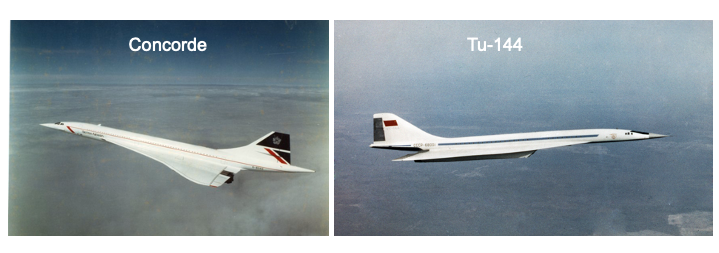
In the 1970s, Boeing planned to develop an SST, initially using a variable geometry or “swing-wing” design, the final evolution of the concept shown in the figure below. The idea of the swing-wing design has already been discussed. For civil airplanes, this design could allow them to fly efficiently at subsonic speeds over land and inside terminal areas while having all the advantages of an efficient supersonic cruise.
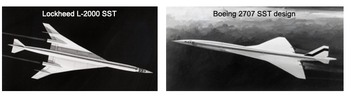
However, despite the potential aerodynamic benefits of a swing-wing concept, Boeing’s detailed engineering analyses proved too challenging from an airframe weight perspective. Boeing’s final 2707 SST concept was a more conventional supersonic delta-shaped wing. The Boeing design was also much larger than the Concorde or the Tu-144 and was intended to cruise at Mach 3 with more passengers. However, the combination of technical problems, high development costs, concerns about the intensity of sonic booms, and the lack of a passenger market for airlines eventually led to its cancellation.
Slender Delta Concept
Like most delta-wing fighter-type airplanes, they do not inherently have good aerodynamic characteristics at low flight speeds and high angles of attack, such as during takeoff and landing. Takeoff and landing speeds are high for such airplanes, requiring long runways. Concorde was specially designed to use a vortex-lift concept to improve the low-speed, high-angle of attack flight. The airplane had no high lift devices, so to reduce the landing speeds, the wing was designed to promote a phenomenon called vortex lift.
In the early 1950s, Weber and Küchemann at the RAE (Royal Aircraft Establishment) in the U.K. published a series of papers on a new type of delta-wing planform known as the “slender delta” concept. If designed appropriately, delta wings could produce robust and stable vortex flows on their upper surfaces at low airspeeds and high angles of attack, as shown in the schematic below. The presence of these vortices creates very low-pressure zones, significantly increasing the lift on the wing. All modern supersonic airplanes are explicitly designed to take advantage of the benefits of vortex lift at low airspeeds.
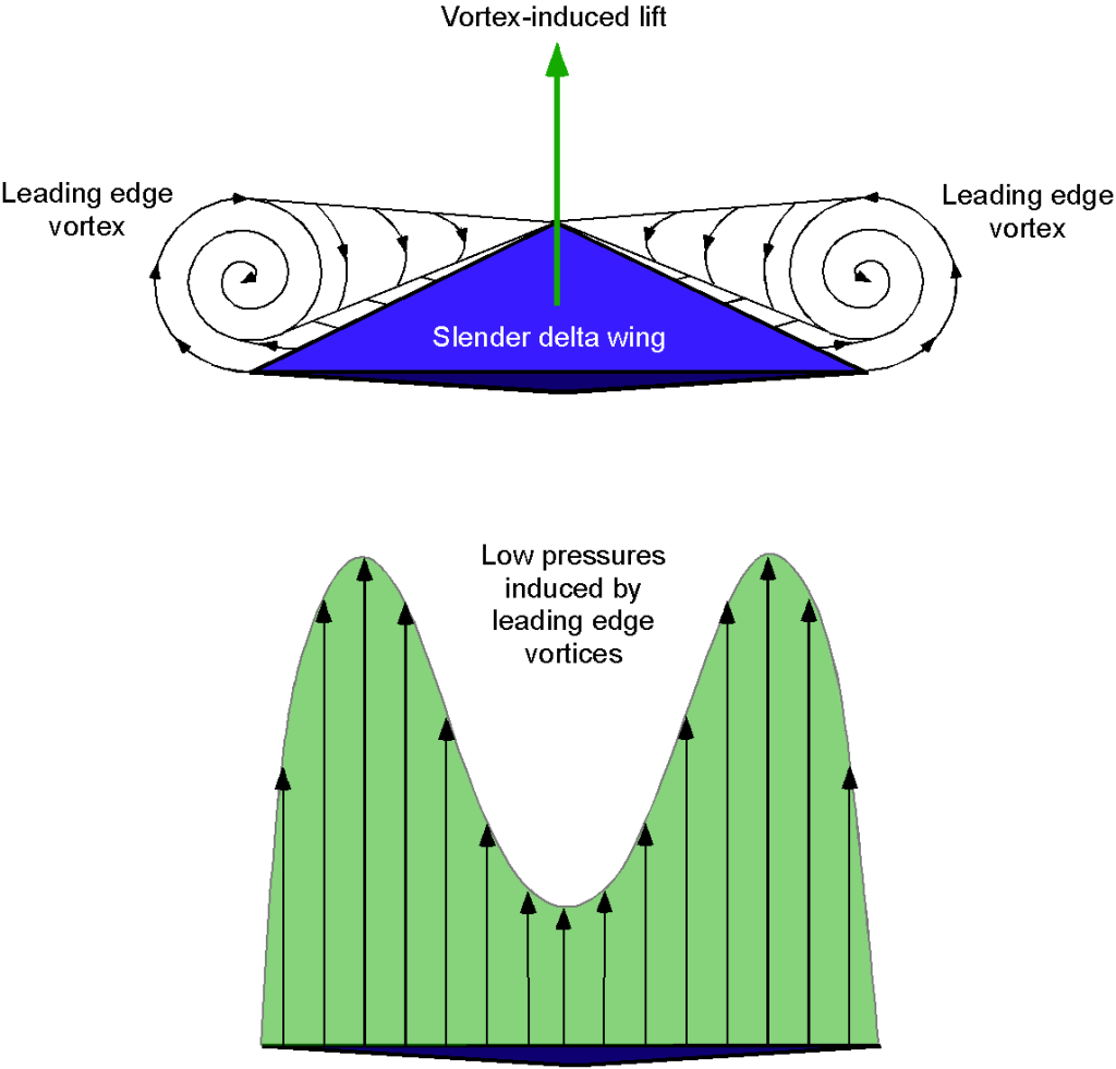
Weber and Küchemann determined that the lift from the leading-edge vortex flows could be maximized by increasing the slenderness of the wing and slightly drooping the leading-edge camber. This approach would retain good supersonic performance while also allowing for high maximum lift at low airspeeds, as shown in the figure below, resulting in much lower takeoff and landing speeds. The unfortunate byproduct is also a significant increase in drag, which requires considerable thrust and power to overcome, even when landing.
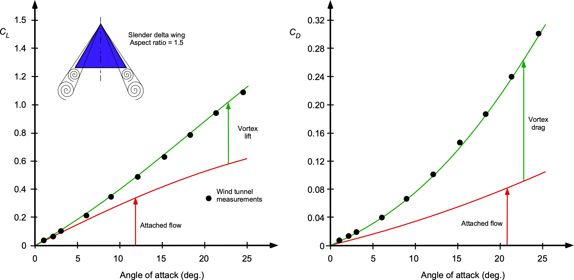
However, Concorde had to be flown at an extremely high angle of attack to achieve this condition, which was a distinctive (if not rather alarming) flight attitude during takeoffs and landings. Indeed, the angle of attack on takeoff and landing was so high that the airplane was designed with a “drooped-nose” feature to allow the pilots to see over the nose of the airplane. Concorde was also distinctive because of its exceptionally tall landing gear, which was needed to enable the airplane to rotate to the required angle of attack for takeoff without the tail striking the runway.
Polhamus developed a practical model[10] to account for the additional lift generated by leading-edge vortices on sharp-edged delta wings at high angles of attack. He proposed an analogy with the leading-edge suction effect observed in attached potential flow over rounded edges. Even though the flow over delta wings is separated, the vortices act as a surrogate for the suction peak, maintaining attached-like lift behavior in a time-averaged sense. The total lift coefficient is modeled as a combination of potential-flow lift and vortex lift, expressed as
(47) 
where  is the angle of attack,
  is the potential flow lift coefficient (geometry-dependent), and
  is the vortex lift coefficient (empirically determined). This model provides a useful semi-empirical prediction of lift for slender wings with sharp leading edges and is especially applicable to delta-wing aircraft operating at high angles of attack. Polhamus later extended the model[11] to estimate induced drag from vortex lift.
Kinetic Heating
A significant challenge for supersonic and hypersonic flight vehicles is the intense aerodynamic heating of the airframe resulting from both air friction and convective heat transfer. This thermal environment posed a significant design constraint for the Concorde. Convective heating refers to the transfer of thermal energy from the air to the vehicle surface, where the kinetic energy of the incoming flow is partially converted into heat as the air decelerates and compresses within the boundary layer. In this region, temperature gradients develop between the hotter, compressed air near the surface and the cooler structure beneath, leading to a continuous influx of heat into the airframe.
At high flight speeds, the convective heat flux to an aircraft surface in compressible flow scales approximately with the cube of the airspeed, i.e., the heat flux,  , varies as
(48) 
where the flow velocity (flight airspeed) is related to the flight Mach number by  , and the local ambient speed of sound is given by
  . Assuming constant ambient density and temperature, the scaling becomes proportional to the cube of flight Mach number, i.e.,
(49) 
Therefore, doubling the Mach number leads to an eightfold increase in kinetic heating.
The consequence of this heating is that the air temperature adjacent to the aircraft’s skin rises significantly above the ambient static temperature. This thermal energy is then transferred into the structure by convection. An estimate of the surface temperature under these conditions can be obtained using the adiabatic wall temperature, representing the upper limit the surface would reach if no heat were lost to conduction or radiation. Assuming a fully turbulent boundary layer, this temperature is given by
(50) 
where is the ambient static temperature, and  for air. This expression provides a practical upper-bound estimate for the wall temperature in supersonic flow and shows that it increases with the square of the flight Mach number. The levels of aerodynamic kinetic heating impose strict thermal requirements on materials and structural design for both supersonic and hypersonic vehicles.
The graphic below illustrates the variation in skin temperature experienced by Concorde during cruise at Mach 2.1 and an altitude of approximately 60,000 feet. At this altitude, the ambient temperature is about -69F (-56C). In contrast, the surface temperature of the aircraft reached approximately 266F (130C) at the nose and about 199F (93C) at the tail. The resulting thermal expansion, compounded by the sustained high-speed flight, caused the fuselage to lengthen by nearly 18 cm (about 7 inches). The airframe incorporated special design features to accommodate this expansion without introducing excessive structural stresses, including expansion joints and flexible mounting structures at critical locations inside the wings and along the fuselage.
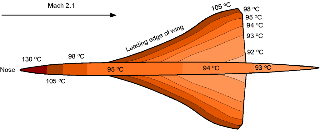
Traditional aluminum alloys cannot tolerate the elevated temperatures encountered in sustained supersonic flight, so specialized materials were required to construct the Concorde. To address this, high-temperature aluminum alloys were employed, most notably Hiduminium RR58, which is a light alloy with significantly greater thermal resistance than conventional aluminum. Hiduminium RR58 was used extensively in the primary structure of the aircraft. Additionally, high-temperature steel and stainless steel honeycomb were used in areas exposed to greater thermal and mechanical loads, while insulated resin-bonded glass fiber composites were applied in the nose region, where the surface temperatures were highest.
Sonic Booms
A significant challenge facing supersonic transport (SST) aircraft and other flight vehicles operating at supersonic or hypersonic speeds is the generation of “sonic booms.” These booms arise from a complex system of shock waves and expansion fans that form around the vehicle, with dominant contributions from a bow shock at the nose and a recompression shock at the tail. Shock waves are extreme pressure disturbances that propagate through the air without much dissipation or reflection. To an observer on the ground below the overflying aircraft, these disturbances arrive as a rapid pressure change in the form of an “N-wave,” usually perceived as an overpressure followed quickly by an underpressure, producing the characteristic “boom-boom” noise, as illustrated in the figure below.
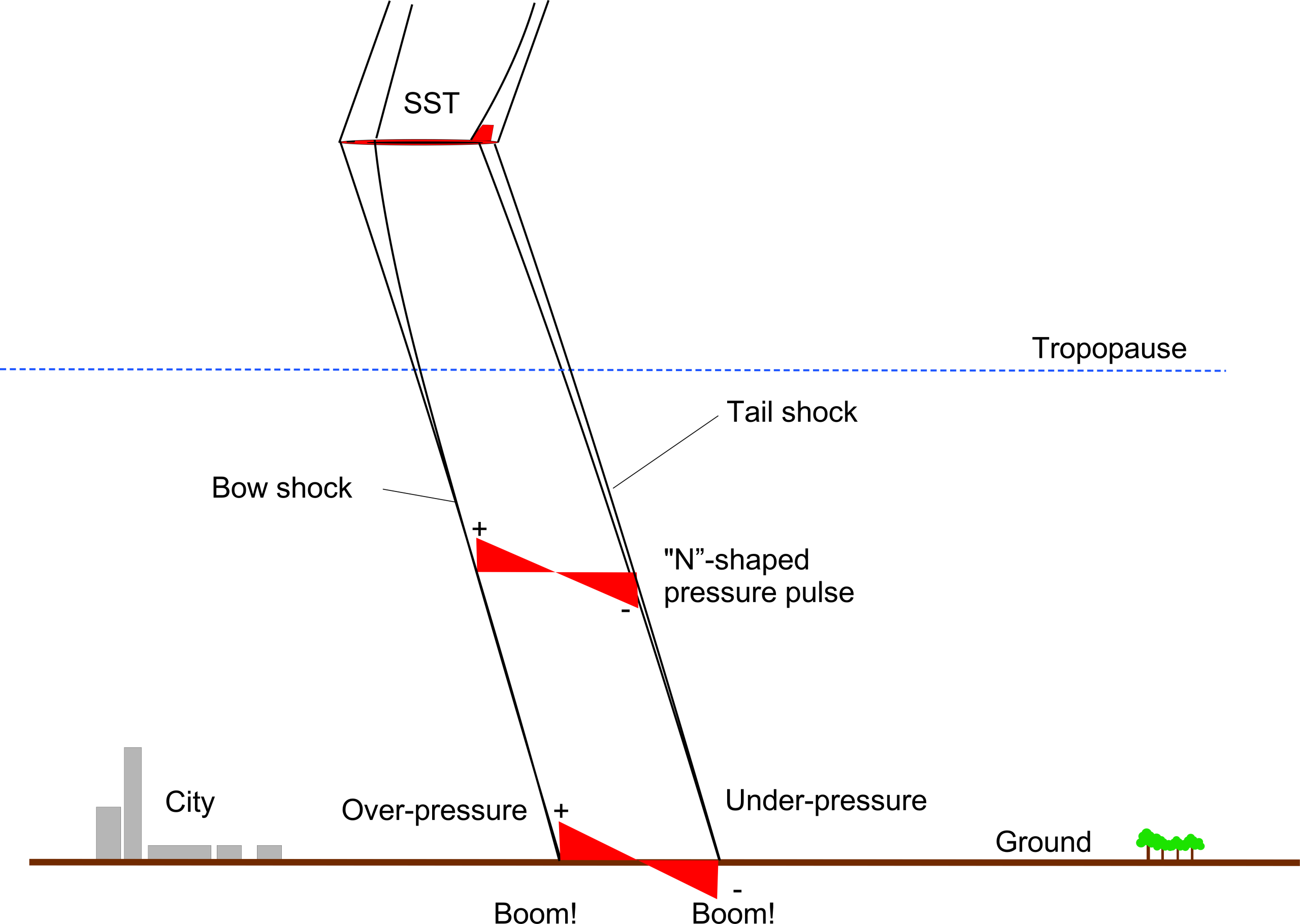
A ground observer often describes a sonic boom as sounding like two sharp cracks, similar to pistol shots, occurring in rapid succession. This phenomenon is not only disruptive but can also be very startling. In the case of Concorde, the sonic boom overpressure produced sound levels exceeding 135 dB, which was strong enough to rattle windows, even many miles away from the flight path. Despite these concerns, research continues into sonic boom mitigation, including reshaping the aircraft’s nose, wings, and fuselage to control the formation and propagation of shock waves and reduce ground-level noise impact. However, it remains to be seen if this problem of sonic booms can be mitigated enough for any future SST to meet noise regulations.
Geometry of Sonic Booms
These shock waves or “sonic booms” do not arrive at the ground uniformly. Instead, they form curved traces, the geometry of which is governed mathematically by the intersection of the Mach cone with the Earth’s surface, as shown in the illustration below. As the aircraft moves faster than the speed of sound, it continuously generates spherical pressure waves that trail behind it. The shock waves that form the boundary of two Mach cones are effectively carried along with the aircraft, extending indefinitely behind it. Recall that the half-angle of this cone, known as the Mach angle, is given by
(51) 
where is the flight Mach number and is the angle between the Mach cone and the flight path.
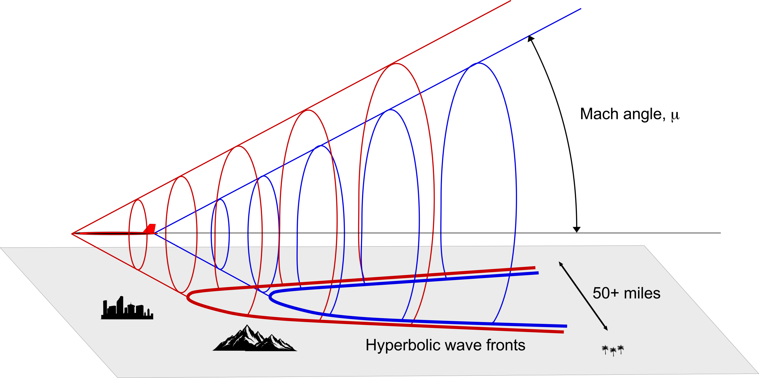
To determine how a Mach cone intersects the ground, consider an aircraft flying supersonically at a constant airspeed of and a constant altitude  . Each pressure disturbance propagates outward at the speed of sound
  . At any time , the wavefront from a source point at
  and
and  expands spherically and satisfies
(52) 
On the ground plane at  , this result becomes
(53) 
which describes a family of expanding circles centered at the instantaneous position of the aircraft projected to the ground, which is assumed to be flat. However, as time progresses and the aircraft moves forward, the envelope of all these circular intersections traces out a pair of hyperbolic wavefronts on the ground, which can be explained by expressing the ground trace in terms of spatial coordinates. The wavefront satisfies the condition
(54) 
which simplifies to the canonical form of a hyperbola, i.e.,
(55) 
where  , and
, and  is the horizontal position of the aircraft when the shock originated.
Therefore, the compression bow shock and expansion tail shock each form separate Mach cones that intersect the ground in distinct hyperbolic patterns. These wavefronts correspond to the perceived sonic boom from the overflying aircraft as the overpressure and underpressure zones sweep over a ground observer. The spatial separation of the two hyperbolic branches produces the well-known “N-wave” signature, which, as previously explained, consists of a sudden rise in pressure (bow shock), a gradual decay, and then a sharp drop (tail shock). Understanding this wavefront geometry and its extent is crucial for analyzing the impact zone or sonic carpet[12] of sonic booms but also for designing aircraft profiles that can reduce the sharpness or intensity of these wavefronts, thereby mitigating their effects on populated areas.
Sonic Boom Mitigation?
Sonic booms are so intrinsic to supersonic flight that they have been studied by NASA and other organizations for many decades, the research being documented in an excellent review publication. The development of supersonic transport (SST) airplanes such as Concorde and various military flight programs has led to many other publications on sonic booms and the factors that affect them. The principles for sonic boom mitigation seem straightforward, but the theoretical approaches have not yet been demonstrated in flight. In this context, sonic boom mitigation refers to a set of aerodynamic design methods and/or flight operation techniques to reduce the intensity and audibility of sonic booms produced by supersonic aircraft. These strategies can include reshaping the airframe to alter the near-field pressure signature, thereby reducing the strength and abruptness of the pressure wave that reaches the ground. Such efforts are essential for enabling future civil supersonic aircraft to operate without generating objectionable sonic boom footprints.
With renewed interest in SSTs, in 2017, NASA issued a draft request for proposals for developing a Quiet Supersonic Transport (QueSST) low-boom flight demonstrator. This program called for designing and testing a new X-plane to support the development of future-generation SST concepts. The contract was awarded to Lockheed Martin, and its Skunk Works X-59 supersonic demonstrator has been designed with a long, carefully shaped nose, as shown in the artist’s rendering below. The X-59 is expected to cruise at 55,000 feet and Mach 1.4. As of May 2025, the aircraft has not yet flown but has completed key ground testing milestones. In December 2024, NASA successfully conducted a full-power engine test using an afterburner, validating the propulsion system’s readiness for flight. The aircraft’s first flight is now expected later in 2025.
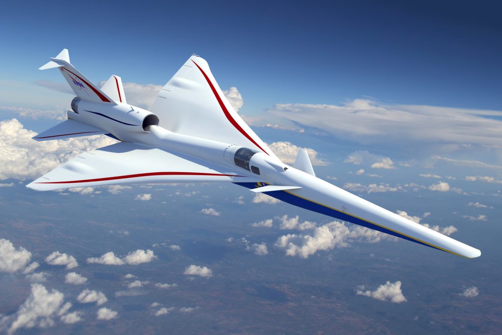
Following initial flight tests, NASA intends to conduct community overflight studies across selected U.S. cities to assess public perception of the aircraft’s (predicted) reduced sonic boom signature, referred to as a “sonic thump,” as further explained in the figure below based on NASA research. Still, unless the reductions in sonic boom intensity are significant, this demonstration will unlikely change the public’s opinion about sonic booms after the psychoacoustic supersonic flight tests conducted over London and Oklahoma City in the 1960s, which were performed at similar flight Mach numbers. Nevertheless, these flight test campaigns may ultimately inform regulatory decisions by the FAA and contribute to the development of international sonic boom standards by ICAO, potentially paving the way for future commercial supersonic flight over land.
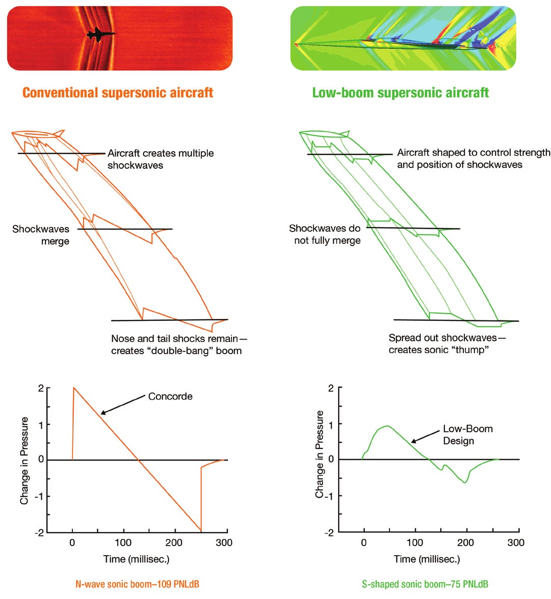
Sonic Boom Intensity
The main challenge in mitigating a sonic boom is that its intensity depends strongly on the aircraft’s weight and flight Mach number. Mach 1.4 is too slow for an economically viable commercial SST, which must cruise at Mach 2 or higher, so the scaling of the X-59’s “sonic thump” results must be considered. The scaling behavior differs depending on whether the overpressure is measured nearer to the aircraft or at the ground. Close to the aircraft, particularly at the nose, the pressure rise across the bow shock is governed by the standard compressible flow relationships. In the intermediate field further away from the aircraft, it can be shown that for weak shock waves, the pressure rise,  , scales according to the linearized piston theory analogy[13] as
(56) 
where is the ambient air density, is the flight velocity,  is the local speed of sound, and is the flight Mach number. Therefore, the initial pressure jump at the aircraft increases as
  for constant altitude and atmospheric conditions.
As the Mach wave propagates from the aircraft to the ground, nonlinear effects cause the initially small pressure disturbances to steepen and merge into a distinct boom signature. Whitham’s slender-body theory gives the fundamental principles [14] for a supersonic projectile. The peak overpressure, , in the N-wave at the ground, which is a measure of the loudness of the sonic boom, is
(57) 
where is the aircraft’s weight and is its cruise altitude. This latter expression represents both the geometric spreading of the wavefronts and the nonlinear steepening of the waveform as it propagates through the atmosphere. Notice that is linearly dependent on the aircraft’s weight, so bigger and heavier supersonic aircraft will generate much stronger sonic booms.
A key result from linearized supersonic flow theory, captured in the Whitham  -function, is the cubic dependence of boom intensity on the flight Mach number. For slender bodies in steady level flight, the far-field pressure signature is proportional to the second derivative of the cross-sectional area distribution[15] and scaled by the Mach number according to
(58) 
This latter function quantifies the Mach-number dependence of the near-field pressure amplitude for slender supersonic bodies. Although  decreases at high Mach numbers because of the
  term, the overall overpressure at the ground continues to grow with
  from nonlinear propagation effects. Consequently, the ground-level boom intensity strongly depends on flight speed and Mach number.
This dependency between sound pressure and flight Mach number explains why even modest increases in cruise Mach number can result in significantly louder and more damaging sonic booms at the surface, posing a significant challenge for the design and certification of future SST airplanes. For example, doubling the flight Mach number from 1.1 to 2.2 (keeping weight and altitude constant) would increase the peak boom overpressure by a factor of  , because of the cubic dependence on Mach number. Doubling the airplane’s weight and its Mach number would increase the overpressure by a factor of 16.
However, the sound experienced by an observer on the ground depends on the acoustic pressure level, which is proportional to the logarithm of the overpressure. The sound pressure level (SPL) is defined as
(59) 
where  is the reference acoustic pressure. Therefore, an eightfold increase in overpressure corresponds to an SPL increase of approximately
  dB. An increase of 18 decibels is very substantial because it represents more than four times the perceived loudness and crosses thresholds that cause startling annoyance, window rattling, and even ground vibrations, as historically observed with overflights of the Concorde and the Space Shuttle, which are like two gunshots in quick succession.
While the sound pressure level (SPL) quantifies the amplitude or loudness of a sonic boom, it does not capture the whole character of the auditory experience. Sonic booms are impulsive in nature, characterized by sudden changes in pressure over very short time scales. The rate at which this pressure rises, expressed as the time derivative,  , plays a crucial role in how startling or intrusive the sound is perceived.
A sharp N-wave, characterized by a nearly vertical shock front, causes a rapid increase in pressure, resulting in a more abrupt and jarring noise event for an observer on the ground. In contrast, a more gradual rise in pressure results in a softer and less disturbing boom. Human perception of noise is susceptible to transients; rapid onsets elicit a much stronger physiological and psychological response than slowly varying sounds of the same amplitude, similar to the difference between the sound of a helicopter and an airplane. Consequently, a slow-rising boom may resemble distant thunder, whereas a fast-rising boom is perceived more like gunshots. This distinction explains why sonic booms with similar SPLs can differ dramatically in their perceived severity.
In regulatory and psychoacoustic contexts, the impact of a sonic boom can be represented using metrics such as Perceived Loudness (PLdB) and Sound Exposure Level (SEL). These metrics account for waveform duration, frequency content, and human sensitivity to sharp pressure transitions. The PLdB metric weights the acoustic pressure spectrum to match that of human hearing. It tends to increase slightly faster than SPL because of the sensitivity to high-pressure rise rates. The SEL, commonly used in FAA certification, integrates the energy of the boom over its duration, i.e.,
(60) 
where  is the duration of the event and
  is the reference time (typically 1 second). Both PLdB and SEL will prove necessary for evaluating the acceptability of SSTs for overland flight. Inevitably, boom mitigation strategies must be evaluated based on their ability to reduce the measured values obtained from these metrics to tolerable levels for the general public.
Why are civil airplanes prohibited from supersonic flight over land?
Public opposition to civil supersonic flight in the U.S. began with a controversial FAA/USAF test program over Oklahoma City in 1961–1962. Various types of military jets generated sonic booms over the city multiple times daily for several months, resulting in tens of thousands of complaints and as many damage claims. The backlash was a public relations disaster and severely undermined support for the FAA’s supersonic transport initiative, which contributed to Congress canceling funding for the Boeing 2707 SST in 1971. Soon after, the FAA enacted 14 CFR § 91.817, which prohibits civil aircraft from flying faster than Mach 1 over land, a regulation that remains in force today.
Cross-Sectional Area Shaping
The Achilles’ heel of any new SST designed for Mach 1.7 to 2.5 flight is the “sonic boom,” and its design will have to incorporate some form of boom mitigation strategies if overland flight of the SST is ever to be acceptable. While the hyperbolic ground pattern and resulting boom carpet of sonic boom wavefronts cannot be eliminated because they are a geometric consequence of the Mach cone intersecting the ground, there is certainly evidence that the noise effects can be mitigated.
There is ample evidence to show that by carefully shaping the aircraft to spread pressure disturbances gradually along the fuselage length, the resulting ground-level sonic boom waveform can be made flatter and less intense, transitioning from the sharp “N-wave” boom to a milder “S-wave” boom. This is the essence of the X-59’s “low-boom” design and, if validated, may represent a key step in proving this concept actually works. In designing a “low boom” SST, two fundamental aerodynamic results in high-speed aerodynamics, i.e., Whitham’s supersonic sonic boom theory and Whitcomb’s transonic area rule, can be invoked. While these results appear in distinct contexts, they are closely related through a shared geometric principle in that both identify the second derivative of the aircraft’s cross-sectional area distribution along its length as a primary contributor to compressibility effects and wave drag in high-speed flow.
In the linearized supersonic flow theory, Whitham showed that the far-field pressure signature generated by a slender body is proportional to the second spatial derivative of the cross-sectional area. Specifically, for an axisymmetric body in steady, level supersonic flight, the local overpressure in the wave field scales as
(61) 
where  is the cross-sectional area distribution along the length of the body axis,
  . The Whitham -function encapsulates this result, relating the shape of the aircraft to its sonic boom signature. Importantly, the peak overpressure also scales approximately as , where is the flight Mach number, illustrating the strong dependence of boom strength on supersonic speed. The challenge is to develop the theory such that for a given (acceptable) boom, the shape of the airplane can be determined, which is an inverse design problem of significant mathematical complexity.
The principles, at least, can be readily explained. For legacy supersonic designs such as Concorde, the cross-sectional area increases rapidly near the wing leading edge and decreases sharply at the trailing edge, as shown in the figure below. These transitions produce large values of  , resulting in concentrated compression and expansion pressures. The corresponding ground overpressure signature is a strong, almost symmetric “N-wave” with a high peak and rapid rise time, which an observer perceives as a loud and abrupt boom.
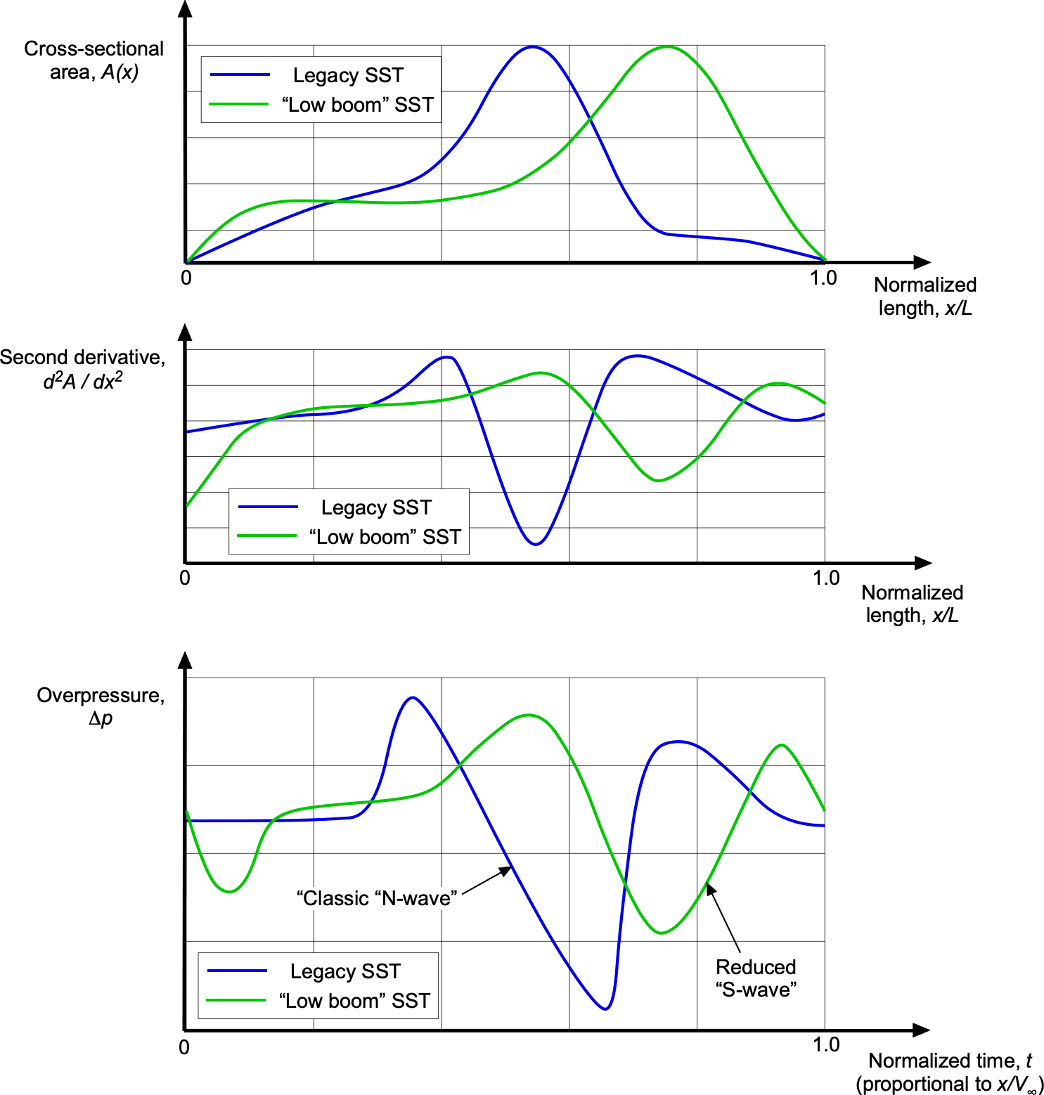
In contrast, a “low boom” design, such as predicted for the X-59 demonstrator, uses a long forebody and smoothly blended cross-sectional area and volume changes. The cross-sectional area increases gradually, peaks further aft, and exhibits gentler curvature throughout, lowering the magnitude of , and so producing a ground signature composed of lower-amplitude pressure disturbances. Notice that the more “S-wave” shaped boom reduces both the peak overpressure and the rate of pressure rise, thereby minimizing acoustic intensity and startling effects to an observer on the ground.
Atmospheric Conditions
Atmospheric conditions can also influence the strength and reach of sonic booms. Temperature gradients and wind shear can refract shock waves upward or laterally, potentially reducing their intensity at the surface. Concepts such as “boomless cruise” aim to take advantage of these effects by operating in regions and altitudes where shock waves are refracted away from the ground. However, most of the U.S. and much of the world do not experience the kind of persistent atmospheric profiles required to bend sonic booms upward with any predictable reliability. In the troposphere, temperature generally decreases with altitude, which causes shock waves to refract downward rather than upward. Even under favorable conditions, such as temperature inversion, slight variations in humidity, turbulence, or terrain can still scatter acoustic energy back toward the ground. The lateral spread of a sonic boom often extends 50 miles or more, making it likely that people far from the flight path will still hear it. Therefore, while atmospheric refraction may alter the footprint of the sonic boom, it does not offer a reliable or practical method for sonic boom mitigation.
From an operational and regulatory perspective, relying on atmospheric refraction to mitigate sonic booms introduces substantial uncertainty. Exploiting such effects would require high-resolution, real-time knowledge of upper-atmosphere temperature, humidity, and wind profiles along the entire flight path, data that are difficult to obtain and rapidly variable. Even minor deviations in these conditions can shift the location and intensity of the refracted shock waves, making it impossible to guarantee a consistently quiet ground footprint. Moreover, regulatory agencies such as the FAA and EASA will follow the standards set by the ICAO, which will require predictable and repeatable noise signatures to certify overland supersonic operations. Consequently, sensible boom mitigation efforts will remain focused on deterministic strategies such as airframe shaping and other low-boom design principles, independent of atmospheric variability.
Check Your Understanding #5 – Sonic boom intensity comparison
Boom Supersonic has developed a scaled demonstrator aircraft, the XB-1, to test technologies intended for their future commercial supersonic airliner, the Overture. Assume both aircraft cruise at similar altitudes, and use Whitham’s theory to estimate the relative ground-level sonic boom overpressures and sound pressure levels (SPL). Assume both aircraft fly at the same cruise altitude . The known information is:
- = = 1.2 = Mach number of the XB-1; = = 1.7 = Mach number of Overture.
- =
 = 6,123 kg = weight of the XB-1; =
  = 77,111 kg = weight of Overture.
- Estimate the ratio
 , the ground-level peak overpressure of Overture compared to the XB-1.
 - Estimate the corresponding increase in sound pressure level (SPL), in decibels.
- Discuss the implications of your results for overland supersonic flight.
Show solution/hide solution.
- According to Whitham’s theory, the peak overpressure at the ground scales as
![\[ \Delta p \ \propto \ \frac{W}{h^2} \, M_{\infty}^3 \]](https://eaglepubs.erau.edu/app/uploads/quicklatex/quicklatex.com-fb9badc9a0896f910279e1889f277d63_l3.svg "Rendered by QuickLaTeX.com")
The sound pressure level (SPL) is defined as
![\[ \text{SPL} = 20 \log_{10} \left( \frac{\Delta p}{p_0} \right) \]](https://eaglepubs.erau.edu/app/uploads/quicklatex/quicklatex.com-22163db4962663b6fbe482f8640bdb26_l3.svg "Rendered by QuickLaTeX.com")
where
 Pa is the reference sound pressure. Using the scaling law gives
![\[ \frac{\Delta p_2}{\Delta p_1} = \frac{W_2}{W_1} \left( \frac{M_2}{M_1} \right)^3 = \frac{77,111}{6,123} \left( \frac{1.7}{1.2} \right)^3 = 12.6 \times 2.84 = 35.8 \]](https://eaglepubs.erau.edu/app/uploads/quicklatex/quicklatex.com-9f69f9d70ea6caf55d1f030f8cb4d971_l3.svg "Rendered by QuickLaTeX.com")
This result shows that: 1. The weight difference alone contributes a factor of
 . 2. The Mach number difference contributes a factor of
  . Therefore, the predicted ground-level overpressure of the Overture is approximately 36 times greater than that of the XB-1.
 - Using the SPL relationship, then
![\[ \Delta \text{SPL} = 20 \log_{10} \left( \frac{\Delta p_2}{\Delta p_1} \right) \]](https://eaglepubs.erau.edu/app/uploads/quicklatex/quicklatex.com-9d7344f634cc921d4bf6e4cf8474ff7e_l3.svg "Rendered by QuickLaTeX.com")
Substituting values gives
![\[ \Delta \text{SPL} = 20 \log_{10}(35.8) = 20 \times 1.554 = 31.1~\text{dB} \]](https://eaglepubs.erau.edu/app/uploads/quicklatex/quicklatex.com-8924bb9bd34e114b7a12003a72d62218_l3.svg "Rendered by QuickLaTeX.com")
Therefore, the SPL of Overture is approximately 31 dB higher than that of the XB-1.
- An SPL increase of 31 dB represents more than an eightfold increase in perceived loudness. While XB-1 may have produced acceptable boom levels during test flights, the raw sonic boom from Overture would be unacceptable for overland operations. As a reference, on return to Earth, the Space Shuttle had a typical landing weight of about 100,000 kg, and it produced unmistakable sonic booms that were widely heard along its descent path. However, these events were rare, highly publicized, and generally expected by the public, which helped mitigate complaints. Even so, the startling character of the boom was still apparent, illustrating the challenge of public tolerance for high-intensity supersonic events, regardless of frequency. The Concorde, with a typical landing weight of about 111,000 kg (somewhat higher than that of Overture), was banned[16] from overland routes in the United States after public backlash during early supersonic test flights in the 1970s. Although Concorde‘s boom was well understood and predictably narrow in footprint, its regular occurrence proved intolerable. These two examples demonstrate that both the strength and frequency of sonic booms are critical factors in public acceptability, reinforcing the need for reliable boom mitigation strategies in future SST development.
Any Future for SSTs?
The Anglo-French Concorde remains the only successful SST to date. Although many other SST designs have been studied, whether any future concept will prove economically viable for scheduled airline service remains to be seen. The inherently lower lift-to-drag ratios of an aircraft flying at supersonic speeds, even if the wing and airframe are highly aerodynamically and structurally optimized, mean SSTs will always burn significantly more fuel than subsonic designs. Consequently, the maximum achievable range of a supersonic airliner will always be less than that of a subsonic aircraft. Like the Concorde, transatlantic routes for a Mach 2 capable SST are undoubtedly technically and economically feasible, with an optimally designed SST. However, longer routes, such as from the U.S. to Asia or Australia, would require refueling stops, likely eroding any speed advantage, particularly for a Mach 1.5 to 1.7 capable SST. Additional routing detours to avoid sonic booms over land may further reduce the practical benefit of higher cruise speeds unless the SST can sustain Mach 2 or greater.
Costs
The resulting seat-mile costs for an SST will undoubtedly be higher than those of subsonic airplanes, perhaps three to five times more, despite the advantage to passengers of shorter flight times. Therefore, to be commercially viable, airlines would need to charge significantly higher fares for an SST, limiting the market to passengers willing to pay a premium. As a reference, Concorde tickets in the 1990s typically cost US$10,000–12,000 round trip (equivalent to US$18,000–20,000 or more today). While reduced travel times may appeal to some passengers, particularly for the novelty of flying supersonically, passengers historically shop for travel based on price. Therefore, the economics of an SST will remain difficult to justify for both airlines and manufacturers. Maintenance and repair costs are also likely to be significantly higher for an SST due to the thermal and mechanical stresses imposed on the airframe and propulsion systems during high-speed cruise, which can potentially increase downtime and reduce aircraft availability.
Certification
Certification remains a significant hurdle for any proposed SST and will likely involve a lengthy and uncertain process. Concorde underwent more than 4,000 hours of certification testing over seven years, plus 1,000 hours of route-proving under airline operating conditions. A more fundamental obstacle today is that civil supersonic flight over land remains prohibited in both the U.S. and Europe due to the disruptive effects of sonic booms. Regulatory frameworks such as FAA Part 36 (Noise Standards) and ICAO Annex 16, Volume I, mandate noise certification procedures but provide no standards for acceptable sonic boom loudness. Although efforts are underway to define a low-boom certification metric, no enforceable regulatory pathway exists. Unless these prohibitions are revised, demonstrating low-boom capability will not be enough because a viable SST must ultimately comply with yet-to-be-defined regulatory limits on boom intensity and community impact. Until then, overland routes served by any future SSTs will remain restricted, limiting flexibility and reducing the aircraft’s commercial appeal. Additional operational limitations may arise at airports because of noise abatement issues or runway length requirements.[17]
Optimization or Optimism?
Pursuing a new SST can be seen as either an ambitious exercise in optimization or a stubborn reinvention of a concept that history has already judged. The potential SST players of the future face immense technical, certification, and economic challenges, along with a hefty dose of public skepticism. None of the major civil airframe manufacturers is pursuing supersonic flight. In contrast, smaller supersonic aircraft such as supersonic business jets (SSBJs) have received somewhat more recent attention. Several companies have proposed SSBJ concepts to transport between 10 and 80 passengers. Typically, these aircraft would be about twice the size of a conventional business jet but still much smaller than the Concorde. Yet the technical and certification issues remain, and the economics remain speculative.
One startup, Boom Supersonic, claims to have a Mach 1.7 capable SST called Overture in development and expects it to enter service with airlines by 2029. Beyond the fundamental issues of the sonic boom, a major technical hurdle remains: the lack of a suitable propulsion system. No engine manufacturers currently produce quiet, fuel-efficient engines optimized for supersonic cruise, even as low as Mach 1.7, that meet civil certification requirements. Developing and certifying a new supersonic-capable engine for civil use could take a decade or more, given the absence of existing engine types that meet both supersonic performance and current noise and emissions regulations. Nevertheless, several groups argue that combining technical innovation, market demand, and environmental adaptation could open the door to a new era of sustainable supersonic travel. However, in light of the well-known challenges and others that may yet emerge, this remains highly speculative. For now, it is fair to say that fare-paying passengers are unlikely to be flying supersonic again anytime soon.
Summary & Closure
Humans have long aspired to fly faster, a pursuit that has driven the development of aerodynamically refined airframes and advanced propulsion systems for supersonic flight. Despite decades of progress, the realization of practical, routine supersonic transportation still presents formidable engineering challenges. These include the need to minimize wave drag and shock interactions through precise shaping of the airframe, as well as the development of propulsion systems capable of maintaining high efficiency at supersonic speeds. Continued advances in aerodynamics, propulsion, and high-temperature materials are essential to enabling future breakthroughs in high-speed flight.
Beyond technical barriers, the economics of supersonic transport are equally complex. The research, design, testing, and certification of supersonic aircraft demand significant financial investment, which must be recovered through sales and operations. Manufacturing costs are substantially higher than those for conventional subsonic aircraft due to the need for specialized materials and production techniques. In operation, supersonic aircraft consume more fuel per passenger-mile or passenger-kilometer and are likely to incur higher maintenance costs. As a result, airlines must impose premium pricing to maintain profitability. The commercial viability of any future supersonic transport will ultimately depend not only on technological maturity but also on market demand and its ability to compete with established subsonic alternatives.
5-Question Self-Assessment Quickquiz
For Further Thought or Discussion
- Do some background research to determine what efforts are being explored to reduce the intensity of the “sonic boom” produced by supersonic airplanes.
- Research some engineering issues associated with kinetic heating on a supersonic airplane that cruises between Mach 2 and 3. What kinds of construction materials might be required?
- What kinds of supersonic passenger airplanes, i.e., SSTs, might there be in the future? Explain why their success ultimately depends on the availability of an engine suitable for supersonic flight.
- Study the image below, which is a schlieren flow visualization image of what is produced when a bullet is fired from a gun. Can you explain what is happening here and the origin of all the waves?
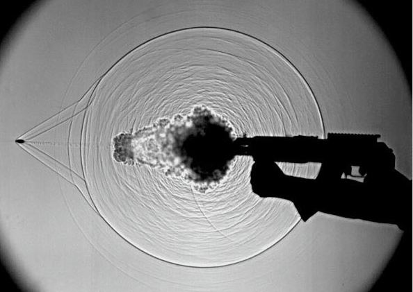
- Consider the Mach angle as a function of the Mach number. What happens to the Mach angle at hypersonic Mach numbers, and why is this important?
Other Useful Online Resources
For additional resources on supersonic flight, follow up on some of these online resources:
- Airplanes approaching the sound barrier – another film by Shell Oil.
- High-speed flight: Part 1, and Parts 2 & 3.
- Video about the World’s fastest subsonic airliner: The Convair 990A Coronado.
- The Insane Engineering of the X-15 – see the video here.
- The Lockheed A-12 – speed matters!
- The SR-71 Blackbird – the king of speed!
- Project canceled: BAC TSR2 – The British Cold War strike and reconnaissance aircraft that was canceled.
- Great video about the English Electric Lightning –The British supersonic fighter and interceptor aircraft.
- Video about the World’s fastest bomber: The Mach 3 capable XB-70 Valkyrie.
- Death of a Valkyrie: The 1966 XB-70 Midair Collision
- Kelly Johnson and the Skunk Works. The genius who changed aviation.
- The author gratefully acknowledges his teacher, Professor Bryan Edward Richards. After graduating in 1960, Professor Richards joined the British Aircraft Corporation (BAC), where he contributed to the design of Concorde and its supersonic aerodynamics. He earned his Ph.D. in 1966, focusing on research in hypersonic film cooling. He later became a professor at the Von Kármán Institute in Belgium, where he led research in hypersonic aerodynamics until 1979. He then served as the Mechan Chair of Aeronautics at the University of Glasgow, where he taught and conducted research in high-speed aerodynamics and computational fluid dynamics until his retirement in 2003.
 ↵
↵ - Some of the most notable were in Germany. See: Peter Wegener, "The Peenemünde Wind Tunnels – A Memoir," Yale University Press, 1996. ↵
- Ackert, J., "Luftkräfte auf Flügel, die mit größerer als Schallgeschwindigkeit bewegt werden" in the journal Zeitschrift für Flugtechnik und Motorluftschiffahrt. ↵
- One solution was using dive recovery flaps or airbrakes designed to disrupt the airflow over the wings and tail surfaces, reducing the nose-down pitching tendency during high-speed dives. ↵
- A related application of this relation involves determining the conditions under which the post-shock Mach number drops to unity, known as the sonic line. This delineates the boundary between attached and detached shock behavior. ↵
- Notice: All angles are expressed in radians. ↵
- Indeed, this is the physical explanation of the "Mach tuck" phenomenon noticed on early airplanes as they began to approach the speed of sound. ↵
- An exception may be the Boom Overture design, yet unflown, which has more average wing sweep than needed for a Mach number of 1.7. ↵
- The British Airways Concorde fleet made 50,000 flights and collectively flew more than 2.5 million passengers. ↵
- NASA Technical Note D-3767: "A Concept of the Vortex Lift of Sharp-Edge Delta Wings Based on a Leading-Edge-Suction Analogy." ↵
- NASA Technical Note D-4739: "Application of the Leading-Edge-Suction Analogy of Vortex Lift to the Drag Due to Lift of Sharp-Edge Delta Wings." ↵
- Which may extend out 50 or more miles. ↵
- The disturbance introduced into the flow can be modeled as a series of local "piston" motions perpendicular to the surface. These create weak compressive waves that coalesce into a shock wave. ↵
- Whitham, G. B., "The Flow Pattern of a Supersonic Projectile," Communications in Pure and Applied Mathematics, Vol. V, No. 3, Aug. 1952, pp. 301–348. ↵
- This result is also related to Whitcomb's area rule scaling in that changes in cross-section should be kept as smooth and as gradual as possible. ↵
- In 1973, the U.S. Federal Aviation Administration (FAA) issued a regulation prohibiting commercial supersonic flight over land because of unacceptable sonic boom noise levels observed during Concorde testing. See 14 CFR § 91.817. ↵
- It is fair to say that any SST will not have short-field takeoff capabilities. ↵
