46 Rocket Engines
Introduction[1]
Rocket engines launch payloads, such as satellites and space probes, into Earth’s orbit. They are also used to propel spacecraft that are already in space. The flow through a rocket nozzle typically involves accelerating hot gases produced by the combustion of a propellant from subsonic to supersonic speeds, converting thermal energy into directed kinetic energy. By imparting a time rate of change of momentum to the gas flow, a force is applied from the rocket engine(s) to the vehicle. Before being expelled from the engine(s), the propellant can be stored in separate fuel and oxidizer tanks, or as a solid mixture of the two. Rocket engines are non-air-breathing, so they require a fuel and an oxidizer, known as a propellant.
Four types of rocket engines can be used for different and relevant applications:
- Launch Vehicles: The rocket engines used in launch vehicles are designed to provide high thrust and momentum, lifting the vehicle off the ground and into space. They must be powerful enough to overcome Earth’s gravity and give the required kinetic and potential energy for the spacecraft and its payload to reach orbit.
- Spacecraft: Rocket engines are designed to propel and maneuver vehicles already in space. They are typically smaller and less powerful than the engines used for launch vehicles. Still, they must be highly reliable, efficient, and versatile to enable the spacecraft to travel long distances and perform complex missions.
- Missiles: Rocket engines used in missiles usually operate on solid fuel and are designed to provide the speed and maneuverability to carry warheads or other payloads to their targets. Missiles must be highly precise and reliable and may need to operate in various flight conditions and environments.
- Miscellaneous: There are other applications for rockets, including suborbital flights, scientific experiments, and recreational activities such as model rocketry. These types of rocket engines may have specialized requirements depending on their specific use.
Learning Objectives
- Understand the basic principles of rocket propulsion systems.
- Distinguish between the different types of rocket engines and their respective purposes.
- Appreciate the concept of impulse and specific impulse as measures of rocket efficiency.
- Know how to calculate the thrust of a rocket engine.
- Be aware of the factors that affect the performance and efficiency of rocket motors.
Rocket Propulsion Fundamentals
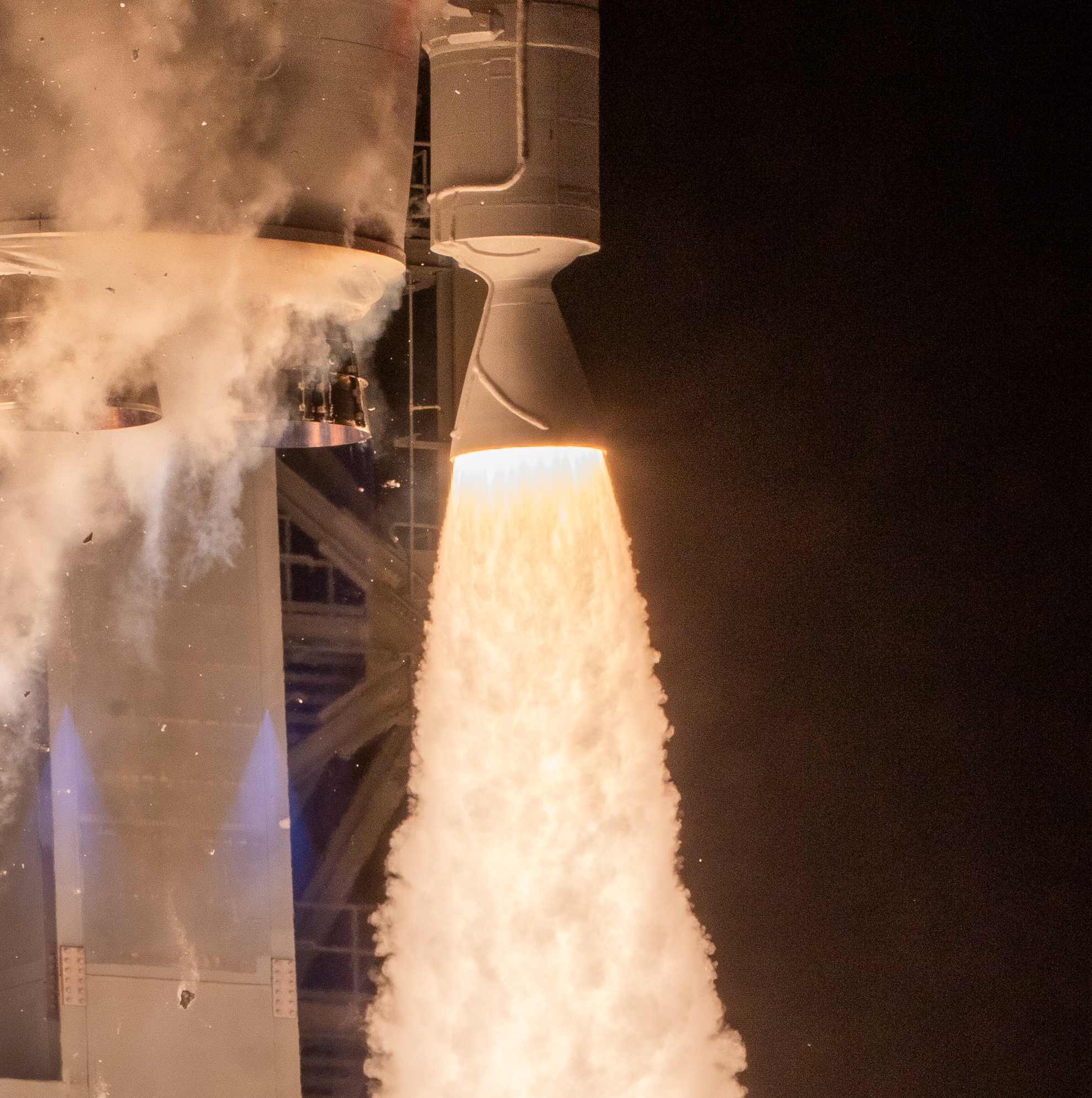
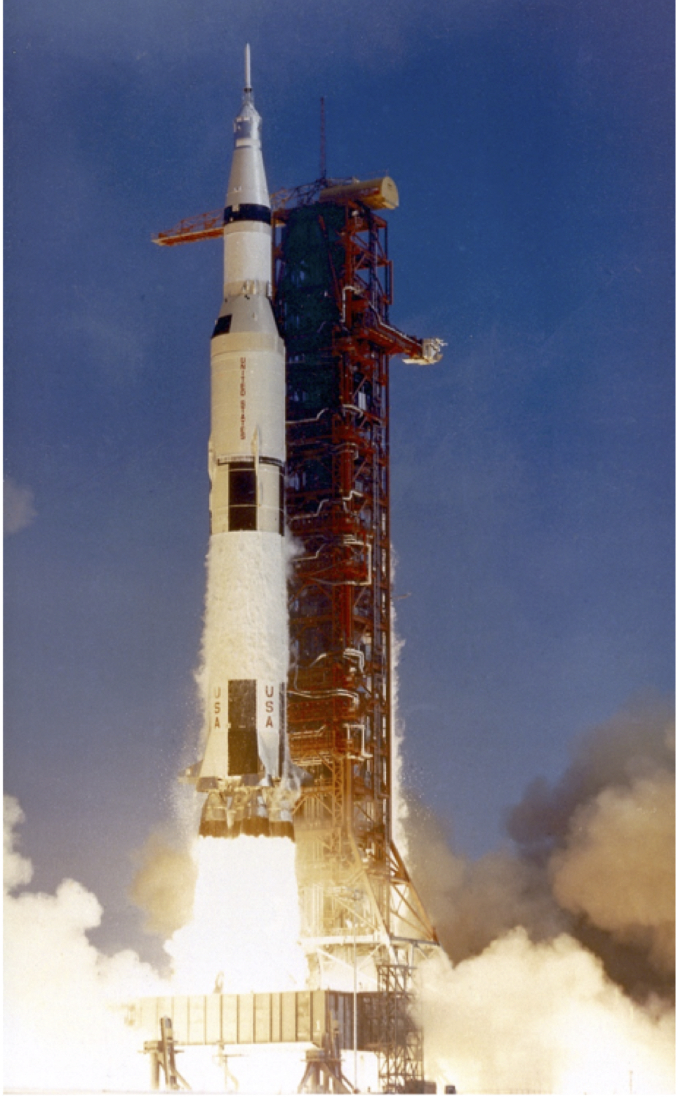
In a rocket engine, the propellants, i.e., a fuel and an oxidizer, undergo combustion at high pressures and temperatures to produce the necessary thrust. Notice that, unlike an air-breathing engine, the oxidizer must be carried along with the fuel for a rocket engine. The fastest way to liberate energy is through combustion, which creates a high-speed gas flow that can be expanded through a nozzle at high velocity and Mach number, producing high thrust. An example of a rocket engine operating at full thrust is shown in the photograph below, which shows a solid-propellant booster. Other types of rocket engines can use liquid propellants (fuel and oxidizer) or a hybrid liquid/solid propellant.
A rocket engine must be designed to withstand the combustion pressures and temperatures, along with safety margins. The shape and length of the combustion chamber and exit nozzle are essential design parameters for a rocket engine. The combustion chamber must be sufficiently long to allow complete propellant combustion before the hot gases enter the nozzle, ensuring efficient combustion and maximizing thrust. The length of the combustion chamber is typically determined by several factors, including the type of propellant used, combustion efficiency, and the desired overall performance characteristics of the rocket engine in relation to the mission profile.
Rocket engines operate at extremely high temperatures, usually between 2,500 K and 3,500K. Therefore, the combustion chamber and nozzle must be actively cooled to dissipate the heat generated during combustion, thereby preventing overheating and structural failure. With liquid-fueled rocket engines, this process is accomplished by circulating cold fuel around channels or jackets within the walls of the combustion chamber and nozzle. The fuel absorbs the heat by conduction and convects it away, allowing the rocket to operate safely for extended periods. A byproduct is that more efficient combustion is obtained by preheating the fuel before it is combined with the oxidizer. In solid-fuel rocket engines, which typically operate for relatively short times, the nozzle is made of high-temperature materials that can be ablatively cooled, i.e., the material sheds its surface in layers, carrying the absorbed heat energy.
Application of Conservation Principles
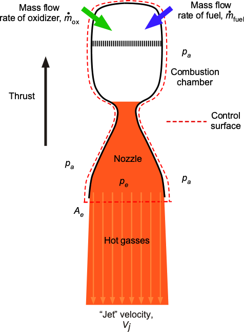
Newton’s second and third laws are fundamental physical principles that govern the operation of rocket propulsion systems. Consider a typical rocket engine, as shown in the figure below. The principle of thrust generation for a rocket engine is based on the reaction force associated with accelerating a mass of gases at high velocity out of an expansion nozzle. The gases are a byproduct of the combustion of the fuel and the oxidizer, which increases their kinetic energy and momentum. Consequently, the gases and products of combustion are accelerated in one direction, and the resultant force on the rocket engine and the vehicle to which it is attached is directed in the opposite direction, per Newton’s third law.
If the flow is assumed to be steady, compressible, and inviscid, then the general form of the momentum equation is
(1) 
The pressure integral on the left-hand side can be written as
(2) 
The throat area is much smaller than the exit area, so the pressure integral value at the throat can be assumed to be zero.
The force on the fluid to change its momentum, which by Newton’s 3rd law, is in the opposite direction to the thrust,  . Therefore, the momentum equation becomes
(3) 
If the flow can be assumed to be one-dimensional, which by any standard is a reasonable one, the thrust produced by the rocket engine will be
(4) 
where  is the exit pressure at the nozzle,
  is the ambient pressure,
  is the exit area,
  is the exit or jet velocity, and
  is the propellant mass flow rate. The first term accounts for the momentum of the exhaust gases, and the second term accounts for the net pressure force on the exit plane. Remember that there is no external mass flow into a rocket engine, i.e., no value of
  , as with an air-breathing engine.
The first term on the right-hand side of Eq. 4, i.e., the  term, is a momentum flow rate or time rate of change of momentum. The second term is the net force resulting from a pressure difference between the exit gases and the ambient pressure. For a rocket, the time rate of change of momentum is much larger than any pressure force, i.e.,
  . If
. If  , the pressure force term is zero. In this case, the thrust produced is a maximum, and the nozzle is said to be ideally or optimally expanded; this condition is a design goal for a rocket engine.
For a rocket engine, especially when its performance characteristics are being compared, it is often useful to write for the net thrust that
(5) 
where  is called an equivalent exhaust velocity that includes the pressure term, i.e.,
(6) 
In practice, however, the pressure term is relatively small because the nozzle is generally designed for (or close to) ideal expansion where , so the value of is very close to  . For this reason, the jet or exhaust velocity is designated as in most practical contexts.
Check Your Understanding #1 – Calculation of rocket thrust
Compare the thrust and efficiency of a rocket engine versus a turbojet engine at a flight speed of 200 m/s. Both engines exhaust the flow with a mass flow of 40 kg/s. The rocket exhausts at a velocity of 3,000 m/s, and the turbojet at 800 m/s. Assume that the exhaust flow is ideally expanded in both cases.
Show solution/hide solution.
The thrust produced by the rocket engine with ideal expansion will be
![\[ T = \overbigdot{m} \, V_j \]](https://eaglepubs.erau.edu/app/uploads/quicklatex/quicklatex.com-7a35eadaf93ad70b6e65ac3d95eba9ad_l3.svg "Rendered by QuickLaTeX.com")
where is the jet or exit velocity and is the propellant mass flow rate. Inserting the numerical values gives
![\[ T = \overbigdot{m} \, V_j = 40.0 \times 3,000 = 120.0~\mbox{kN} \]](https://eaglepubs.erau.edu/app/uploads/quicklatex/quicklatex.com-7cf6c6741f5a39d0ae341f40eadcad13_l3.svg "Rendered by QuickLaTeX.com")
Remember that a rocket engine is not air-breathing, so there is no inlet mass flow rate.
The thrust produced by the turbojet engine with ideal expansion will be
![\[ T = \overbigdot{m} \, \left( V_j - V_{\infty} \right) \]](https://eaglepubs.erau.edu/app/uploads/quicklatex/quicklatex.com-08fc98dc4fe8f7bf97559728779070bf_l3.svg "Rendered by QuickLaTeX.com")
where is the airspeed and inlet velocity. Inserting the numerical values gives
![\[ T = \overbigdot{m} \, \left( V_j - V_{\infty} \right) = 40.0 \times \left( 800.0 - 200.0 \right) = 24.0~\mbox{kN} \]](https://eaglepubs.erau.edu/app/uploads/quicklatex/quicklatex.com-3c4fb1bebae89fc67a5b56a40fe996aa_l3.svg "Rendered by QuickLaTeX.com")
The propulsive efficiency  is defined as
![\[ \eta_p = \frac{2 V_{\infty}}{V_j + V_{\infty}} \]](https://eaglepubs.erau.edu/app/uploads/quicklatex/quicklatex.com-db56d407f691a7febb102d842289051b_l3.svg "Rendered by QuickLaTeX.com")
For the turbojet with = 800 m/s and = 200 m/s, then
![\[ \eta_p = \frac{2 \times 200}{800 + 200} = \frac{400}{1,000} = 0.40 \quad \text{or } 40\% \]](https://eaglepubs.erau.edu/app/uploads/quicklatex/quicklatex.com-0a5b7a7af4763319808110ddfc5d4c04_l3.svg "Rendered by QuickLaTeX.com")
For the rocket, assuming the same flight speed = 200 m/s and = 3,000 m/s, then
![\[ \eta_p = \frac{2 \times 200}{3,000 + 200} = \frac{400}{3,200} = 0.125 \quad \text{or } 12.5\% \]](https://eaglepubs.erau.edu/app/uploads/quicklatex/quicklatex.com-49eeab20b73161007a90f9ee5a6c0e28_l3.svg "Rendered by QuickLaTeX.com")
Therefore, while the rocket engine delivers higher thrust by expelling mass at a much higher velocity, it does so with significantly lower propulsive efficiency. The turbojet achieves better efficiency by matching the jet velocity more closely to the flight speed.
Nozzle Shape
The nozzle is designed to accelerate the high-pressure, high-temperature gases generated in the combustion chamber to a supersonic exit velocity. As shown in the figure below, the nozzle typically has two sections: the convergent and divergent sections. The resulting shape is often referred to as a nozzle bell.” The convergent section narrows the flow area, increasing the gas velocity as it passes through and accelerating it to supersonic conditions.
The convergent section then leads to the throat, the narrowest part of the nozzle. Beyond the throat, the divergent area widens, allowing the supersonic gases to expand and accelerate to their final velocity, . Ideally, this expansion continues smoothly and progressively until the hot gases reach the nozzle exit.
Therefore, the design of the nozzle, including the length and shape of the divergent section, is critical in achieving optimal thrust performance from the rocket engine. Generally, the nozzle must be long enough and the exit area large enough to ensure the exit pressure is close to the ambient pressure outside the nozzle. This feature is essential for maximizing the propulsion system’s efficiency and achieving maximum thrust.
Exhaust Gas Velocity
As combustion gases enter a nozzle, they initially travel at subsonic velocities. As the nozzle’s cross-sectional area contracts toward the throat, the gas is forced to accelerate until its velocity reaches sonic speed there, where the cross-sectional area is smallest. Downstream of the throat, the cross-sectional area increases again in the diverging section of the nozzle, allowing the gas to expand and accelerate to progressively higher supersonic velocities. This acceleration process converts thermal energy into directed kinetic energy, producing thrust.
Thermodynamic principles can be used to derive an expression for the exhaust velocity. The approach utilizes energy conservation, assuming isentropic, compressible, two-phase flow. The exhaust velocity is given by
(7) 
where is the exit pressure,  is the chamber or combustion pressure,
  is the ratio of the specific heats of the propellant gas,
  is the universal gas constant,[2] and
  is the relative molecular mass of the propellant. Because the combustion process happens so quickly, it can be considered isothermal, meaning that the combustion chamber and exhaust gas temperatures are equal, i.e.,
  constant. Equation 7 assumes the expansion through the nozzle is adiabatic and reversible (isentropic) and that the exhaust gases behave as an ideal gas. The nozzle accelerates the gas by converting internal thermal energy into kinetic energy, thereby maximizing the exhaust velocity and producing thrust.
For in-space operations, i.e., in a vacuum, Eq. 7 can be approximated by
(8) 
It has been found that  for most rocket engines, but this value depends on the specific engine design. If the combustion temperature,
  , is expressed in units of Kelvin, the units of in Eq. 8 will be in terms of kilometers per second (km/s).
Typical values of for different types of rocket propellants range from approximately 1,700 to 2,900 m/s for liquid monopropellant engines, 2,900 to 4,500 m/s for liquid bipropellant engines, and 2,100 to 3,200 m/s for solid propellant rocket engines. These values are consistent with experimental data and operational rocket engines. For example, consider combustion gases with a chamber pressure of = 7.0 MPa, an exit pressure of = 0.1 MPa, a combustion temperature of = 3,500 K,  = 1.2, and = 22. Substituting these values into the exhaust velocity equation yields an exit velocity of
  2,800 m/s, which is consistent with typical solid and bipropellant engine performance.
Nozzle Efficiency
Designing rocket engines for launch vehicles that can operate efficiently across a wide range of in-atmosphere altitudes is a significant engineering challenge that requires careful consideration of many factors. These factors include the nozzle’s shape and size, the nozzle’s materials, the propellant flow rate, the combustion characteristics of the fuel and oxidizer, and the cooling system(s). Designers aim to achieve the best possible performance of the rocket engine across the entire altitude range of a rocket’s atmospheric flight, thereby maximizing thrust and efficiency. Rocket engines must also be optimized for efficiency in the vacuum of space.
When the exhaust pressure at the nozzle exit matches the ambient pressure, it is referred to as ideal or optimum expansion, as illustrated in the figure below. In this ideal state, there is no pressure gradient, and all exhaust gases are directed away from the engine. This situation results in the maximum thrust because nearly all the exhaust gas’s momentum is converted into thrust. This operating condition enables rocket engines to achieve their highest possible performance in terms of thrust and efficiency. However, achieving optimal expansion requires careful design and optimization of the bell’s shape.
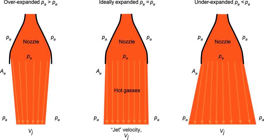
Over-expansion means that the external (atmospheric) pressure, , is higher than the exit pressure, . When an over-expanded flow passes through the nozzle, the higher external pressure at the exit produces a positive (or adverse) pressure gradient that slows the jet flow, and the jet flux subsequently converges as it exits the nozzle. The pressure difference may be high enough to cause the flow to separate from the nozzle’s walls. Over-expansion of the gas flow reduces the thrust and efficiency of the engine. The solution, in this case, is to use a shorter bell.
The opposite situation, where the atmospheric pressure is lower than the exit pressure, resulting in an adverse pressure gradient, is called an under-expanded flow. In this case, the flow continues to develop and expand outward after exiting the nozzle, so this process does not contribute to thrust production. The solution for thrust recovery in this case is a larger, longer bell. When designing rocket engines for launch vehicles that must operate in the atmosphere, the nozzle may be designed for slight overexpansion at sea level, recognizing that the exhaust pressure at the nozzle exit will likely be lower than the ambient air pressure. This design approach can better optimize the rocket engine’s performance across a larger portion of the launch profile, allowing it to maximize overall thrust and efficiency throughout the atmosphere.
Many rocket engines, including the Merlin used in the Falcon 9, feature a nozzle designed to operate efficiently across a wide range of altitudes, from sea level to the stratosphere, where pressure is extremely low. The RS-25 engines, first used in the Space Shuttle program, were optimized for sea-level operation during the launch’s initial phase and then transitioned to vacuum-optimized operation. To this end, the RS-25 engine has a movable nozzle extension to optimize its performance. When rocket engines operate at sea level, the nozzles are typically designed to produce a slightly over-expanded condition, allowing them to become more ideally expanded with increasing altitude in the atmosphere.
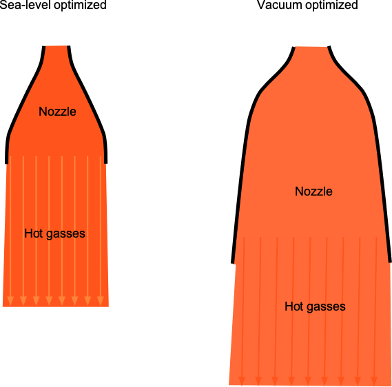
It will be noted that second- or upper-stage “vacuum-optimized” rocket engines have significantly larger nozzles than those used on sea-level (or atmospheric) optimized engines, as shown in the figure below. The Merlin second-stage engine is a good example. The second stage, “vacuum-optimized” Merlin, uses the largest practical nozzle to achieve an ideal expansion of the exhaust gases. The vacuum-optimized Merlin engine features a larger exhaust section and a significantly higher expansion nozzle ratio of 165:1, compared to the sea-level-optimized version, which has a smaller 16:1 expansion nozzle ratio. The larger nozzle enables more ideal, more efficient expansion of the exhaust gases in the vacuum of space, thereby maximizing propulsive thrust and efficiency.
“Over-Expanded” Versus “Under-Expanded”?
Remember that the nozzle is designed to accelerate the exhaust gases and convert the thermal energy of combustion into kinetic energy. At lower altitudes, the external atmospheric pressure is higher than at higher altitudes. This means that the exhaust gases from the rocket engine encounter higher external pressure as they expand supersonically to reach the nozzle exit diameter. This higher external pressure resists the flow’s expansion, so the flow “over-expands” within the nozzle’s limits. The external ambient pressure is lower at higher altitudes, allowing the flow to expand more quickly. However, as the flow reaches the nozzle exit, it may not have expanded enough, resulting in an “under-expanded” gas flow.
Supersonic Flow Through a Rocket Nozzle
The details of the flow through a rocket nozzle can now be explained in more detail. In the aerodynamic and thermodynamic analysis of the nozzle, the flow is assumed to pass through three primary regions, as shown in the figure below: 1. A converging section where subsonic flow is accelerated; 2. A throat where the flow becomes sonic or choked; 3. A diverging or “bell” section where the flow rapidly expands to supersonic velocities. This convergent-divergent nozzle is commonly referred to as a De Laval nozzle after Gustaf de Laval, which was first applied to a rocket by Robert Goddard. Again, the flow is governed by the conservation of mass, momentum, and energy, along with the assumption of isentropic, one-dimensional behavior of an ideal gas.
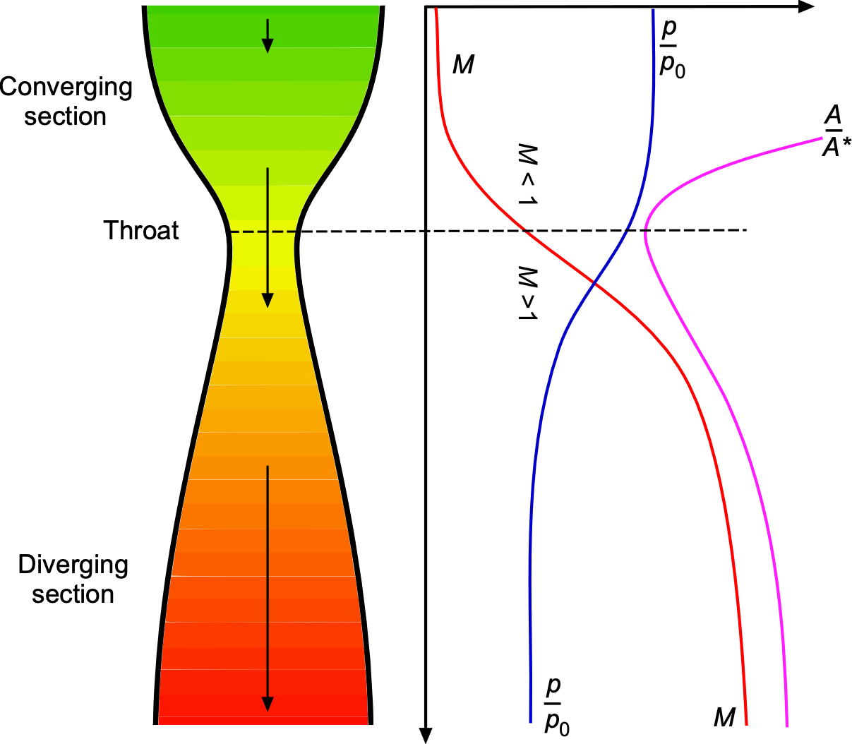
To describe the flow in such a nozzle, several gas-dynamic relations can be used. The area-Mach number relation is given by
(9) ![\begin{equation*} \frac{A}{A^*} = \frac{1}{M} \left[ \frac{2}{\gamma + 1} \left(1 + \frac{\gamma - 1}{2} M^2 \right) \right]^{\tfrac{\gamma + 1}{2(\gamma - 1)}} \end{equation*}](https://eaglepubs.erau.edu/app/uploads/quicklatex/quicklatex.com-165cbeafe791ddae603859ec1ebb89dd_l3.svg "Rendered by QuickLaTeX.com")
where  is the area at the sonic throat,
  is the local Mach number, and is the specific heat ratio. This equation determines the Mach number as a function of cross-sectional area and is fundamental to nozzle design.
The thermodynamic quantities also vary with Mach number. The ratio of static to stagnation temperature is given by
(10) 
and the corresponding pressure ratio is
(11) 
The velocity of the flow at any point in the nozzle can be derived from the energy equation. At the exit of the nozzle, where the Mach number is supersonic, the exit velocity is given by
(12) ![\begin{equation*} V_e = \sqrt{\frac{2\gamma}{\gamma-1}R \, T_0 \left[1-\left(\frac{p_e}{p_0}\right)^{\tfrac{\gamma-1}{\gamma}}\right]} \end{equation*}](https://eaglepubs.erau.edu/app/uploads/quicklatex/quicklatex.com-f70155fc2c3ac467436bc832239e04d8_l3.svg "Rendered by QuickLaTeX.com")
where  and
and  are the stagnation temperature and pressure in the chamber, respectively, is the exit pressure, and
  is the gas constant.
When the flow is choked at the throat, i.e.,  , the mass flow rate through the nozzle is fixed and can be expressed as
(13) 
As previously discussed, the total thrust produced by the nozzle consists of two components, i.e., the momentum thrust and the pressure thrust. Therefore, the total thrust is
(14) 
where is the nozzle exit area and is the ambient pressure.
Recall that if the exit pressure equals the ambient pressure, the nozzle is said to be ideally expanded and the thrust is maximized. If the exit pressure is less than the ambient pressure, the flow is overexpanded, which may lead to internal shocks or flow separation. Conversely, if the exit pressure exceeds the ambient pressure, the flow is underexpanded and continues to expand outside the nozzle. Both overexpansion and underexpansion lead to losses of thrust-producing efficiency, as previously explained.
These relations form the basis for analyzing the performance of rocket nozzles under both ideal and off-design conditions. The following numerical example demonstrates the core computations involved in analyzing an ideal rocket nozzle operating at sea level.
Check Your Understanding #2 – Supersonic flow through a nozzle
Consider an ideal, isentropic flow of combustion gases through a de Laval nozzle. The objective is to determine the thrust produced. The key parameters are:
- Chamber stagnation pressure), = 7.0
 10
10 Pa
Pa - Chamber stagnation temperature, = 3,500 K
- Specific heat ratio, = 1.22
- Gas constant, = 355 J kg
 K
K - Throat area, = 0.01 m

- Exit area, = 0.05 m
- Ambient pressure, = 1.0 10
 Pa
Pa
Show solution/hide solution.
Using the area-Mach relation for isentropic flow, then
![\[ \frac{A_e}{A^*} = \frac{1}{M_e} \left[ \frac{2}{\gamma + 1}\left(1 + \frac{\gamma-1}{2}M_e^2\right)\right]^{\tfrac{\gamma + 1}{2(\gamma-1)}} \quad\text{with } \, \frac{A_e}{A^*}=5 \]](https://eaglepubs.erau.edu/app/uploads/quicklatex/quicklatex.com-19b712cabd4bedf2e8dc97fdd1259970_l3.svg "Rendered by QuickLaTeX.com")
Therefore,
![\[ 5 = \frac{1}{M_e} \left[ \frac{2}{1.22 + 1} \left( 1 + \frac{1.22 - 1}{2} M_e^2 \right) \right]^{\tfrac{1.22 + 1}{2(1.22 - 1)}} \]](https://eaglepubs.erau.edu/app/uploads/quicklatex/quicklatex.com-9bcf20434c973ee68f5b58d8f1e25166_l3.svg "Rendered by QuickLaTeX.com")
and the solution yields  . For the isentropic relations, then
![\[ T_e = T_0 \left(1 + \frac{\gamma - 1}{2} M_e^2 \right)^{-1} = 3,500 \left(1 + \frac{1.22 - 1}{2} \times 2.6^2 \right)^{-1} \approx 2,007\ \mathrm{K} \]](https://eaglepubs.erau.edu/app/uploads/quicklatex/quicklatex.com-ff91ec1e467d4658efe98aca4feef53d_l3.svg "Rendered by QuickLaTeX.com")
and
![\[ p_e = p_0 \left( \frac{T_e}{T_0} \right)^{\tfrac{\gamma}{\gamma - 1}} = 7.0 \times 10^6 \left( \frac{2,007}{3,500} \right)^{\tfrac{1.22}{1.22 - 1}} \approx 1.89 \times 10^5\ \mathrm{Pa} \]](https://eaglepubs.erau.edu/app/uploads/quicklatex/quicklatex.com-624576727c392a5fb14232a4e02e6432_l3.svg "Rendered by QuickLaTeX.com")
The exit velocity follows from
![\[ V_e = \sqrt{ \frac{2\gamma}{\gamma - 1} R \, T_0 \left[ 1 - \left( \frac{p_e}{p_0} \right)^{\tfrac{\gamma - 1}{\gamma}} \right] } = \sqrt{ \frac{2 \times 1.22}{1.22 - 1} \times 355 \times 3,500 \left[1 - \left( \frac{1.89 \times 10^5}{7.0 \times 10^6} \right)^{\tfrac{0.22}{1.22}} \right]} \]](https://eaglepubs.erau.edu/app/uploads/quicklatex/quicklatex.com-499fbd0c7372fcf72ad01fb8afbbc9ff_l3.svg "Rendered by QuickLaTeX.com")
and performing the arithmetic gives  3,021 m/s. Applying the choked-flow relation at the throat gives
![\[ \overbigdot{m} = \frac{p_0 \, A^*}{\sqrt{T_0}} \sqrt{\frac{\gamma}{R}} \left( \frac{2}{\gamma + 1} \right)^{\tfrac{\gamma + 1}{2(\gamma - 1)}} = \frac{7.0 \times 10^6 \times 0.01}{\sqrt{3500}} \sqrt{ \frac{1.22}{355} } \left( \frac{2}{1.22 + 1} \right)^{\tfrac{1.22 + 1}{2(1.22 - 1)}} \approx 53\ \mathrm{kg/s} \]](https://eaglepubs.erau.edu/app/uploads/quicklatex/quicklatex.com-2239b087e61dbd8e242a0a33e28ef9e8_l3.svg "Rendered by QuickLaTeX.com")
Finally, the thrust is given by
![\[ F = \overbigdot{m} \, V_e + (p_e - p_a) A_e \approx 53 \times 3021 + (1.89 \times 10^5 - 1.0 \times 10^5) \times 0.05 \approx 1.65 \times 10^5\ \mathrm{N} = 165\ \mathrm{kN} \]](https://eaglepubs.erau.edu/app/uploads/quicklatex/quicklatex.com-b922157636ba9ef9e832e1065ac45d68_l3.svg "Rendered by QuickLaTeX.com")
Types of Rocket Engines
Like all propulsion systems, rocket engines convert energy into thrust. The kinetic energy of the expelled propellant (hence the eventual gain in kinetic energy of the vehicle) comes from:
- Compressing the propellant into its tank.
- Liberating the chemical potential energy of a fuel and an oxidizer.
- An electrical or thermal power supply.
- Some combination of these latter methods.
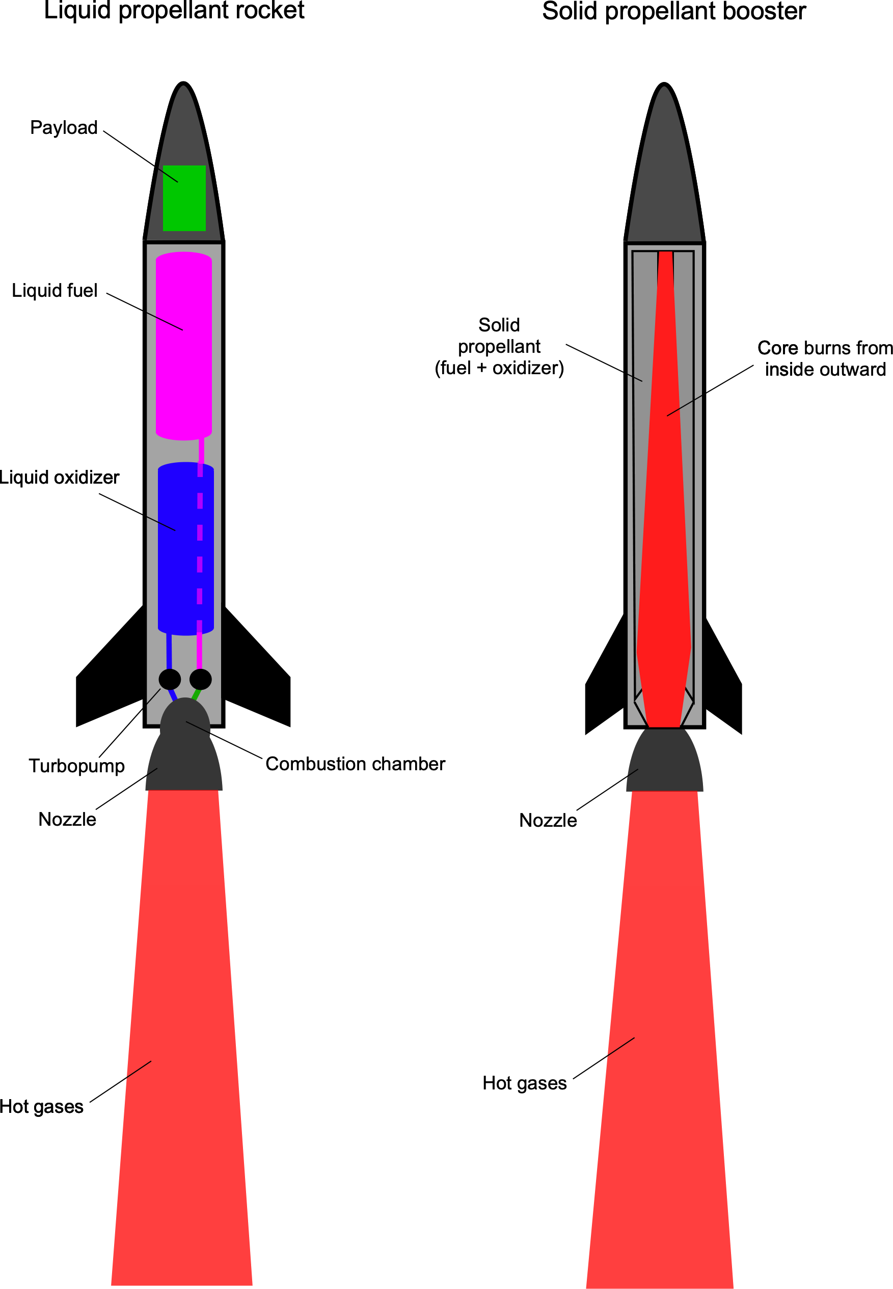
Rocket engines can be broadly categorized by thrust and thrust-to-weight ratio. Rocket propulsion systems are selected according to mission objectives. Generally, there is no one-size-fits-all solution, and multiple rocket propulsion systems can be used for a given space mission. As shown in the figure below, there are two primary types: liquid-propellant rockets and solid-propellant rockets. The latter type is often used as a secondary booster. Another type, the hybrid rocket engine, is considered later.
High-Thrust Propulsion Systems
High-thrust systems are used to overcome gravity, such as in a planetary launch vehicle, or to quickly accelerate a vehicle already in space, such as for an orbital ejection maneuver. These systems store energy in the propellant, allowing it to be converted at a high rate, roughly proportional to the propellant flow rate.
Bipropellant Systems
Bipropellant propulsion systems typically come to mind when considering rocket propulsion; one imagines flames and clouds of smoke, such as during a NASA Space Shuttle or SpaceX Falcon 9 launch. The propellant is the combustion product of a fuel and an oxidizer. Combustion is generally the fastest way to convert chemical energy into kinetic energy. Bipropellant systems are categorized into three main types: gas/liquid propellant systems, solid propellant systems, and hybrid solid fuel/oxidizer systems.
Gas/Liquid Systems
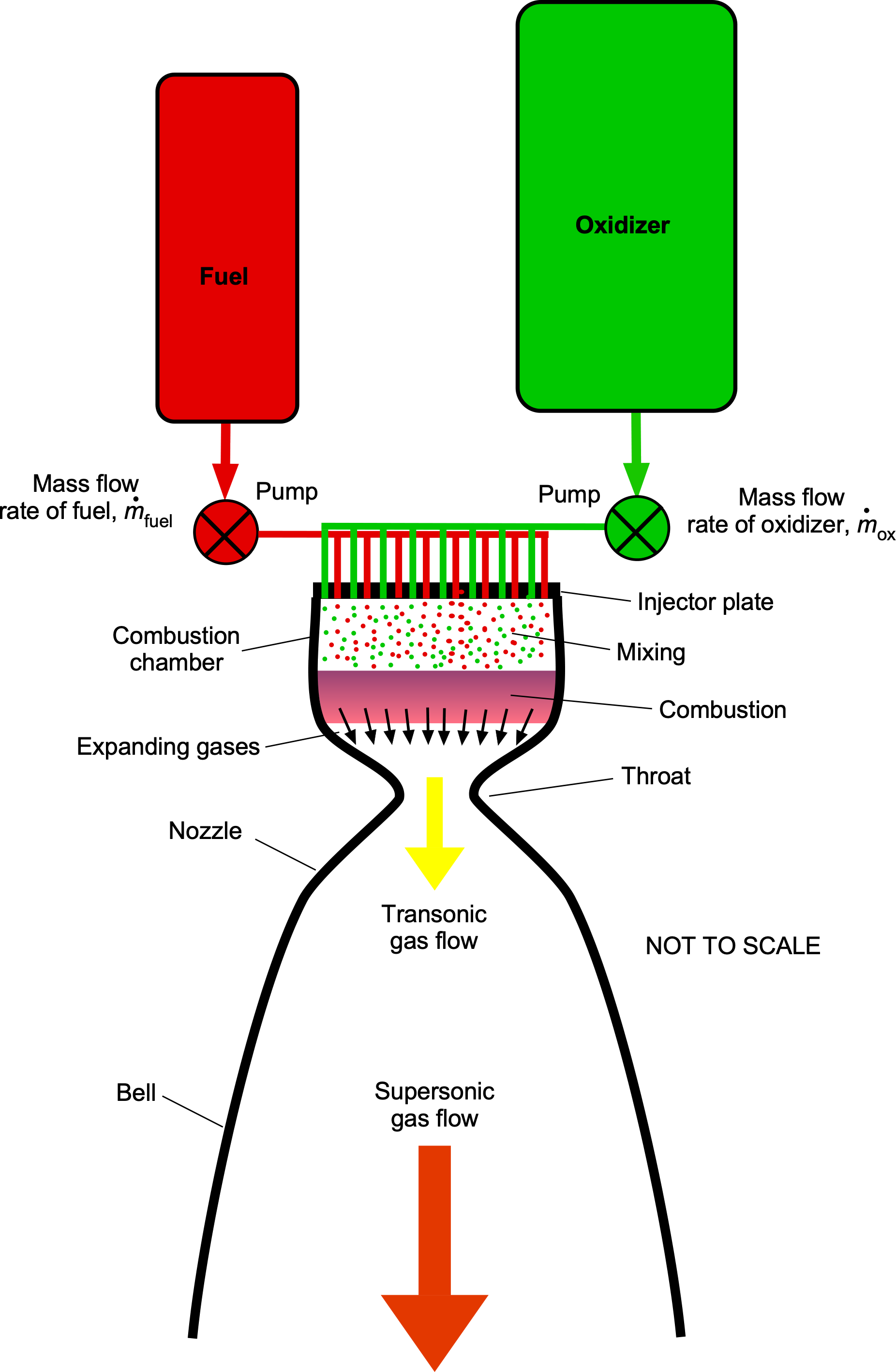
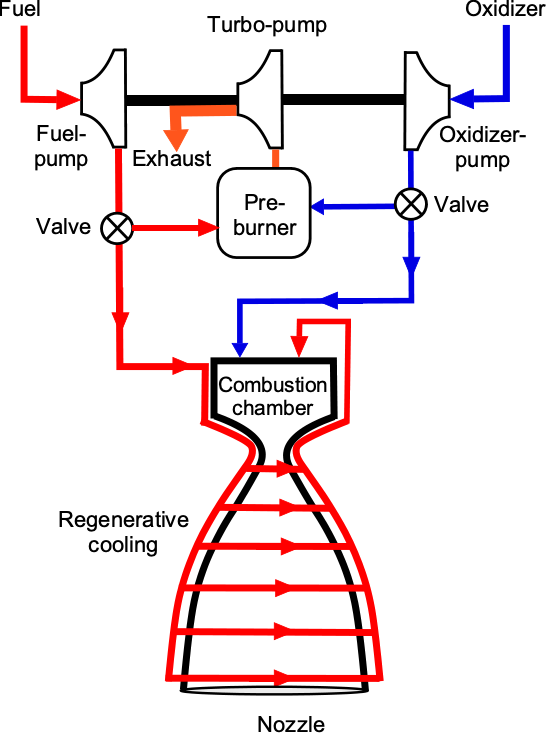
Examples of this type of propulsion system include the Space Shuttle main engine (SSME), which burned liquid hydrogen (LH2) and liquid oxygen (LOX), and the Merlin engine used on the SpaceX Falcon 9, which burns Rocket Propellant-One or RP-1 (a densified kerosene) and LOX, the combination often being called Kerolox. The process of mixing the fuel and oxidizer in the engine is shown in the schematic below. The enormous volume flow rates require turbo-pumps, which are driven by burning a small quantity of fuel and oxidizer tapped off from a bypass circuit.
As shown in the photograph below, a Saturn V rocket launched Apollo 11, the first mission to land humans on the moon, and lifted off from Kennedy Space Center in July 1969. The first stage of the Saturn V rocket used five F-1 engines. These engines burned RP-1 fuel with liquid oxygen (LOX) as the oxidizer. The F-1 engine was the most powerful single-nozzle liquid-fueled rocket engine ever flown. The second stage used five J-2 engines, with propellant consisting of liquid hydrogen (LH ) and liquid oxygen (LOX). The J-2 engine was designed to provide efficient propulsion at higher altitudes and in space. The third stage of the Saturn V rocket used one J-2 engine, which also powered the trans-lunar injection maneuver, setting the spacecraft on a course toward the Moon.
Liquid methane (CH₄) is gaining popularity for use in commercial rocket engines because of its availability, moderate cost, and good performance. It is also far better for the environment than RP-1, which produces many toxic byproducts. One advantage of a gas/liquid system is that the engine can be throttled by regulating the fuel flow. However, this capability comes at a price, including the complexity and associated weight of pumps, valves, pipes, and cryogenic fuel tanks. Hypergolic propellants are those that combust spontaneously upon contact with one another. These propellants are used for in-space applications rather than launch vehicles, partly because their performance is much lower than that of hydrocarbon and LOX or RP-1 and LOX systems. Also, on the one hand, these chemicals tend to be highly toxic. On the other hand, their advantages include reliability, simplicity (as no ignition system is required), and ignition speed. For example, the Apollo lunar lander used hydrazine (NH ) and nitrogen tetroxide (NO), as did the Space Shuttle reaction control system (RCS).
Solid Fuel Systems
Solid-fuel systems are widely used in both space launch vehicles and military applications because of their simplicity, reliability, and rapid response capability. The Space Shuttle solid rocket boosters (SRBs) are a prominent example of the use of solid propellant for orbital launch. Solid propellants are also widely used in military systems, such as air-to-air and surface-to-air missiles, and intercontinental ballistic missiles (ICBMs), where the ability to store a rocket fully fueled for long periods and launch on short notice is critical. Solid-fuel systems require minimal pre-launch preparation and, once ignited, deliver high thrust without complex fueling, pressurization, or ignition sequences.
A typical solid-fuel formulation is a composite material composed of a finely powdered metallic fuel, a chemical oxidizer, and a polymeric binder. Aluminum (Al) powder is the most common fuel component, chosen for its high energy density and high combustion enthalpy.[3] Magnesium (Mg) is sometimes used in specialized applications. The most common oxidizer is ammonium perchlorate (AP), although ammonium nitrate (AN) is occasionally used where lower energy performance or lower sensitivity is acceptable. The binder provides structural integrity to the propellant grain and often serves as an additional fuel source during combustion. Typical binders include hydroxyl-terminated polybutadiene (HTPB) and polybutadiene acrylonitrile (PBAN). The Space Shuttle SRBs employed a propellant mixture of powdered aluminum and AP with PBAN as the binder.
The propellant mixture is cast or extruded into a rigid cylindrical structure known as the propellant grain, which is enclosed within a casing. The internal geometry of the grain is designed to control the surface area exposed to combustion and tailor the thrust-time profile. Standard grain configurations include cylindrical cores, star-shaped cores, or multi-fin geometries that provide controlled burn-surface evolution as the propellant is consumed. Depending on mission requirements, grain designs can achieve neutral, progressive, or regressive thrust profiles.
Ignition is achieved using an internal igniter, typically a small pyrotechnic charge, which initiates combustion at the center of the grain surface. Upon ignition, combustion gases expand and pressurize the casing. The casing is engineered to withstand the high internal pressures generated during combustion and is typically constructed from steel, aluminum alloys, or composite materials to reduce weight. An internal liner is often applied between the propellant and the casing wall to insulate the casing from high temperatures and prevent direct combustion erosion. Hot combustion gases are accelerated through a nozzle located at the aft end of the rocket. The nozzle of a solid-fuel rocket is typically made of heat-resistant materials, often with ablative liners or graphite inserts.
Solid rockets have critical operational characteristics. Once ignited, they cannot be throttled, shut down, or restarted. Combustion continues until the propellant is exhausted. While this limits mission flexibility compared to liquid-fueled systems, solid-fuel rockets offer significant advantages in simplicity, reliability, storage life, and high initial thrust-to-weight ratios.
Hybrid Systems
Hybrid systems utilize a solid fuel and a gaseous or liquid oxidizer, or, rarely, the reverse, as illustrated in the figure below. Experimentalists, amateur rocket builders, and small rocket companies favor hybrids because they are relatively inexpensive and straightforward to construct. Unlike solid propellants, they can also be throttled and turned off and on again.

It is often argued that hybrid systems are safer than solid propellants or liquid systems. However, this is only partially correct, as the rocket’s propellant still comprises the same fuel and oxidizer. Nevertheless, solid fuel is more stable because it is not pre-mixed with an oxidizer, allowing it to be safely stored and have a longer shelf life. Typical oxidizers used in hybrid rockers are gaseous oxygen (O), nitrous oxide (NO), and hydrogen peroxide (HO).
Hybrid rocket engines, however, have not found many applications in commercial space because they have no performance advantage, i.e., they have relatively modest values in terms of thrust-producing efficiency, and designing for optimal performance is tentative and error-prone (i.e., trial and error). A notable exception is SpaceShipOne, which by design uses HTPB and NO.
Experimentalists and amateur rocket builders often use polyvinyl chloride (PVC) or acrylonitrile butadiene styrene (ABS) as a solid fuel because these are readily available at low cost. Nitrous oxide (NO) or “Nitrous” can be used as an oxidizer with several different fuels, and it is popular for use in hybrid rockets. Nitrous oxide is readily available at a modest cost at automotive stores for use in high-performance race car engines, allowing the engine to burn more fuel and produce more power by providing more oxygen during combustion. NO is also used for medical purposes as a mild anesthetic known as “laughing gas.”
Monopropellant Systems
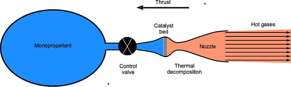
Monopropellants do not burn; they decompose exothermically in the presence of a catalyst. Monopropellant engines generate thrust by propellant flowing through a valve into a catalytic decomposition chamber, where the propellant undergoes a highly energetic decomposition process. The hot gases then accelerate through a nozzle, as shown in the figure below. These thrusters typically provide thrust levels of up to approximately 3,000 N (674 lb).
Hydrogen peroxide (H2O2) is often used for monopropellant engines because it decomposes into water and diatomic oxygen when it comes into contact with many metal oxides, especially silver oxide. An H2O2 system propelled the Apollo lunar lander trainer. However, hydrazine (N2H4) has been used more extensively because of its higher performance and ease of reaction initiation. The rocket engine on the New Horizons spacecraft is an N2H4 monopropellant system.
Cold Gas Thrusters
Cold gas thrusters are rocket engines that use compressed gas, typically nitrogen or helium, as a propellant. They release the pressurized gas through a nozzle to generate thrust, as shown in the figure below. Because they do not involve combustion, cold gas thrusters have a relatively low specific impulse, meaning they provide less thrust per unit of propellant than other rocket engines. Their simplicity makes them less efficient and powerful than monopropellant or bipropellant engines.
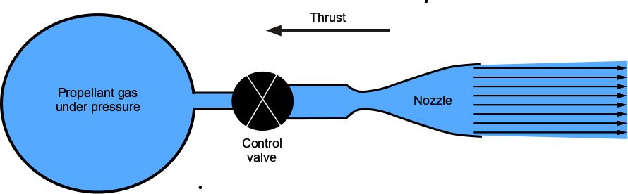
Cold gas thrusters are commonly used for small spacecraft or subsystems that require small, precise movements or adjustments. They are appropriate for CubeSats, nanosats, and small spacecraft attitude control. Any gas can be used as a propellant, but those with lower molecular weights, such as hydrogen (H2), nitrogen (N2), and helium (He), will perform better.
Check Your Understanding #3 – Nitrogen or helium?
You go for an interview with SpaceX. During the interview, they ask you whether nitrogen or helium is better for a cold gas thruster to control the new versions of their StarLink satellites, and why. What is your response?
Show solution/hide solution.
You first explain that helium and nitrogen offer distinct advantages and trade-offs for cold gas thrusters. You write down and demonstrate that the thrust produced by the thruster will be
![\[ T = \overbigdot{m}_p \, V_e \]](https://eaglepubs.erau.edu/app/uploads/quicklatex/quicklatex.com-43deca67779b72c50303c8809678c7ef_l3.svg "Rendered by QuickLaTeX.com")
where  is the mass flow rate, and
  is the exhaust (exit) velocity. Therefore, for a given propellant mass flow rate, the thrust produced will be related to the achievable exhaust velocities, but every AE graduate knows that, so you are not ahead of the game.
However, they begin to get impressed when you go on to say that the best propellants are those with low molecular mass, which give higher values of specific impulse. To compare the potential exhaust velocities of two gases, the exhaust rate of a gas at a constant temperature will be inversely proportional to the square root of its relative molecular mass, i.e., in this case
![\[ \frac{\text{\small Flow rate of He}}{\text{\small Flow rate of N}_2} = \sqrt{ \frac{M_{r_{\text{N}_2}}}{M_{r_{\text{He}}}} } \]](https://eaglepubs.erau.edu/app/uploads/quicklatex/quicklatex.com-f5280c764229db83152400d4e9d2d9ae_l3.svg "Rendered by QuickLaTeX.com")
where is the relative molecular mass of the gas. Fortunately, you recall from your chemistry classes that helium ( ) has a relative molecular mass of approximately 4, and nitrogen (
 ) has a relative molecular mass of approximately 28. Therefore, you write down that
![\[ \frac{\text{\small Flow rate of He}}{\text{\small Flow rate of N}_2} = \sqrt{\frac{28}{4}} = \sqrt{7} \approx 2.65 \]](https://eaglepubs.erau.edu/app/uploads/quicklatex/quicklatex.com-2e5198a528baa0216f94c328e0dbff4e_l3.svg "Rendered by QuickLaTeX.com")
You then explain that this result indicates helium will exhaust at approximately 2.65 times the speed of nitrogen because of its lower relative molecular mass. Therefore, using helium will produce 2.65 times as much thrust for a given mass flow rate.
But you are not done! You explain that on the one hand, for the same total mass of propellant,  , helium will require seven times the volume of nitrogen at the same pressure and temperature. On the other hand, seven times less mass of helium needs to be carried to obtain the same total impulse from the thruster, i.e., to get the same values of
  , where
![\[ I = M_P \, V_{\rm eq} \]](https://eaglepubs.erau.edu/app/uploads/quicklatex/quicklatex.com-8d408cca44ae9c14556c7e7a529b7cb6_l3.svg "Rendered by QuickLaTeX.com")
To clinch the job, you finally explain that helium is more expensive and requires careful thermal management. In contrast, nitrogen is much cheaper, more readily available, and easier to handle. Therefore, nitrogen gas is often chosen for thrusters with moderate performance requirements. Ultimately, you say the choice between the two gases will be mission-specific, balancing performance and cost.
Congratulations!
High-Efficiency Propulsion Systems
In high-efficiency systems, the energy is not stored in the propellant but is generated by an onboard system. Therefore, the energy conversion rate is not proportional to the propellant flow rate; instead, it is limited by the power supply system’s capability. For example, solar panels or a nuclear source can generate electrical or thermal power. Considering the energy supply rate (power) to the propellant to be fixed, a lower propellant flow rate will result in higher efficiency but lower thrust, which is insufficient for use as a launch vehicle. High-efficiency systems are then used for long-duration missions to deep space or to raise the orbits of satellites.
In each case, this propulsion system does not have to oppose gravity directly (that is, to “lift” the spacecraft). However, it increases its velocity gradually once the spacecraft is in space. The simplest system heats the propellant gas, which then expands rapidly through a nozzle. A solar thermal system collects and focuses sunlight onto the propellant flow path. A thermal-electric system heats the gas using a resistive element or an electric arc. In other systems, electrical power is used to ionize the propellant gas, producing an electric and/or magnetic field, after which the charged particles are accelerated. Several configurations exist for such systems, including ion thrusters, Hall effect thrusters, and magnetoplasmadynamic thrusters.
Electric rocket engines, such as ion thrusters or Hall effect thrusters, are becoming increasingly attractive for use on spacecraft. These engines cannot produce much thrust but are highly efficient, maintaining thrust for extended periods, making them well-suited for deep-space missions.
Total Impulse & Specific Impulse
Establishing a rocket engine’s thrust and efficiency characteristics requires some quantitative performance measures. The total impulse is defined as the integral of the thrust over its burnout time, i.e., the time the engine operates. The measure of efficiency used in most rocket performance calculations is the specific impulse, which is the thrust divided by the propellant flow rate. Generally, the goal is to carry as little propellant as possible. The specific impulse is a property of the propellant’s chemical composition and can be evaluated through a thermodynamic analysis.
Impulse
The impulse is given by
(15) 
If and are constant, as is often a good approximation, then
(16) 
where is the mass of the propellant used. The total impulse, therefore, will be equivalent to the net momentum imparted to a rocket during the engine burn.
Specific Impulse
The specific impulse,  , is
, is
(17) 
where  is the acceleration under gravity at sea level on Earth, which is used as a reference. Therefore, the higher the value, the more efficiently the rocket engine will produce thrust. It is further apparent using Eq. 5 that
(18) 
where it will be noticed that is measured in units of time (seconds). Therefore, the specific impulse is the total impulse (or change in momentum delivered) per unit weight of the propellant consumed. The value is dimensionally equivalent to the generated thrust divided by the propellant flow rate, expressed as fuel weight per unit of time. So, in some ways, it is equivalent to the inverse of the thrust-specific fuel consumption used by a jet engine.
Standard Gravity
The standard acceleration under gravity or “standard gravity,” denoted by , is the nominal gravitational acceleration of an object at the surface of the Earth. The value of is defined as 9.81 m/s or 32.17 ft/s. The symbol “
 ” should not be confused with “
 ” for the universal gravitational constant or “g” (non-italicized) used as the symbol for the gram.
Notice that if mass (in slugs or kilograms) is used as the unit of propellant, then the specific impulse has units of velocity. If weight (lb or N) is used, which is much more common, the specific impulse is measured in units of time, typically seconds. Notice that these two definitions differ by a factor of . The higher the specific impulse, the less propellant is needed to produce a given thrust during a given time. Some propellants and their specific impulse values are shown in the table below. While it can be seen that H2/O2 (LH2/LOX) has the highest specific impulse, liquid hydrogen needs a much larger (volumetric) fuel tank than RP-1, and it is also more expensive and challenging to transport and store. Liquified methane is fast becoming the rocket fuel of choice, but it must be stored cryogenically, so it is subject to the same issues as liquid hydrogen (LH2).
| Propellant | Molecular weights | Specific Impulse (secs.) |
|---|---|---|
| H2/O2 (LH2/LOX) | 2/32 | 445 |
| RP-1/O2 (Kerosine/LOX) or Kerolox | 170/32 | 295 |
| H2O2 (Hydrogen Peroxide) | 34 | 300 |
| CH4/O2 (Methane/LOX) or Metholox | 16/32 | 320 |
Thrust or Specific Impulse?
Remember that thrust is a force supplied by the rocket engine, and its value will depend on the amount of propellant flowing through the engine. To this end, the impulse gives a measure of the integrated thrust applied over time. Specific impulse is not a force because its value measures the impulse or momentum produced per unit of propellant and will be proportional to the exhaust velocity. Both metrics help characterize the performance of rocket engines.
Thermodynamic Considerations
Rockets use combustion or chemical reactions to generate hot gases at very high temperatures. These gases are then expanded through a supersonic nozzle to achieve high exhaust-stream velocities. Rocket engines typically operate at combustion temperatures between 2,500 K and 3,500 K, and even then, only because regenerative cooling protects the combustion chamber and nozzle walls from melting under the extreme thermal loads.
The specific impulse can also be related directly to the thermodynamic properties of the combustion gases. From Eq. 7, the specific impulse is given by
(19) 
where  is the absolute combustion temperature, is the molecular weight of the exhaust gas in kilograms per kilomole, is the combustion chamber pressure, and is the exhaust exit pressure.
Equations 8 and 19 show that achieving a high equivalent exhaust velocity and a high specific impulse requires maximizing the combustion temperature and minimizing the molecular weight of the exhaust products. The effect of the specific heat ratio on specific impulse is comparatively less significant than the effects of the combustion temperature and the mean molecular weight of the propellant gases.
To this end, the best-performing chemical propellant combination is liquid hydrogen (LH) and liquid oxygen (LOX). Liquid hydrogen has a relative molecular weight of  , and liquid oxygen has
  ; when combusted together, they produce superheated steam (HO) with a molecular weight of approximately
  . For cold gas thrusters, inert gases such as helium and nitrogen are commonly used. Helium, with
  , and nitrogen, with
  , are both effective choices, although helium is preferred for its low molecular weight despite its lower availability and relatively high cost.
Check Your Understanding #4 – Using specific impulse to calculate thrust
A rocket engine is to be tested on a test stand. The burning of the propellant occurs at a steady rate of 150.0 kg/s, and the specific impulse of the propulsion system is 240.0 seconds. What thrust does the rocket engine develop?
Show solution/hide solution.
The equivalent exhaust velocity is given in terms of the specific impulse, i.e.,
![\[ V_{\rm eq} = I_{\rm sp} \, g = 240.0 \times 9.81 = 2,354.4~\mbox{m/s} \]](https://eaglepubs.erau.edu/app/uploads/quicklatex/quicklatex.com-cd52731a2d2284c5e85ef183ad1bf062_l3.svg "Rendered by QuickLaTeX.com")
Therefore, the thrust produced will be
![\[ T = \overbigdot{m}_P \, V_{\rm eq} = 150.0 \times 2,354.4 = 353.16~\mbox{kN} \]](https://eaglepubs.erau.edu/app/uploads/quicklatex/quicklatex.com-13698e0680f191dd986f4ecf5c571afd_l3.svg "Rendered by QuickLaTeX.com")
More About Specific Impulse
In SI units, thrust is measured in Newtons (N), and mass flow rate is measured in kilograms per second (kg/s). In USC units, thrust is measured in pounds (lb), a unit of force. Propellant flow rate is sometimes incorrectly reported in pounds mass per second (lb/s), but strictly speaking, it should be expressed in slugs per second (slug/s) to maintain dimensional consistency. However, by convention, specific impulse in USC units is defined as thrust divided by the propellant’s weight flow rate, allowing  to retain units of seconds without explicitly converting mass to slugs.
There are two ways to interpret the apparent discrepancy in USC units. Strictly, mass should be expressed in slugs, recognizing that 1 slug mass  32.17 lb of weight. Alternatively, by convention, is viewed as thrust divided by the weight flow rate, meaning the use of pounds per pound-per-second without adjusting for . In either case, specific impulse expressed in seconds provides a convenient normalized measure of exhaust velocity. Recall that the effective exhaust velocity is related to specific impulse by
(20) 
where is the effective exhaust velocity. If the fundamental thrust equation
(21) 
is used, then it follows that
(22) 
Specific impulse, therefore, provides a direct link between the thrust produced and the velocity at which propellant is expelled, scaled by gravitational acceleration to ensure consistent units in both SI and USC systems.
Altitude Dependence on Specific Impulse
A rocket engine’s specific impulse, , varies with altitude because of changing ambient pressure. As a rocket ascends, the surrounding pressure  decreases, which alters the thrust produced and hence affects the specific impulse. The thrust produced by a rocket is given by the momentum equation, i.e.,
(23) 
where is the propellant mass flow rate, is the exhaust velocity at the nozzle exit, is the static pressure at the nozzle exit,  is the local ambient pressure, and is the nozzle exit area. The second term represents the pressure thrust contribution, which increases as decreases.
Recall that the specific impulse is defined as
(24) 
where is the standard gravitational acceleration. Substituting the expression for thrust gives the altitude-dependent form of the specific impulse, i.e.,
(25) 
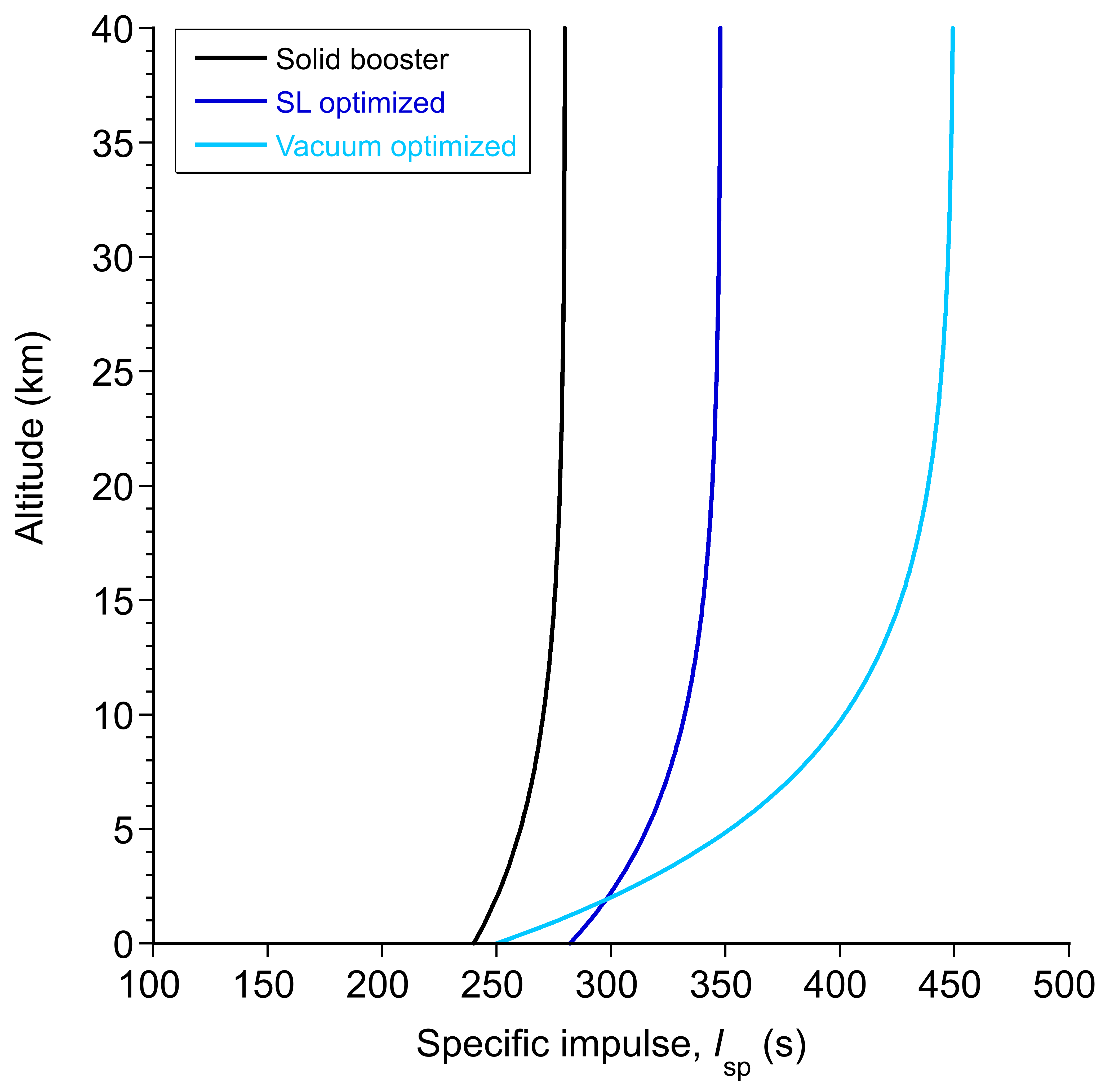
As the altitude increases and  decreases toward zero, the pressure thrust increases and so does , as shown in the figure below. Notice the much lower value of for the vacuum optimized engine at sea level, but this quickly changes at higher altitudes.
 with altitude reflects the role of ambient pressure in opposing the exhaust jet.
This outcome leads to two commonly cited values for specific impulse:  at sea level, and
  in vacuum. The difference between them can be substantial, especially for engines with large nozzle expansion ratios. For example, a Merlin engine optimized for sea level operation has
  282 s at sea level and 348 s in a vacuum. A vacuum-optimized engine such as the RL10 has 250 s at sea level and 450 s in a vacuum.
| Engine Type | Isp (Sea Level) (s) | Isp (Vacuum) (s) |
|---|---|---|
| Solid Rocket Booster | 240 | 280 |
| Liquid Engine (Merlin) | 282 | 348 |
| Vacuum Engine (RL10) | 250 | 450 |
| Hypergolic Engine (AJ10) | 290 | 319 |
| Methalox Engine (Raptor) | 330 | 380 |
| Ion Thruster (NSTAR) | — | 3100 |
| Nuclear Thermal Rocket (NERVA) | — | 850 |
The increasing trend of with altitude reflects the role of ambient pressure in opposing the exhaust jet. Vacuum-optimized nozzles are typically underexpanded at low altitudes and reach optimal performance only in near-vacuum conditions. This nozzle design tradeoff is a key constraint in staging and mission architecture.
More About Solid-Fuel Rockets
With solid-fuel rockets, the thrust produced is not determined solely by the chemical composition of the propellant. Still, it is also critically influenced by the geometry and evolution of the burning surface, often referred to as the conflagration surface surface. The surface area available for combustion directly controls the rate at which the propellant mass is consumed. The instantaneous mass flow rate of combustion gases, , is proportional to the burning surface area,  , and the regression rate,
  , of the propellant, which can be expressed as
(26) 
where  is the density of the solid propellant, is the instantaneous burning surface area, and is the linear burn rate. The thrust generated by the rocket engine is then determined by the exhaust mass flow rate and the effective exhaust velocity
  according to the standard thrust (momentum) equation, i.e.,
  . Therefore, an increase in burning surface area results in a higher mass flow rate and, therefore, a higher thrust.
In practical solid rocket engine design, the internal geometry of the propellant grain is shaped to control the burning surface area over the course of combustion. The grain geometry determines whether the burning area remains approximately constant, increases, or decreases during the burn, thereby producing thrust profiles described as neutral, progressive, or regressive, respectively. For example, a grain designed for a neutral burn maintains nearly constant thrust over time, whereas a progressive burn profile results in increasing thrust as the surface area grows.
A simple circular bore grain produces a progressive-regressive thrust curve, as shown in the figure below. The thrust quickly increases and remains relatively constant as the surface area grows, but it eventually decreases as the burning surface area reduces near the end of the burn. An end-burner grain is characterized by a propellant that burns from one axial end face to the other. This configuration produces a steady, long-duration burn. However, end-burners pose thermal management challenges because the burning face remains stationary along the axis, leading to prolonged heating of the structure. Additionally, significant shifts in the center of gravity occur during the burn as the mass moves steadily toward the nozzle end, potentially complicating the launch vehicle’s stability and thrust vectoring response.

The C-slot grain features a wedge cut out along the axial direction of the propellant. This design produces a relatively long regressive thrust profile, where the thrust decreases over time as the burning surface area diminishes. However, C-slot grains also experience thermal issues due to localized heating and an asymmetric center of gravity. The main advantage of an off-center circular bore is that it produces a progressive-regressive long-duration burn profile, allowing the overall thrust history to be tailored for favorable long-duration performance.
The finocyl grain, typically designed with a five- or six-pointed star-like structure, combines characteristics of a cylindrical bore with added internal fins. This configuration produces a relatively level thrust profile, with a somewhat quicker burn than a pure circular-bore design due to the increased initial burning surface area provided by the fins. Finocyl grains are often used when a balance between high thrust, efficient burning, and moderate burn duration is required.
Finally, it should be recognized that the burn rate itself is also dependent on the local chamber pressure and the propellant chemistry, typically following an empirical relationship of the form
(27) 
where  is a burn rate coefficient that is dependent on the specific propellant formulation,
  is the local combustion chamber pressure, and
  is a semi-empirical exponent, usually ranging between 0.2 and 0.5 for most solid propellants. Therefore, the conflagration surface area, the regression rate, and the feedback between burning rate and chamber pressure collectively determine the thrust history of a solid rocket booster. The conclusion from the foregoing is that careful control of grain geometry and propellant characteristics is essential to achieve the desired thrust profile during flight.
Summary & Closure
Gas- or liquid-fuel rocket engines have been employed for many spaceflight applications, including most launch vehicles. Such systems are efficient and have the advantage that the engine can be throttled by regulating the fuel flow, e.g., to limit dynamic pressure loads on the vehicle during its launch. However, this capability comes at a price, including mechanical complexity and associated weight. For some launch vehicles, the thrust from the liquid-fuel engines is augmented by solid rocket boosters, which can provide more than half of the initial thrust at liftoff, as in the Space Shuttle. Solid fuel engines are also used on missiles and for other in-space applications. The lower performance and non-throttling characteristics of solid propellant engines are acceptable because of their operational simplicity, even though solid rocket boosters are by no means simple propulsion systems.
Since the dawn of human space flight in the 1960s, advancements have continued to be made using improved propellants and rocket engine designs. Today, most space missions use a combination of engines and fuels, selected to optimize the thrust required at each mission stage, including launch and in space. Rocket engines produce extremely high thrusts and operate near their safe limits, albeit for relatively short times. However, the reliability of rocket engines is still a concern, especially when they are recovered and reused to save on launch costs. In addition, the environmental compatibility of rocket fuels has become a more significant concern in recent years, and the move toward alternative propellants, such as methane, will continue.
5-Question Self-Assessment Quickquiz
For Further Thought or Discussion
- Discuss and identify safety hazards associated with liquid, solid, and hybrid rocket propulsion systems.
- What type of fuel is used for the SpaceX Raptor engine? What are the advantages of this type of fuel?
- Research high-specific impulse propulsion systems. What values for specific impulse are attainable?
- What types of thrusters are used for cubesats, nanosats, and small spacecraft attitude control?
Other Useful Online Resources
To learn more about rocket propulsion, check out these helpful online resources:
- A series of videos on how rocket engines work: The playlist is here.
- A good video on how rockets work.
- An article on the history of rockets by NASA.
- A simple guide on how rockets work by NASA.
- A fantastic explanation of the Saturn 5 rocket.
- Learn more about solid fuel rockets from Northrop-Grumman.
- Some good resources on solid fuel rockets by AeroJet-RocketDyne.
- The Smithsonian Air and Space Museum entry on the X-15 a rocket-powered aircraft.
- An article from AIAA: X-15 Propulsion System
- Elon Musk explains how the Raptor 2 rocket engine works.
- A video on how to start up a rocket engine!
- Prof. Eric "Rick" Perrell wrote the initial draft of this chapter. His expertise, knowledge, and contributions to this eBook on rockets are greatly appreciated. ↵
- Notice that in the technical literature, the universal gas constant is sometimes interchanged with the specific gas constant for a particular gas. The specific gas constant is related to the universal gas constant by
 where applies to a specific gas species of relative molar mass . In contrast, is the universal gas constant applicable to any ideal gas. ↵
 - Combustion enthalpy, which represents the total thermal energy released per unit mass of propellant during combustion, directly influences the amount of energy available to be converted into the kinetic energy of the exhaust gases. ↵

.jpg)