66 Autogiros & Gyroplanes
Introduction[1]
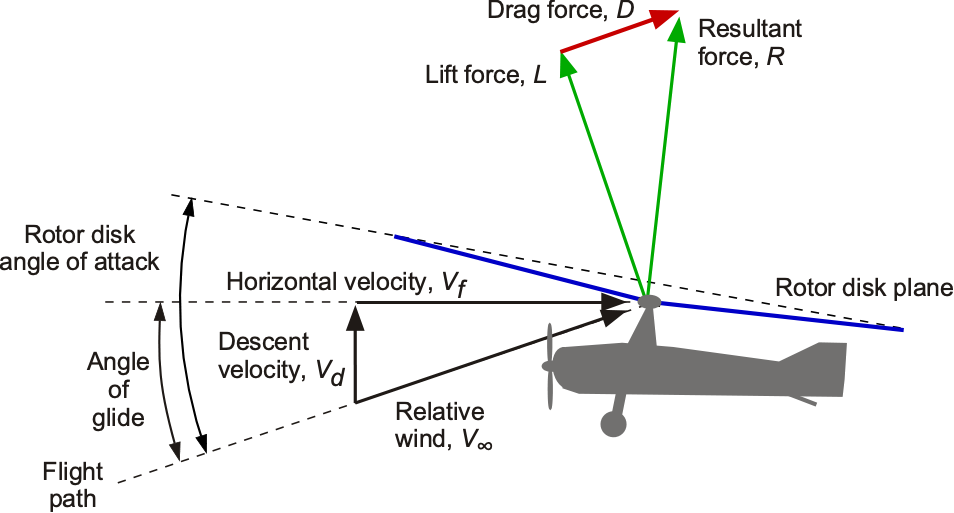
An autogiro, also known as a gyroplane, features freely rotating rotor blades attached to a shaft. Unlike a helicopter, however, its rotor is not driven through its shaft. Instead, it relies on a phenomenon called autorotation, where the rotor spins naturally and is lifted by the aerodynamic forces produced on the blades. As the aircraft moves forward, powered by a conventional engine and propeller, the airflow interacts with the rotor, which is tilted backward relative to the airflow (nose-up relative to the airspeed vector), as shown in the figure below. This interaction generates lift on the spinning blades, allowing the autogiro to stay aloft while maintaining controlled flight. As long as forward motion and/or descent are constantly maintained, the rotor will continue to autorotate and generate lift.
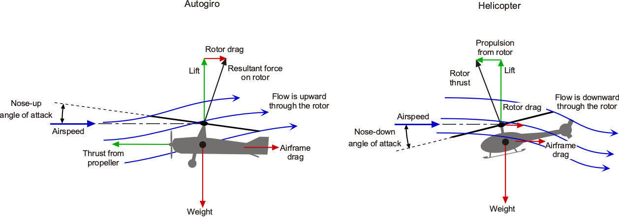
While the autorotating rotor provides lift, it also gives control because the pilot can tilt the rotor disk plane using some control system, such as a tilting shaft or swashplate mechanism. The autogiro obtains its forward propulsion from a conventional tractor or pusher propeller, a pusher design being preferred due to the significantly improved visibility it provides to the pilot, comparable to that of a helicopter. In contrast, a helicopter’s rotor provides three intrinsically combined functions: lift, forward propulsion, and control. If an autogiro also features a fixed wing or can hover (such as using reaction-drive rotors, including tip jets), but still operates as an autogiro in forward flight. In that case, it may be referred to as a convertiplane or gyrodyne.
Autorotation can be seen naturally in the flight of maple and sycamore seeds.[2] However, the somewhat curious aerodynamic phenomenon of “autorotating bodies” had already been documented in the scientific literature by the early twentieth century, likely influenced by the theoretical work of Scottish physicist James Clerk Maxwell.[3] Around 1910, Gaetano Crocco and Boris Yuriev separately studied the principle of autorotation as it affected spinning rotors. Later, Max Munk[4] conducted experiments with “helicopter propellers,” encountering the “parachute effect,” again demonstrating the phenomenon of autorotation.
In 1923, a new aircraft type, soon to become known as the Autogiro, became the first successful rotating-wing airplane to fly. It used the principle of autorotation and was the first powered, heavier-than-air aircraft to achieve flight other than a conventional airplane. Conceived by Juan de la Cierva around 1920, following tests made using free-flying models and wind tunnel experiments, more than thirty Cierva Autogiro variants were developed between 1923 and 1938. The name “Autogiro” was trademarked by Cierva and should always be capitalized when referring to his designs. De la Cierva proved that his Autogiros were safe and could operate from short airfields thanks to their low-speed flight capability. Even by the late 1920s, Cierva’s Autogiros demonstrated a potentially valuable future role in aviation.
Although the autogiro’s role in aviation during the 1920s to the 1940s was soon to be replaced by helicopters, its technological innovations directly influenced the development of helicopters and shaped modern rotary-wing aviation. Today, autogiros remain more of a niche interest, perhaps an aeronautical curiosity. While they offer advantages such as very slow-speed flight, short takeoff and landing capabilities, and docile flight characteristics, they have not gained widespread adoption because they cannot hover. Additionally, the aviation industry has heavily invested in airplane and helicopter technology to meet commercial and military transportation requirements, leaving autogiros with limited roles. While the most recent developments with autogiros and gyroplanes have been primarily for sport aviation, the emergence of unpiloted aerial systems and personal air mobility developments may still revive future interest in autorotating flight vehicles.
Learning Objectives
- Learn about the history of autogiros and gyroplanes and how they helped shape the development of rotating-wing aviation.
- Understand the principles of autorotation and how autogiros generate lift without the need for engine-driven rotors.
- Appreciate the performance differences between autogiros and helicopters, and why helicopters eclipsed their flight capabilities.
- Consider why the future development of autogiros and gyroplanes may still help expand the scope of aviation.
History
In 1910 or thereabouts, Boris Yuriev found that, under certain conditions, such as in steeply descending or horizontal flight with the rotor disk set at a positive angle of attack, a lifting rotor could turn of its own accord.[5] Yuriev referred to this effect as “rotor gliding,” and he appears to have recognized even then that this self-rotating capability could potentially be used to land a helicopter safely in the event of an engine failure. Today, a flight maneuver called an autorotational landing remains a fundamental safety feature in helicopters, enabling controlled flight to the ground in emergencies such as power or tail rotor failure.
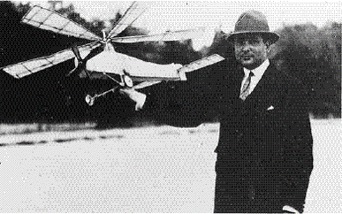
In 1920, a young Spanish engineer, Juan de la Cierva, built small, unpowered, free-flying models of a new type of rotating-wing aircraft. The rotor blades, mounted on a vertical shaft, were free to spin. His vision was for an aircraft where “stability, uplift, and control should remain independent from forward speed” and one that a pilot of average skill could fly safely. His models were launched from a balcony on his house and demonstrated self-sustaining flight, gliding softly to the ground. In doing so, Cierva rediscovered the principle of autorotation and soon developed a new type of airplane, which he named the Autogiro.
While Cierva was not the first to observe or describe autorotation, he was the first to systematically study its aerodynamic principles and harness them for practical aviation. He conducted some of the earliest theoretical analyses of rotors[6] and performed a series of wind tunnel tests. Cierva’s first piloted Autogiro, the C.1, was built in 1920 and featured a coaxial rotor design; his motivation was that the two counter-rotating rotors would balance out the aerodynamic differences between the advancing and retreating blades, thereby addressing the problem of dissymmetry of lift. However, when flight tests began, it was found that the aerodynamic interference between the rotors resulted in different autorotational rotor speeds, causing the machine to roll over and crash.
Cierva was then to build two more machines, both with single rotors. The C.2 and C.3 were only to achieve short hops off the ground before rolling and crashing. The C.2 had a rigid rotor, with roll control achieved through differential elevator inputs. The C.3 employed a form of blade twisting to attempt to balance the dissymmetry in lift. After numerous attempts and numerous crashes, he achieved final success with C.4, as shown in the figure below. This machine incorporated mechanical hinges, essentially pin joints, allowing the blades to flap freely up and down in response to changing lift forces as they rotated.
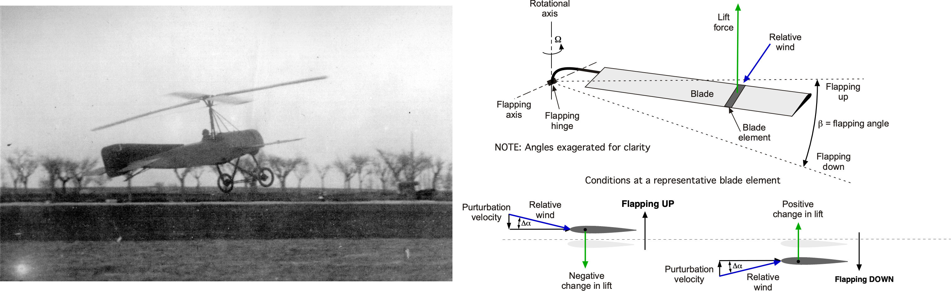
As the blades flapped down, their lift increased, providing a restoring force upward. Likewise, as the blade flapped up, their lift decreased, also providing a restoring force. The net effect was that the flapping hinge allowed the lift distribution to be more balanced across the rotor disk in forward flight, with the additional advantage of eliminating adverse gyroscopic moments on the rotor shaft. To control flapping angles and prevent the blades from drooping to the ground when stationary, they were restrained by cables, known as “guy wires.”
Further developments were rapid after the first successful flight of the C.4. Cierva’s work continued in Britain with the financial support of the Weir Company of Glasgow. By 1926, the C.6 had been demonstrated to the British Air Ministry, and soon, the Cierva Autogiro Co. Ltd. was formed. Thereafter, Cierva’s Autogiro designs were built in Britain, mainly by the A.V. Roe (Avro) company. In 1928, the Cierva C.8 flew across the English Channel, proving the autogiro’s range capabilities and reliability. In the early 1930s, autogiros also saw limited commercial use, with the Pitcairn PCA-2 becoming the first certified rotating-wing aircraft in the U.S.
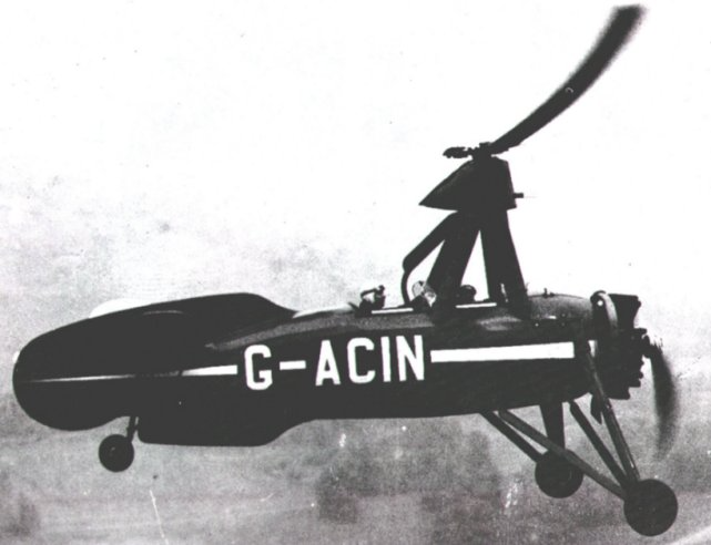
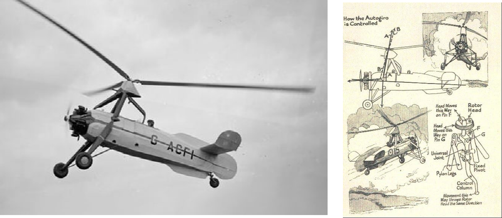
Cierva’s C.30 model of 1933 provided the pilot with direct control of the rotor, allowing for lateral and longitudinal tilting of the rotor disk from a “hanging stick,” as shown in the photograph below, which significantly improved the autogiro’s handling qualities. Around the same time, military forces in Britain, Germany, and the U.S. explored using autogiros for reconnaissance, artillery spotting, coastal patrol, and covert operations behind enemy lines, exploiting their slow speed and short takeoff and landing capabilities. Using the kinetic energy in the blades, almost vertically controlled landings were possible, rivaling what was to become possible with future helicopters.
The rapid development of the autogiro during the 1920s and 1930s spurred early scientific research on rotating-wing aerodynamics by Hermann Glauert and Christopher Lock, whose theoretical studies were supported by wind tunnel experiments.[7] In 1926, Glauert published a seminal paper[8] on induced inflow and rotor performance, providing foundational equations for explaining the principles of rotating-wing aerodynamics. Cierva contested these theories,[9] who claimed they were inconsistent with his flight tests of the C.6. Nevertheless, Glauert’s theories and methods have shown good validity and stood the test of time.
The development of “jump” and “towering” takeoff techniques was accomplished by overspeeding the rotor on the ground, abruptly increasing blade pitch, quickly powering up the engine, and then accelerating into autorotative forward flight. This capability brought the autogiro’s capabilities closer to those of the helicopter in terms of flight performance. The C.40 was the last Autogiro produced by the Cierva Autogiro Company and represented the pinnacle of its technology. However, a limitation of the autogiro is that it could not hover, and hover capability soon became the overarching performance requirement for a rotating-wing aircraft. By the 1940s, the rapid advancements in helicopters, particularly in Germany and the U.S., which were primarily based on the engineering innovations for rotor systems developed by Cierva and Pitcairn, soon overshadowed any further developments of the autogiro.
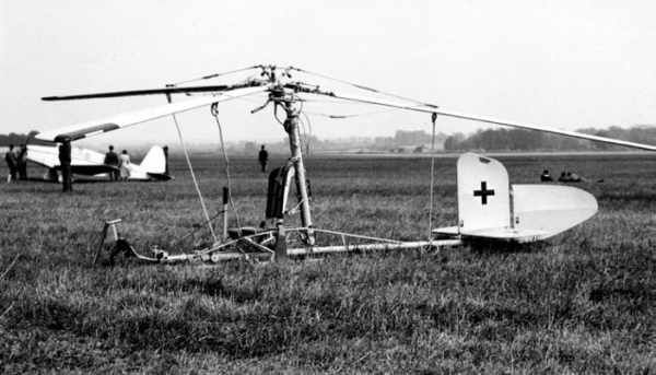
Nevertheless, further developments continued, and during WWII, Germany deployed the Focke-Achgelis Fa 330, a rotor kite towed behind a submarine; the machine is shown in the photograph below. Focke-Wulf constructed Cierva’s C.19 and C.30 Autogiros under license from 1930 until after Juan de la Cierva was killed in 1936, but they saw limited use. Hanna Reitsch demonstrated the Focke-Wulf Fw 61 helicopter in Berlin in 1938, the rotors derived from Cierva’s autogiro designs. Elements of Cierva’s rotor technology were used, leading some to argue that the Fw 61’s design was inadequately appropriated. Nevertheless, it was clear that the helicopter had reached the tipping point of success.
By the late 1940s, helicopters like the Sikorsky R-4, R-5, and R-6, as well as the Bell 47 and Bristol 171 Sycamore, had rendered autogiros quickly becoming obsolete in mainstream aviation. However, several other factors contributed to the decline of the autogiro in the 1940s. Military interest in helicopters grew in the U.S., spurred by the 1938 Dorsey-Logan Bill, which provided funding for rotary-wing research. This led to the Rotating-Wing Aircraft Conference at The Franklin Institute in Philadelphia in 1939, bringing together leading engineers such as Raoul Hafner, Harold Pitcairn, and Igor Sikorsky. At this conference, Igor Sikorsky, who was actively developing the VS-300, presented a paper outlining the helicopter’s potential. The imminent success of the VS-300, coupled with Dorsey-Logan Bill funding and the rapid pace of wartime aeronautical innovation, shifted attention decisively toward the development of helicopters. As a result, further work on autogiros was slowed or stopped, the aircraft being sidelined despite its foundational contributions to helicopter technology.
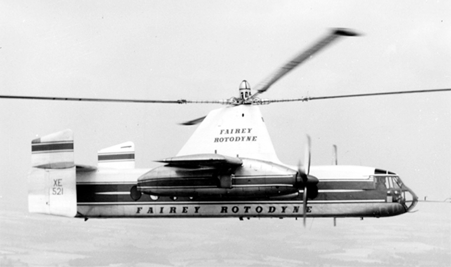
In the 1950s, interest in autogiros, gyroplanes, and convertiplanes experienced a modest revival, resulting in prototype machines from Fairey Aviation in Britain and McDonnell Aircraft in the United States. These designs sought to overcome the forward speed limitations of helicopters by offloading rotor thrust requirements through the use of a fixed wing. Gyroplanes can take off vertically and hover when the rotor is powered by tip jets; however, these are switched off in forward flight, allowing the rotor to transition into full autorotation. McDonnell developed the XV-1, but its performance was disappointing, and it was canceled. Fairey Aviation’s Gyrodyne prototypes led to the Rotodyne, the world’s largest gyroplane, capable of carrying 40 passengers. Using tip jets for takeoff and landing, the Rotodyne was a technical success. It set a world speed record for convertiplanes in 1959 before its cancellation in 1962. In hindsight, it was likely not the technical capabilities of the Rotodyne that failed, but rather the lack of infrastructure, regulatory clarity, and commercial readiness that ultimately rendered the project unsustainable.
During the late 1950s and early 1960s, several autogiro designs emerged for use in general aviation, produced by Umbaugh (later Air & Space) and McCulloch. However, limited flight performance and weak sales forced the companies out of business. In Britain, single- and two-seat autogiros were built by Igor Bensen, inspired by the German Fa-330 “Kite” and Hafner’s “Rotachute,” which created a thriving amateur market that remains active today, with many current designs tracing their roots back to Bensen’s concepts. Among the most iconic derivatives were the machines flown by Ken Wallis, whose highly refined, minimalist gyrocopters gained fame when he piloted “Little Nellie” in the 1967 James Bond film You Only Live Twice. As of 2025, several manufacturers serve this gyrocopter market, and the Popular Rotorcraft Association maintains a current listing of autogiros and gyroplanes.
In the 1990s, two U.S. companies began developing lightweight autogiros: Carter Aviation Technologies (now Jaunt Air Mobility) and Groen Brothers Aviation (now Skyworks Aeronautics), utilizing modern advancements in aerodynamics, materials, and flight controls. Carter’s prototype combined a slowed autorotating rotor with a high aspect ratio fixed wing; the derivative by Jaunt Air Mobility is a similar concept. GBA’s Hawk 4 prototype was a turboprop-powered autogiro with a demonstrated level-flight speed of 148 mph (238 kph). It showed impressive short takeoff and near-vertical landing capabilities. The two-bladed articulated rotor incorporated a cone-pitch coupling for rotor speed stability and a swashplate for cyclic and collective pitch, resulting in excellent handling qualities for the machine. The Hawk 4 never progressed beyond the prototype stage, and as of 2025, its successor, the Hawk 5, has yet to fly.

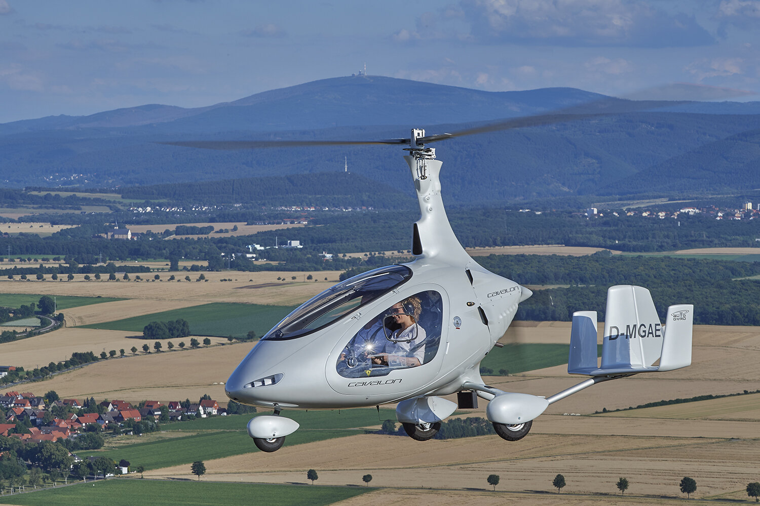
AutoGyro’s Cavalon, as shown in the photograph below, is a gyroplane currently in production that is certified under the FAA’s primary category, allowing private pilots to fly it under the Sport Pilot rule. Notice that “AutoGyro” is the name of the company. It is a two-seat, enclosed-cockpit autogyro certified under the FAA’s Primary Aircraft Category, allowing it to be flown by private pilots and those with a Sport Pilot certificate, provided it meets the Light-Sport Aircraft (LSA) criteria. Powered by a Rotax engine, the Cavalon features side-by-side seating, a pre-rotator system, and glass cockpit avionics.
Today, autogiros and gyroplanes are experiencing a slow resurgence, with modern designs offering improved safety, efficiency, and affordability. As interest in personal and light utility aviation grows, they are increasingly seen as a practical, affordable, and enjoyable alternative to helicopters and airplanes. With ongoing innovation, gyroplanes may find a niche in emerging markets, such as aerial observation and short-range urban mobility.
Autogiro, Autogyro, Gyroplane, or Gyrodyne?
Most people become confused by the names autogiro, Autogiro, autogyro, gyroplane, convertiplane, and gyrodyne. These names all relate to a specific type of rotorcraft, and while they have similarities, they also have distinct differences based on their design, function, and history. Clarification is important.
- Autogiro or autogyro: These names refer to the same type of rotorcraft. However, Juan de la Cierva trademarked the name Autogiro (with a capitalized letter A). The name autogiro (lowercase) or autogyro is now used generically for all similar aircraft. These rotorcraft use an unpowered, free-spinning rotor for lift and a conventional engine-driven propeller for forward thrust. Autogiros cannot hover.
- Gyroplane: Another generic term for an autogiro or autogyro, used interchangeably in some contexts. However, for certification and piloting purposes, the gyroplane is the name officially adopted by regulatory bodies such as the FAA and EASA. All gyroplanes operate using the same basic principles of autorotation for lift and powered propulsion for thrust. Gyroplanes cannot hover.
- Gyrodyne: A hybrid between an autogiro (or gyroplane) and a helicopter. It features a powered rotor system that enables vertical takeoff, hover, and landing, similar to a helicopter. During forward flight, the rotor may be partially powered or enter into full autorotation, with separate propulsion (usually using a propeller) providing forward thrust.
- Convertiplane: A broad classification for aircraft that can transition between vertical and horizontal flight modes, combining elements of rotorcraft and airplanes. Convertiplanes include tiltrotors, tiltwing aircraft, and even some gyrodyne-like designs. For example, the Rotordyne was often referred to as a convertiplane. These aircraft aim to combine the helicopter’s vertical takeoff and landing (VTOL) capabilities with the speed and efficiency of fixed-wing aircraft in cruise flight.
| Name | Rotor Type | Rotor Power in Flight | Main Propulsion | Can Hover? | Example Aircraft |
|---|---|---|---|---|---|
| Autogiro / Autogyro / Gyroplane | Free-spinning (autorotation) | No power applied | Engine-driven propeller | No | Cierva C.30 |
| Gyrodyne | Powered for takeoff, autorotates in cruise | No power applied or partially powered | Additional thrusting propellers | Limited hover | Fairey Rotodyne |
| Convertiplane | Varies (tiltrotors, tilt-wings, etc.) | Typically powered | Varies (tiltrotors use proprotors) | Yes | V-22 Osprey |
Scientific Research on Autogiros
Compared to most types of aircraft, autogiros have been the subject of fewer technical and scientific studies[10] with most fundamental research dating back to the 1930s. While helicopters and other rotating-wing machines[11] have undergone extensive aerodynamic analysis and technological advancements over the last century, autogiros have remained firmly in a niche category, with much fewer studies on their aerodynamics, loads, performance, as well as stability and control characteristics. Comprehensive theoretical frameworks for predictions remain largely underdeveloped compared to those for helicopters, although the underlying principles are not dissimilar, as will be further discussed.
Early Measurements
Extensive investigations into the flight performance of autogiros, primarily conducted during the 1930s and the immediate pre-WWII years by the Royal Aircraft Establishment (RAE) and the National Advisory Committee for Aeronautics (NACA), provided valuable data from flight testing and wind tunnel measurements. While the RAE had conducted experiments with autogiros and Hermann Gluert and Juan de la Cierva himself had developed a theoretical basis for their analysis as early as 1926, it was not until the early 1930s that NACA started to study rotating wings. NACA used a PCA-2 autogiro, which served as the basis for comprehensive flight and wind tunnel testing for almost eight years, until helicopters emerged.[12]
The first NACA report on the autogiro was by Wheatley,[13] who documented authoritative baseline measurements on the performance of the PCA-2 autogiro. Measurements of rates of descent and glide angles were obtained, along with estimates of the rotor lift-to-drag ratio. Separate tests of the PCA-2’s rotor were also conducted in the wind tunnel[14], allowing quantification of the rotor performance alone compared to the complete autogiro.
The figure below shows that the PCA-2’s measured aerodynamic efficiency, which was relatively poor compared to most airplanes, even in the 1930s, with a maximum lift-to-drag ( ) ratio of only about 4.5. The differences between the rotor alone and the complete aircraft reflect the relatively high parasitic drag of the airframe. However, to put the results in perspective, the performance of the rotor alone, when measured in the wind tunnel, had a maximum of approximately 7, which is comparable to that of a modern helicopter rotor. This is not surprising. The broader question is how much more efficient any rotor can be in forward flight, autorotating, or powered, which essentially behaves as a lifting wing with an aspect ratio of only
  ?
?
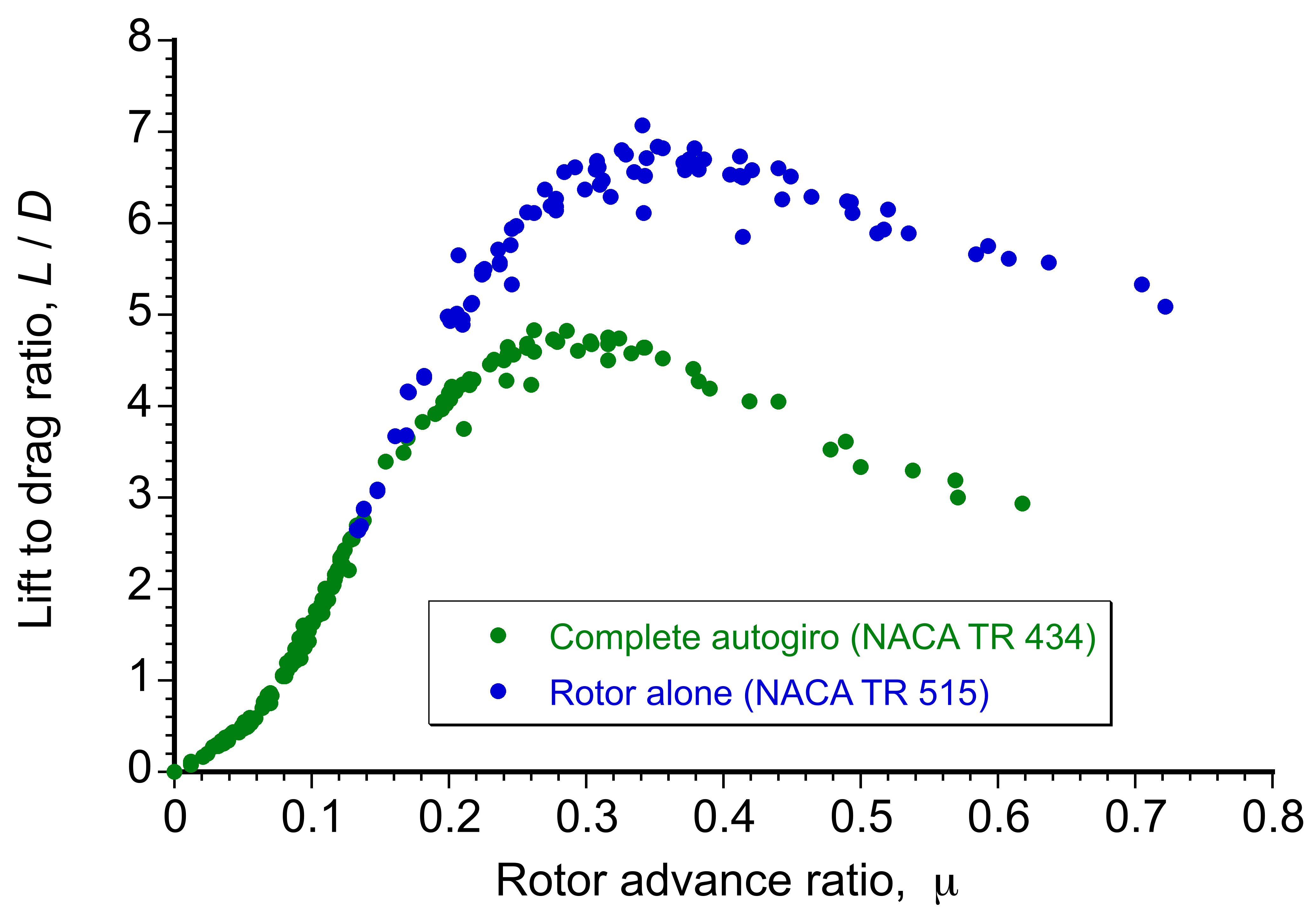
Because the autogiro rotor has a relatively low rotational speed and low disk loading compared to a helicopter, it maintains its ratio to as high as  =0.7, although not necessarily to a higher airspeed. Recall that the advance ratio is defined as the ratio of the airspeed to the rotational tip speed, i.e.,
  . A helicopter’s typical values of
  are less than 0.4. Notice from the figure above that for higher advance ratios (or tip speed ratios), the ratio drops off progressively, in part because of higher blade drag with reverse flow, retreating blade stall (which also occurs in the reverse flow region), and advancing blade compressibility effects, which are the same limiting aerodynamic issues as for a helicopter.
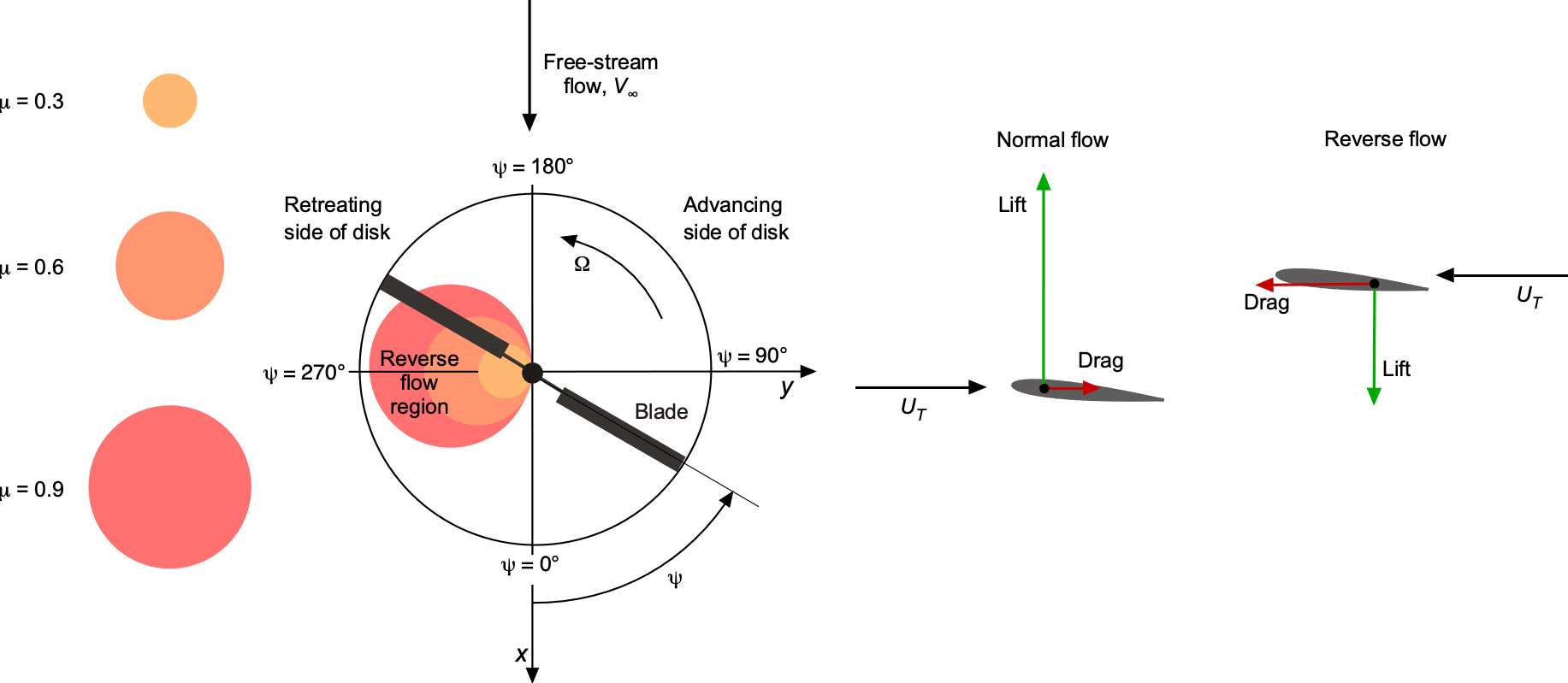
However, the autogiro has another significant problem. Due to the rotor’s lower rotational speed compared to that of a helicopter, there is a more substantial extent of reverse flow on the retreating side of the rotor disk, as illustrated in the figure below. Not only does this result in higher drag and a loss of rotor lift, but it also poses a potential aeroelastic issue (i.e., blade twisting) due to the movement of the center of lift from near the 1/4-chord back to the 3/4-chord. Notice that the reverse flow region encompasses a circle of diameter on the retreating side of the rotor disk.
Defining the Reverse Flow Boundary on the Rotor Disk
The reverse flow region on a rotor disk is defined by the condition where the in-plane component of the relative velocity, i.e.,  , becomes zero or negative. This condition occurs when the sum of the rotational and translational velocity components vanishes, i.e.,
![\[ U_T = \Omega y + V_{\infty} \sin\psi = 0 \]](https://eaglepubs.erau.edu/app/uploads/quicklatex/quicklatex.com-59743e4fc33f591cf79e434d5dacd7f3_l3.svg "Rendered by QuickLaTeX.com")
Solving for the spanwise coordinate  , the boundary of the reverse flow region becomes
![\[ y = -\frac{V_{\infty}}{\Omega} \sin\psi = -R\mu \sin\psi \]](https://eaglepubs.erau.edu/app/uploads/quicklatex/quicklatex.com-4de63770a72716b3bb73d91aab9a0122_l3.svg "Rendered by QuickLaTeX.com")
Here,  is the rotor radius,
  is the rotor’s rotational angular velocity,
  is the forward flight speed (airspeed),
  is the blade azimuth angle, and
  is the advance ratio. Normalizing the radial position using
  , the reverse flow boundary becomes
![\[ r = -\mu \sin\psi \]](https://eaglepubs.erau.edu/app/uploads/quicklatex/quicklatex.com-17ad373aa396b2f39caf0bc3d2602926_l3.svg "Rendered by QuickLaTeX.com")
which is the equation of a circle in polar coordinates. The coordinates can be expressed in Cartesian form to visualize this boundary in the rotor disk plane. Letting  and
and  , then normalizing by radius , gives
![\begin{eqnarray*} x' & = & \cos\psi \\[4pt] y' & = & -\mu \sin\psi \end{eqnarray*}](https://eaglepubs.erau.edu/app/uploads/quicklatex/quicklatex.com-5ea24cdd2c9dafefd31f7987cfcfdc3e_l3.svg "Rendered by QuickLaTeX.com")
These parametric equations trace a circle of radius  , centered at
  in the normalized
  plane. Completing the square confirms this result, i.e.,
![\[ { x'^2 + \left(y' + \frac{\mu}{2}\right)^2 = \left(\frac{\mu}{2}\right)^2 } \]](https://eaglepubs.erau.edu/app/uploads/quicklatex/quicklatex.com-45c2214f884480e0514b72c5c51f62ac_l3.svg "Rendered by QuickLaTeX.com")
This equation then defines the rotor disk’s reverse flow boundary, which increases with the advance ratio on the retreating side, where  .
.
Theoretical Studies
Theoretical studies of the autogiro led to one of the first comprehensive aerodynamic analyses of the rotor system.[15] Later, a now classic study by Bailey[16] extended the earlier work of Glauert[17] and included the treatment of blade twist, reverse flow, nonuniform inflow, and tip-loss effects on the aerodynamics of the rotor. The predictions were shown to agree with both flight and wind tunnel measurements. The NACA worked extensively on several other technical problems, both from an experimental and a theoretical perspective, that were to occur during the maturation process of the autogiro. This work included studies of rotor dynamics, vibration, airfoil sections, jump takeoffs, and ground resonance.[18]
From the 1940s until the 1980s, there were very few technical publications on autogiros or gyroplanes. During this time, there was little interest in commercial or military applications for autogiros or gyroplanes, resulting in a lack of funding sources. Any further developments of the machine were driven by amateur homebuilders and small-scale manufacturers, primarily for recreational use. Unfortunately, this period has also been accompanied by a disproportionately high number of accidents involving gyroplanes, which reflects a lack of understanding of the machine’s underlying nature, including its autorotational characteristics and operational limits. While some incidents may be attributed to pilot error or mechanical failure, others likely stem from fundamental design flaws or unapproved modifications. In the United Kingdom, the Civil Aviation Authority (CAA) grounded all gyroplanes in 1991 following a series of fatal accidents. Fortunately, this decision also rekindled research efforts from the scientific community to improve the understanding of the autogiro’s aerodynamics, stability, control, and safety.
Recent Theoretical Studies
Since the 1990s, Stuart Houston and Gareth Padfield have made several advances in the scientific understanding of gyroplane flight dynamics. Their research focused on developing high-fidelity, nonlinear flight dynamics models explicitly tailored to autogiros and gyroplanes, which had previously lacked rigorous academic attention. This work involved building simulation environments to analyze their behavior under various flight conditions, including maneuvers associated with accidents, such as power push-overs (PPOs). PPO is a condition where, in powered autorotative flight, the rotor’s angle of attack becomes too low to maintain autorotation, so rotor speed can quickly decay, causing a sudden loss of lift and a departure from controlled flight. It is a form of precessional blade stall, which almost immediately reduces rotor speed.
By simulating both the static and dynamic stability characteristics and validating results against flight test data, this research helped reveal fundamental control and design issues with gyroplanes. Therefore, it provided valuable insights for improving safety, guiding regulatory discussions, and informing the design of safer and more stable gyroplane configurations.[19] Houston and Thomson give a recent summary.[20] They conclude with an encouraging statement that “the mathematical modeling of gyroplanes for the simulation and analysis of trim, stability, and control presents no special difficulty and the conventional techniques, methods, and formulations familiar to the rotary-wing community are directly applicable.”
Autorotation as an Energy Balance
Autorotation is an established rotor energy balance where a rotor has self-sustained rotation without any applied shaft torque, meaning that the net torque is zero, or  = 0. Unlike helicopters, where the rotor shaft is powered, an autogiro’s rotor must always be in autorotation. The energy needed to sustain rotor motion is derived from the kinetic energy in the relative airflow directed upward through the rotor disk. This means the rotor disk must operate at a slight angle of attack with a backward tilt. Because of the relatively lower disk loading,
  , of an autogiro’s rotor compared to a helicopter, only a minimal upward airflow is required to maintain an autorotational condition, so it requires only a small forward airspeed to sustain flight.
While this phenomenon of autorotation is fundamental to the flight of autogiros, it is also essential for helicopters because it allows for a controlled autorotational descent and landing in the event of engine failure. Engine failure rarely poses a critical safety issue in an autogiro because the rotor remains in autorotation at all times, allowing the aircraft to descend safely to the ground. However, improper piloting techniques, such as a PPO, can still cause the rotor to exit the autorotative state, potentially compromising flight safety, a concern previously noted.
Quantifying Autorotation
To understand autorotation, it is helpful to first analyze the problem using the principles surrounding the essential energy balance in flight, in conjunction with the principles that underlie the momentum and blade element theories of the shaft-driven rotor. Historically, these methods are derived from the analyses and models developed by Hermann Glauert (RAE), Christopher Lock (RAE), Arthur Bennett (Cierva Autogiro Company), and John Wheatley (NACA).
The autorotational equilibrium equation for a torque balance on the rotor can be written as
(1) 
where  is the rotor’s thrust, is its rotational frequency,
  is the average induced velocity through the rotor disk (positive downward),
  is the rate of descent, is the airspeed, and
  is the rotor disk angle of attack, which is considered as negative[21] when tilted back, i.e., the value of
  is negative.
The solution for = 0 depends on adequately evaluating the induced velocity, . To this end, can be determined using momentum theory, the solution to the standard inflow equation derived for helicopters in the previous chapter, or an empirical approximation to in regions of its invalidity. Non-ideal induced losses, which in aggregate represent several physical phenomena, including tip loss, can be accounted for by an increase in relative to the ideal value obtained using momentum theory by using the induced power factor,  , where
  1, and typically between 1.15 and 1.25.
The  term in Eq. 1 represents the effect of profile drag on the rotor, which depends on the rotor’s solidity and the average drag coefficients of the airfoil sections that comprise it. Consequently, a rotor with larger solidity or more significant airfoil drag coefficients will require a steeper descent rate and/or a higher airspeed to maintain itself in autorotation.
It will also be apparent from Eq. 1 that the autorotational condition where  can occur over many ranges of conditions, i.e., for different combinations of , , and . When reflecting on his experiments with autogiros in the wind tunnel, Juan de la Cierva wrote about his results, “…among them the determination of the fact that the rotor would continue to turn at every possible angle of flight, a point that was somewhat disputed by critics of my earlier experiments.” In this regard, Eq. 1 states that for autorotation to occur and = 0, there must be a negative climb velocity, i.e., a descent or, in general, an upward component of flow through the rotor disk, which then provides the kinetic energy source to drive the rotor and balance the sum of the induced and profile losses.
In practice, this means that the autogiro must descend to sustain the rotor in autorotation or have its rotor disk plane tilted back so that a component of the airspeed acts upward through the rotor disk. Therefore, in terms of an energy balance, the potential energy (altitude) and/or kinetic energy (airspeed) can be used to balance the sum of the rotor’s induced and profile losses, thereby maintaining its spin.
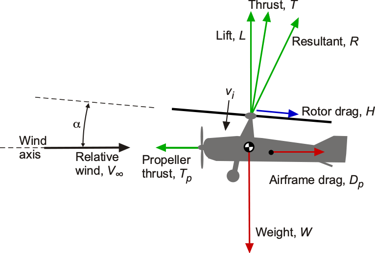
Resultant Force on the Autorotating Rotor
The aerodynamic analysis of autorotation can proceed from an examination of the resultant force, , on the autorotating rotor, as shown in the figure below, which can be expressed in terms of the lift and drag forces, i.e.,
(2) 
where  is lift on the rotor and
  is its drag. In coefficient form, this equation is written as
(3) 
where the rotor coefficients are defined as
(4) 
The resultant velocity, , can be written as  , where
  is the forward velocity and is the descent velocity, i.e., the rate of descent, so that
(5) 
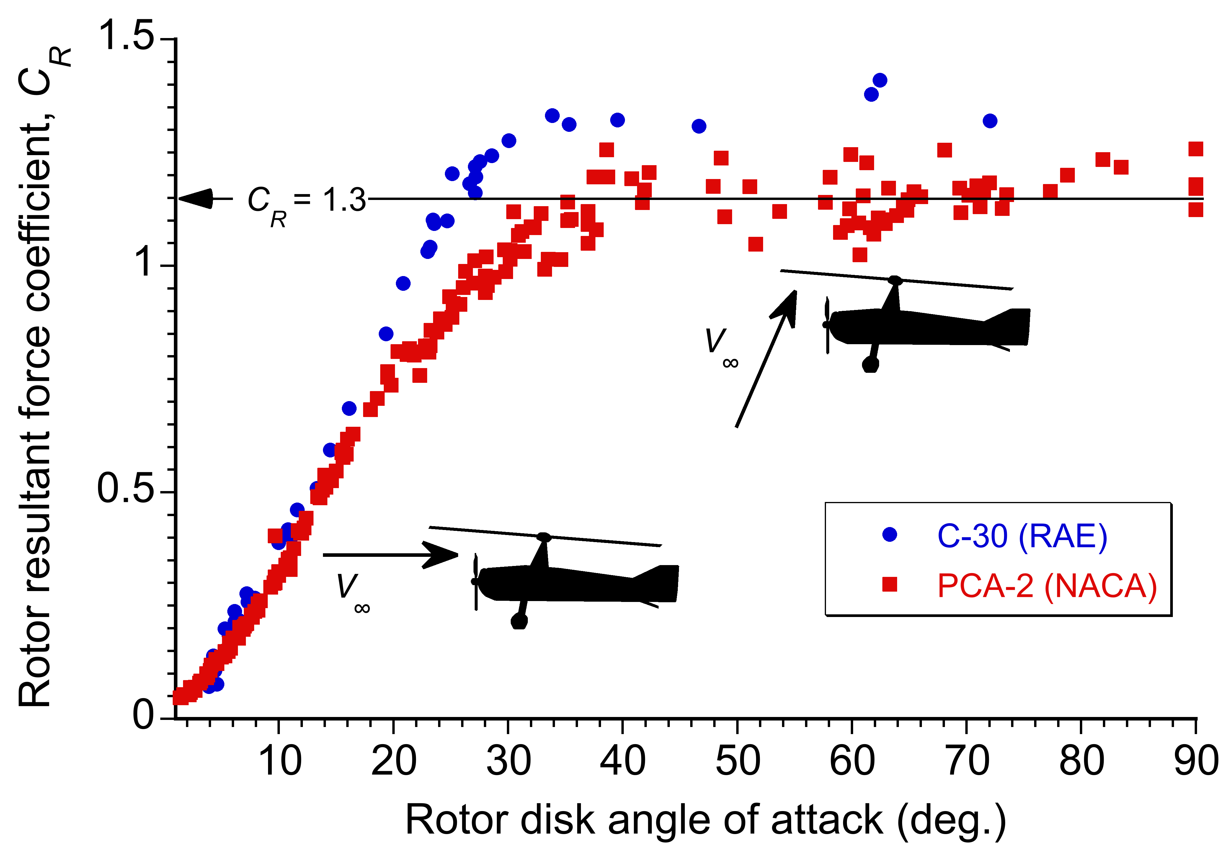
Measurements documenting the performance of autogiros are scarce, as previously mentioned, and date back to the 1930s. Some of the most detailed in-flight measurements were conducted by the Royal Aircraft Establishment (RAE) using a Cierva C.30 and by the NACA using a Pitcairn PCA-2. A combined set of measurements for two autogiros derived from flight test data[22] are shown in the figure below. Notably, at high angles of attack (above  ), the values of
  firmly plateau at approximately 1.3, nearly matching the drag coefficient
  of a parachute in normal flow. Indeed, measurements for bluff bodies show that
  1.3 for an open hemisphere, reinforcing this analogy. Therefore, in vertical (or near vertical) autorotation, the rotor behaves aerodynamically somewhat like a parachute.
Vertical Autorotation
In vertical autorotation or flight at low airspeeds with the rotor disk at a high angle of attack with respect to the oncoming flow, i.e., the airspeed vector, , the rotor operates in a turbulent wake state for which the momentum theory and the solution to the inflow equation afford no valid solution. Nevertheless, semi-empirical approximations to the inflow are possible. At higher forward speeds, however, the autorotative flow state becomes significantly smoother with a well-defined control volume, and the assumptions of momentum theory are broadly applicable.
For almost vertical descents and at larger disk angles of attack, it is possible to equate the resultant force on the rotor to the weight of the autogiro (i.e.,  ). For a series of horizontal velocities, , at the steeper angles of attack where = =1.3, the rate of descent in autorotation, , can be solved using
(6) 
or in nondimensional terms
(7) 
Notice that for a pure vertical rate of descent ( ), this equation predicts
  /
/ = 1.8. Therefore,
(8) 
or in SI units, then
(9) 
These latter equations show that the autorotational descent rate is proportional to the square root of the rotor disk loading, , which is equivalent to  , the aircraft’s weight per unit disk area. Cierva’s early autogiros had disk loadings of approximately 2 lb/ft
 (96 N/m), representing modern autogiro designs. The descent rate in autorotation also depends on rotor blade efficiency (low-drag airfoils and optimized solidity reduce the required descent rate. At sea level, this results in a vertical autorotational descent rate of approximately 39 ft/s (12 m/s) or 2,340 ft/min (713 m/min). While the rate of descent is too high to sustain to the ground, adding some forward speed will allow the pilot to flare the machine to a soft landing.
Autorotation in Forward Flight
The performance of the autogiro in forward flight can be approached using the same basic principles of analysis (momentum and blade element theories) applied to the helicopter rotor. Consider the autogiro in forward flight, as shown in the figure below. Vertical force equilibrium gives
(10) 
and horizontal equilibrium gives
(11) 
Using energy principles, the power required for flight,  , is
, is
(12) 
so the net drag force on the autogiro can be written as
(13) 
The power for flight can be written as the sum of the induced power,  , profile power,
  , and parasitic power needed to overcome airframe drag,
  , i.e.,
(14) 
While the rotor of an autogiro is unpowered at the shaft, power is still required to turn the rotor and overcome all sources of aerodynamic losses, as previously discussed for the vertical descent case. This energy source in forward flight is the kinetic energy of the relative flow upward through the rotor, which is produced by setting the rotor disk at an angle of attack and propelling the aircraft forward with the engine and its attached propeller.
These power components are conveniently written in their nondimensional form as
(15) 
where each component can be estimated, similar to what is done for the helicopter, using
(16) ![\begin{eqnarray*} C_{P_{0}} & = & \frac{\sigma C_{d_{0}}}{8} \left( 1 + 3\mu^2 + \frac{3}{8} \mu^4 \right) \mbox{~~including reverse flow} \\[6pt] C_{P_{i}} & = & \frac{ \kappa \, C_T^2}{2 \sqrt{\mu^2 + \lambda_i^2}} \approx \frac{\kappa \, C_T^2}{2 \mu} \mbox{~~in high-speed flight} \\[6pt] C_{P_{p}} & = & \frac{1}{2} \left( \frac{f}{A} \right) \mu^3 \end{eqnarray*}](https://eaglepubs.erau.edu/app/uploads/quicklatex/quicklatex.com-cb2674f7daa0229d055a3c0a4e9e6766_l3.svg "Rendered by QuickLaTeX.com")
The effects of reverse flow in Eq. 16 assume that the value of  in both regular (nose-to-tail) flow and reverse (tail-to-nose) flow is the same, but this is unlikely to occur in practice. To account for that, the
  term is added based on empirical data from flight tests and wind tunnel measurements. This term accounts for the fact that the blades will inevitably stall in the reverse flow region as the relative flow vector changes from being directed from the leading edge toward the trailing edge.
The induced inflow through the rotor is given by numerically solving the inflow equation (as is used for the helicopter), i.e.,
(17) 
with the usual limits of its validity being applied, as described in the previous chapter.
Other methods based on blade element theory indicate that the induced power factor for an autorotating rotor is typically slightly larger than that of the powered rotor in the normal working state. Therefore, it is sufficient to assume, on average, that = 1.2 for autogiro performance calculations. Notice that the profile contribution to the power (or drag) must model the performance of the rotor at higher values of because of the typically lower values of of the autorotating rotor at similar airspeeds to that of a helicopter.
Finally, the propulsive force on the autogiro,  , must be produced by a propeller with an assumed aerodynamic efficiency
  . Therefore, the net power required for the autogiro,
  is
is
(18) 
Several provisions exist for using the result in Eq. 18. First, it will not be applicable at very low airspeeds because it is apparent that  (or
(or  ) will become singular. However, the autogiro cannot sustain level flight here anyway because of the maximum resultant force coefficient that can be sustained on an autorotating rotor, i.e.,
  . Under conditions where level flight cannot be sustained, the autogiro will begin to descend, and potential energy (altitude) must be given up to maintain the rotor in autorotation. Second, as previously discussed, because of its lower tip speed compared to a helicopter, an autogiro’s rotor operates at higher values of , so the applicability of the approximation used for the rotor drag with the reverse flow (given by Eq. 16) must be further examined. Third, the theory cannot be applied when the disk angle of attack is large, although this condition typically occurs at lower airspeeds and steeper descent angles.
Therefore, it can be concluded that Eq. 18 will apply over most practical level-flight conditions and airspeeds. However, it will now be apparent that this energy analysis gives no information about the rotor disk angle of attack required to produce autorotation, a parameter essential to its analysis.
Rotor Disk Angle of Attack
A further analysis based on a force balance must consider the flow conditions required to produce autorotation, i.e., the rotor’s angle of attack to produce autorotation at a given airspeed must now be determined. Glauert used the following principles to solve his “lifting windmill” problem. To produce autorotation, there must be a component of flow upward through the disk, i.e., a component  . Because the rotor produces thrust and lift, it also creates a self-induced velocity, . Therefore, the net upward flow through the rotor will be
  , where is not known a priori.
Autorotational conditions will be obtained when the angle of attack and upward flow are sufficient to create a net torque to overcome both the rotor’s induced and rotational losses, so that the net shaft torque will be zero. These losses can be written as
(19) 
where  is the rotational component of profile torque on the rotor, which can be approximated using
(20) 
when accounting for reverse flow, where the inflow ratio is given by
(21) 
Notice that a negative sign preceding the must be used here because the disk is tilted back compared to the helicopter case (sign convention). Therefore,
(22) 
which can be solved numerically for the value of required to produce autorotation; that is, the value of required at any to produce zero net torque at the rotor shaft. Because vertical force equilibrium must be simultaneously satisfied using Eq. 10, the rotor thrust must also increase as increases because the airspeed decreases, i.e., because  . This flight condition will apply to the lower limit of .
Having solved for to produce autorotation, the drag on the autogiro will be
(23) 
where the rotor drag force coefficient is
(24) 
when including the effects of reverse flow. The shaft power required for flight is then found using
(25) 
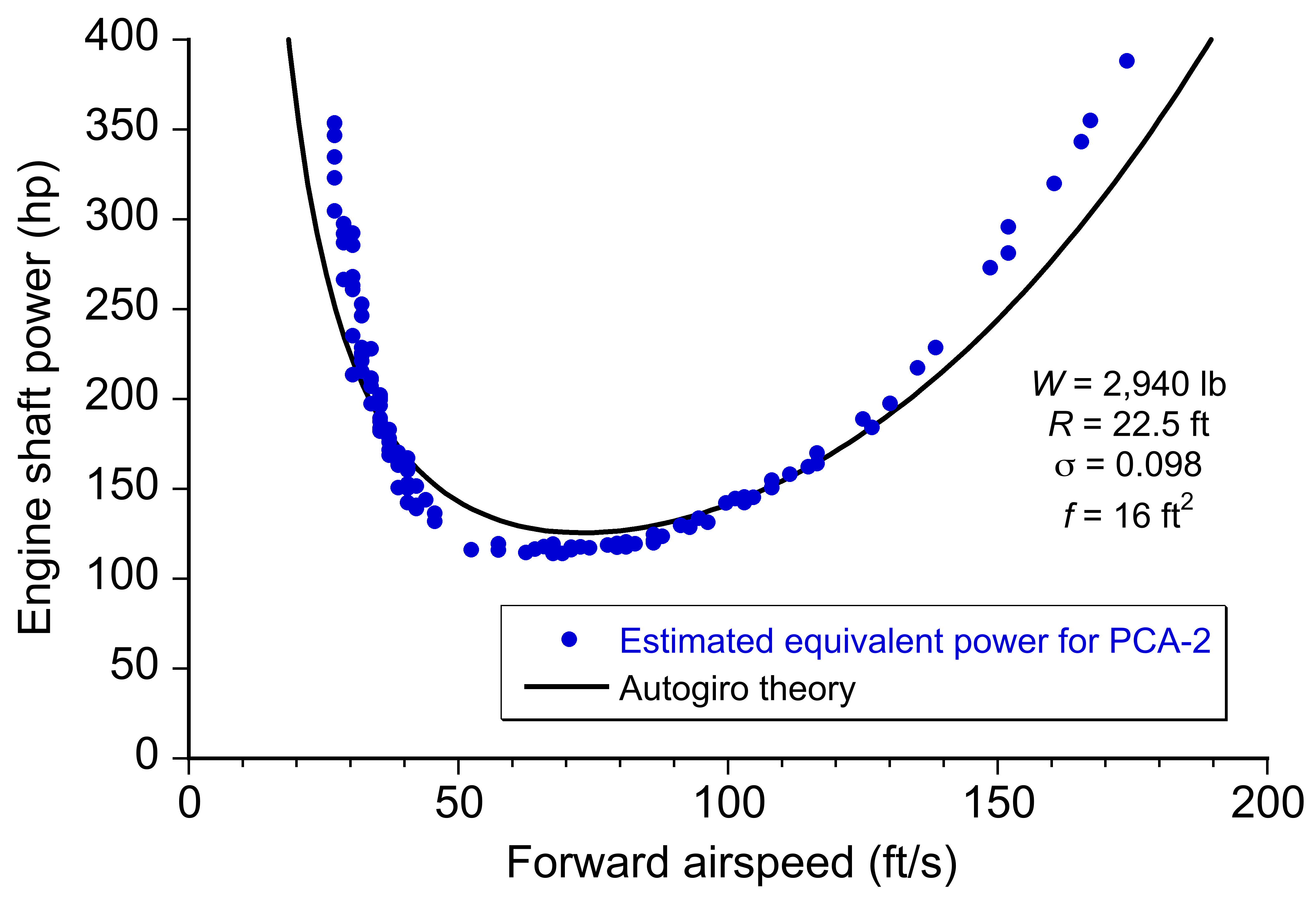
The figure below shows a representative curve of power required versus airspeed for the PCA-2 autogiro, for which measurements are available. While direct engine power measurements were unavailable, the propulsive thrust can be derived from the aircraft’s weight,  , and the measured values of , i.e.,
(26) 
This type of performance analysis gives predictions that agree quite well with measurements. Notice, however, that compared to a typical helicopter curve, the power requirements for an autogiro increase rapidly as airspeed decreases. The autogiro’s performance under these conditions is limited by either the power available or the maximum attainable rotor lift coefficient. Furthermore, the power requirements increase rapidly at higher airspeeds, resulting from the relatively high parasitic airframe drag of the early autogiros.
Gliding Performance
The foregoing theory can also predict the autogiro’s gliding (power-off) rate of descent, which is essential for assessing landing characteristics. Based on an energy balance and solving for the rate of descent, it is apparent from the figure below that the theory agrees well with the measured flight performance of both the PCA-2 and C.30 Autogiros, but only at higher forward flight speeds. This is because of the failure of the momentum theory to predict the induced velocity through the rotor at high disk angles of attack, i.e., low airspeeds and higher rates of descent, which is because the rotor operates in the turbulent wake state, and no unique control volume can be applied to solve the conservation equations. The autorotational rate of descent, , for both machines is plotted below as a function of forward speed, , with both parameters nondimensionalized by  . This nondimensionalization removes the effects of airplane weight and disk loading from the results, allowing for a more generalized type of comparison.
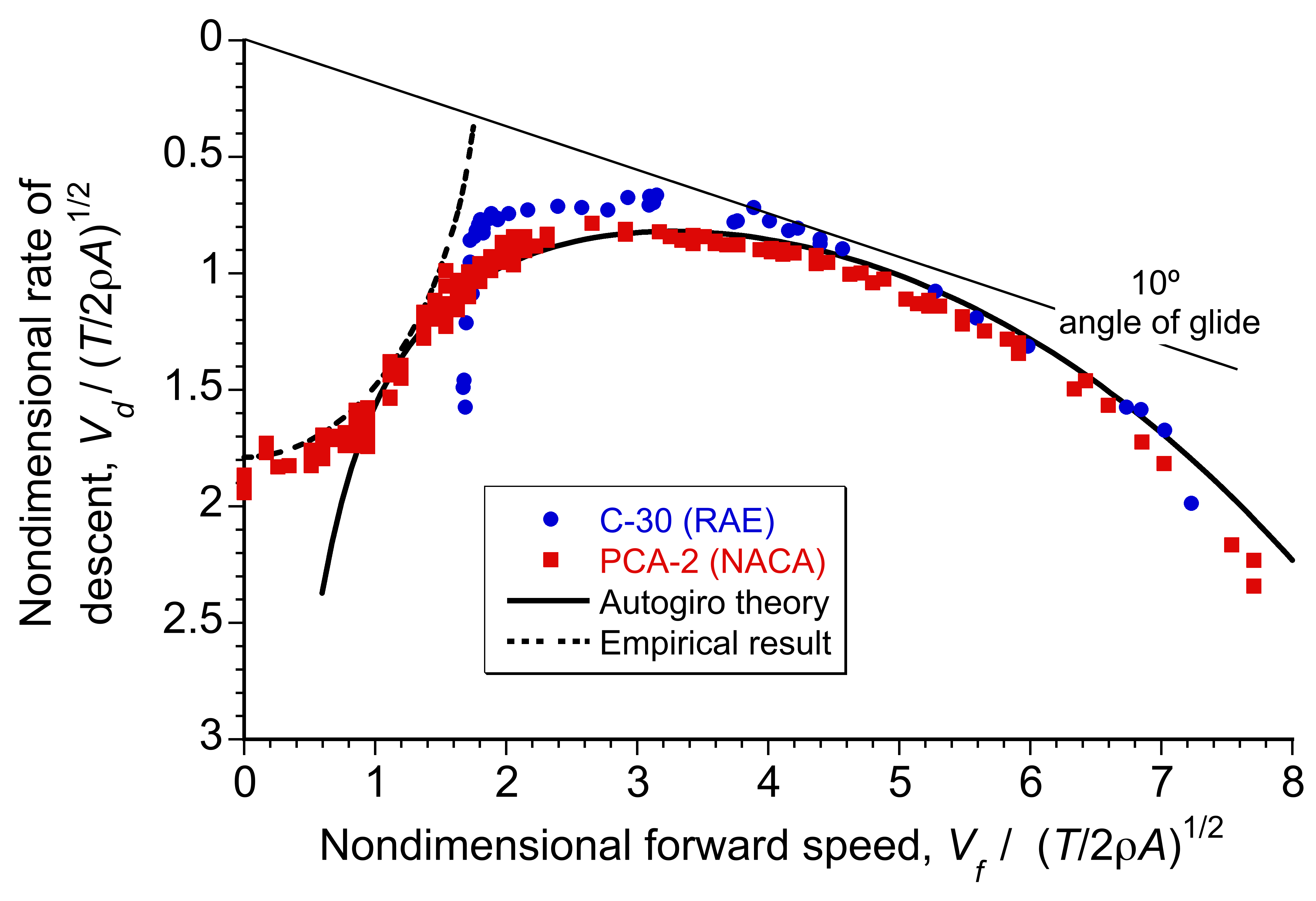
Notice that the autorotative rate of descent decreases quickly with increasing forward speed, but only to a point. The measurements illustrate a sharp reduction in the autorotational rate of descent as forward speed increases. A minimum rate of descent is reached at approximately  , which in practical terms corresponds to an airspeed of approximately 35–40 knots (65–74 km/h). At this point, aerodynamic losses at the rotor are minimized, resulting in the most efficient descent or gliding profile. Beyond this forward speed, the rate of descent gradually increases again as additional aerodynamic losses from parasitic drag at higher angles of attack become significant.
The foregoing measurements indicate that the vertical rate of descent occurs at approximately  = 1.8 to 1.9, which aligns well with the theoretical prediction given previously in Eq. 8. As noted, there is no exact theoretical framework for describing rotor aerodynamics in autorotation when the rotor has no forward (translational) motion. However, as airspeed increases, the standard rotor momentum theory provides an increasingly accurate aerodynamic approximation of autorotational flight conditions and the rate of descent.
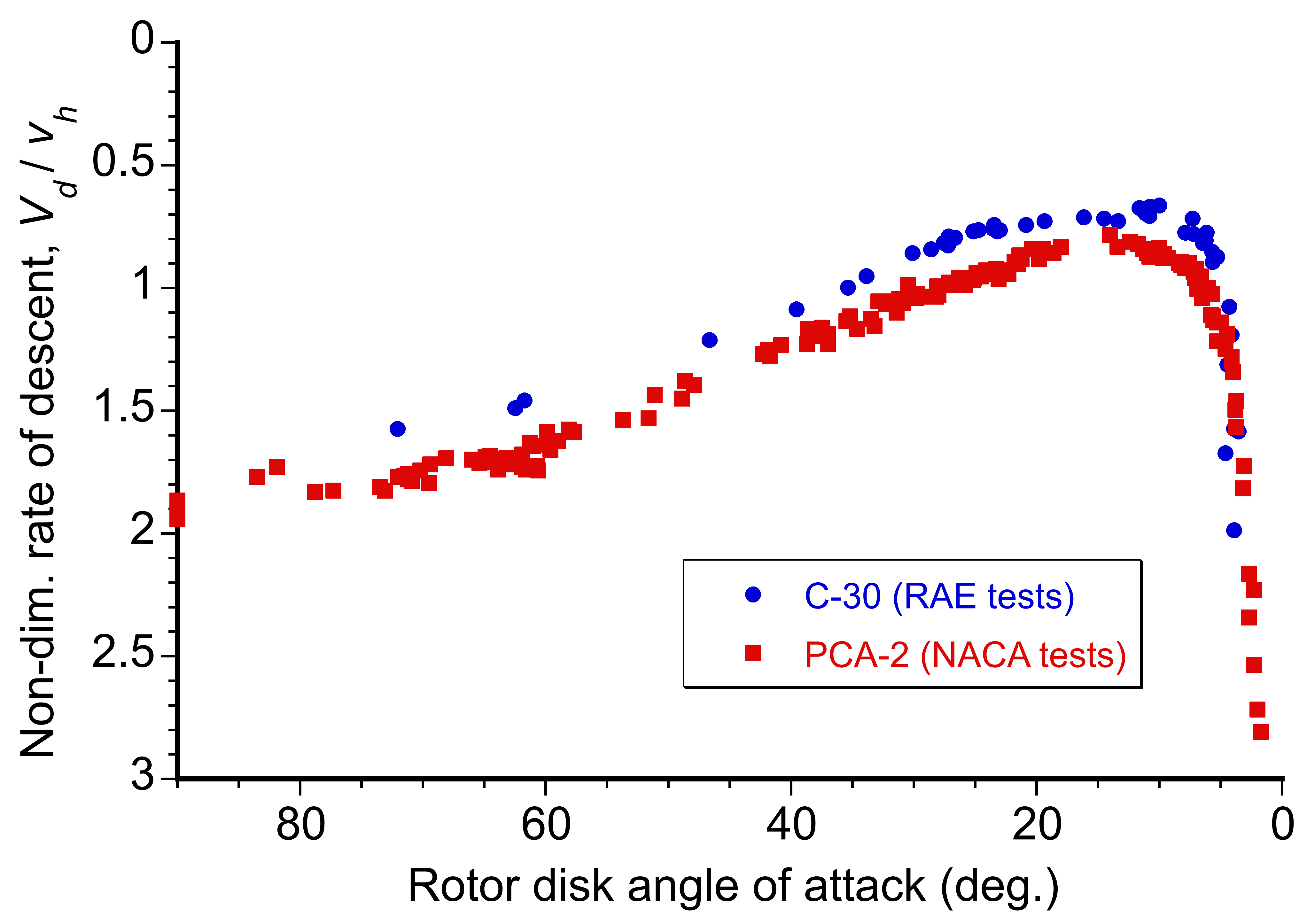
Also of interest is the rotor disk angle of attack needed for an equilibrium autorotational rate of descent. While the foregoing measurements were performed in descending “gliding” flight, autorotation is also possible in level flight, driven forward by a propeller to propel the autogiro. All that is required is that the rotor disk be held at a sufficient angle such that the component of the relative airspeed vector upwards through the disk causes the rotor to autorotate. Indeed, in Cierva’s words, “It makes no difference at what angle the Autogiro is climbing or flying. The blades are always gliding toward a point a little below the focus of forward flight. Therefore, autorotation can’t stop while the machine goes anywhere.” This bold statement, however, overlooks the possibility of poor piloting technique, a concern previously mentioned.
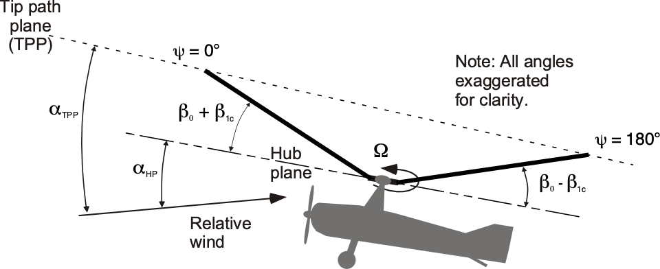
The results in the figure below show the measured “hub plane” angle of attack as a function of the resultant nondimensional velocity of the aircraft. In a pure vertical descent, it is apparent that the tip-path-plane (TPP) and hub-plane (HP) angles of attack are both essentially 90 , i.e., the resultant wind, in this case, is perpendicular to the rotor disk. As forward speed increases, the hub plane must make a progressively smaller angle to the relative wind to enable autorotation. At higher speeds, the rotor must be held at only a shallow angle to produce sufficient lift in the autorotational state.
The rotor TPP angle is also inclined backward, but it is not equal to the HP angle of attack due to blade flapping. The natural tendency to produce longitudinal flapping (i.e., a  component) with forward speed increases the component of velocity upward through the disk, which means the hub plane angle is always relatively small in forward flight. The TPP has a positive angle of attack to the HP and the relative wind, much like a wing under these conditions.
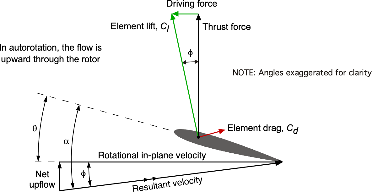
Autorotation at the Blade Element Level
As previously noted, Juan de la Cierva concluded that there could be numerous combinations of rotor operating conditions where the net torque on the rotor shaft is zero. Consider the flow environment encountered at a representative blade element on the rotor during autorotation, as shown in the figure below, where the relative velocity is directed upward toward the rotor. For exact autorotational equilibrium at that section, the inflow angle,  , must be such that there is no net in-plane sectional force and, therefore, no contribution to rotor torque, i.e., for force equilibrium at that section
(27) 
or in coefficient form, then
(28) 
Notice that the local section angle of attack in autorotational equilibrium, , is given by
(29) 
where  is the blade pitch angle.
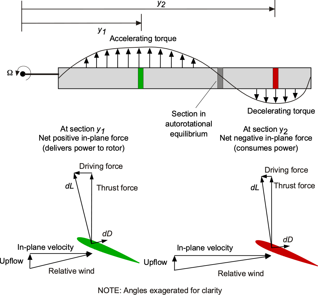
However, this is an equilibrium condition that cannot exist throughout the entire blade. Only one radial station on the blade can be in proper autorotational equilibrium. In general, some portions of the rotor will absorb power from the relative airstream and drive the rotor, and some portions will consume power such that the net torque at the rotor shaft is zero, i.e.,
(30) 
Indeed, it is found that when in autorotational equilibrium, the induced angles of attack over the inboard stations of the blade are relatively high. Near the tip, the values of are relatively low, as shown in the figure below. Therefore, at the inboard part of the blade, the net angle of attack results in a forward inclination of the sectional lift vector, providing a propulsive component larger than the profile drag and creating an accelerating torque. This blade element can be said to absorb energy from the relative airstream and so drive the rotor. Toward the tip of the blade where is lower, these sections of the blade absorb energy because the propulsive component, as a result of the forward inclination of the lift vector, is insufficient to overcome the profile drag there, i.e., a net decelerating torque is produced on the rotor.
Therefore, it will be apparent that in the fully established autorotational state at a given blade collective pitch angle, the rotor speed will automatically adjust its condition until a zero torque equilibrium is obtained. Assuming unstalled blades, this is a stable equilibrium because if increases, will decrease, and the region of accelerating torque will decrease inboard, which tends to reduce rotor speed. Conversely, if the rotor speed decreases, then will increase, and the region of accelerating torque will grow outward. Therefore, when fully established in the autorotative state, the rotor naturally seeks to find its equilibrium rotational speed in response to changing flight conditions. This inherent characteristic of the rotor gives the autogiro very safe and forgiving flight characteristics, provided it is flown within its established flight envelope.
Notice that in the autorotational state, the blade pitch must always be low, and the angles of attack must be low enough to ensure that the inboard blade sections never reach high enough angles of attack to stall. Stall may occur if the rotor speed decays below an acceptable threshold, such as when the disk angle of attack becomes nose-down or a reduced or negative load factor is applied to the machine. These are flight conditions to be avoided. If blade stall does inadvertently occur, the outward propagation of stall from the blade root region will likely result in a reduction in rotor speed.
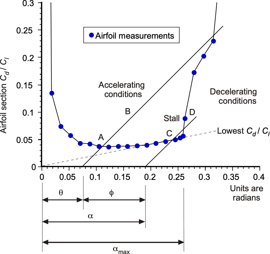
In this regard, consider the autorotation diagram shown below, where the blade section  is plotted versus the angle of attack. For a single section in equilibrium, then
(31) 
where is the blade pitch angle. This equation represents a series of points that form a straight line for a given value of and inflow angle . The intersection of this line with the measured data at point A corresponds to the equilibrium condition where  . Above this point, say at point B,
  , so this condition represents an accelerating torque. Point C is where
  , and this represents a decelerating torque condition. Notice that above a certain blade pitch angle, the aerodynamic angles of attack will become too high, and stall will occur. For operation at point D, then autorotational equilibrium is impossible. The onset of stall on an autorotating rotor will rapidly cause the rotor speed to decay, which can be catastrophic and irrecoverable.
Pre-Rotating the Rotor
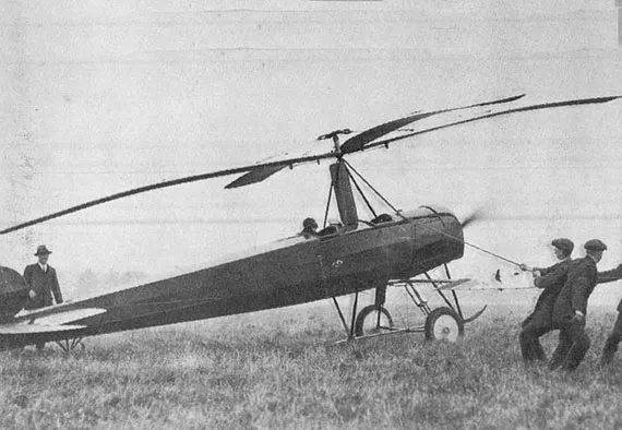
An autogiro’s rotor is unpowered in flight, and to function, it must be spun up to a sufficient speed before takeoff to generate lift. Initially, Juan de la Cierva relied on a time-consuming but straightforward method to have the pilot taxi around, allowing the rotor to accelerate passively to an initial rotational speed. Another prerotation technique, the “spinning top” method, was introduced to pre-rotate the rotor. In this technique, a rope was wound around pegs on the rotor shaft and either pulled manually, as shown in the photograph below, or unwound by taxiing the machine away from an anchor point.
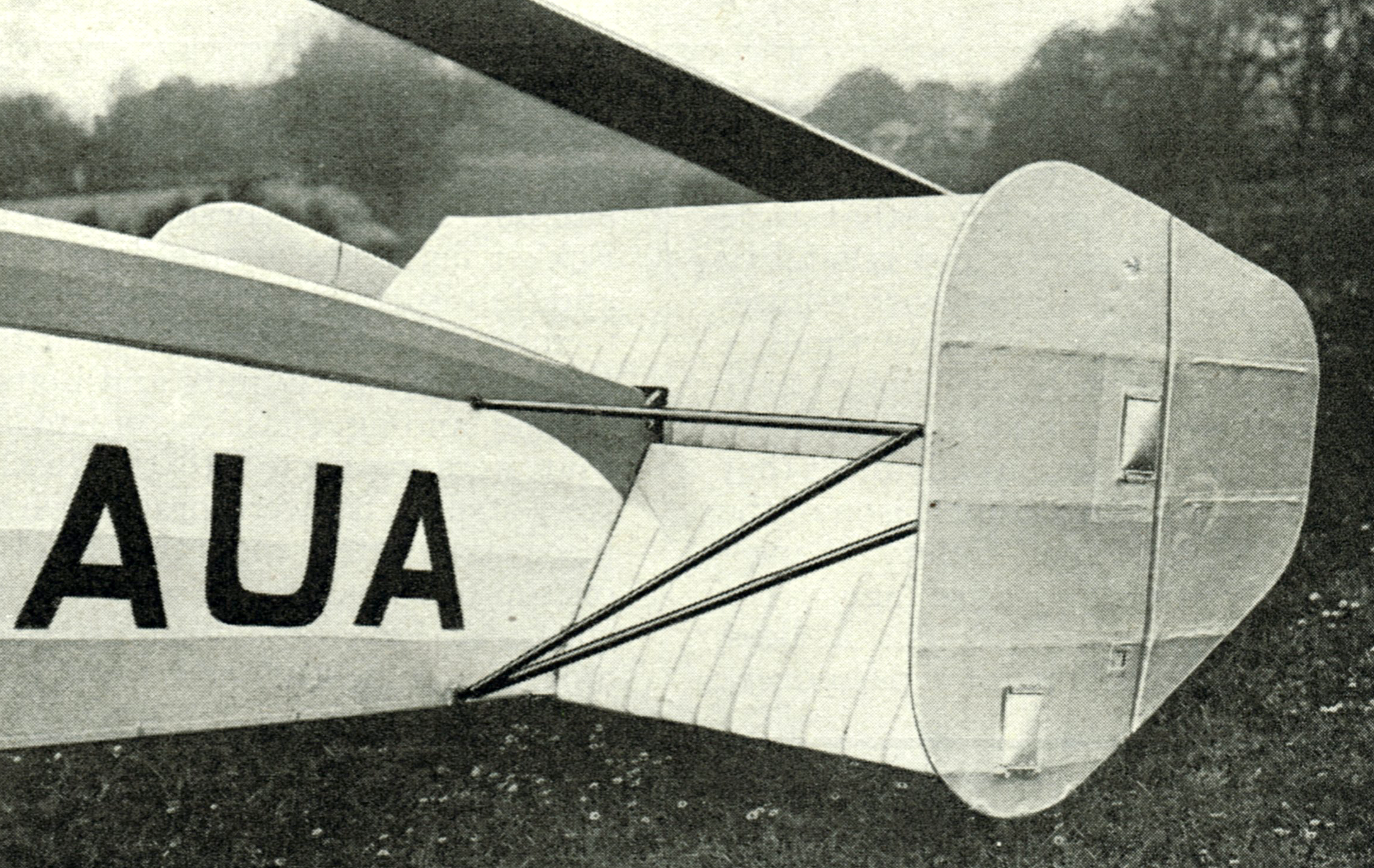
Another alternative method was devised in 1929 with the Cierva C.12, which introduced an aerodynamic prerotation system known as the “Scorpion” biplane tail, as shown in the photograph below. This tail design deflected the propeller slipstream upward into the rotor while the aircraft was stationary with the brakes engaged and the throttle wide open. Once the rotor speed accelerated to an acceptable value, the tail incidence was reset for takeoff. Although this method successfully accelerated the rotor without external assistance, it significantly increased structural weight, added drag, and gave directional (yaw) control issues at low airspeeds.
Despite these limitations, the scorpion tail remained a viable interim solution as a pre-rotator and was implemented in several autogiro models. By 1930, Cierva engineers had developed a far more practical and lightweight mechanical prerotator, which allowed pilots to quickly and efficiently spin up the rotor without relying on airflow or external mechanisms. This innovation, still in use today, significantly improved the operational practicality of autogiros, making them more accessible for routine use and paving the way for their broader adoption in the aviation industry.
Autogiros vs. Helicopters
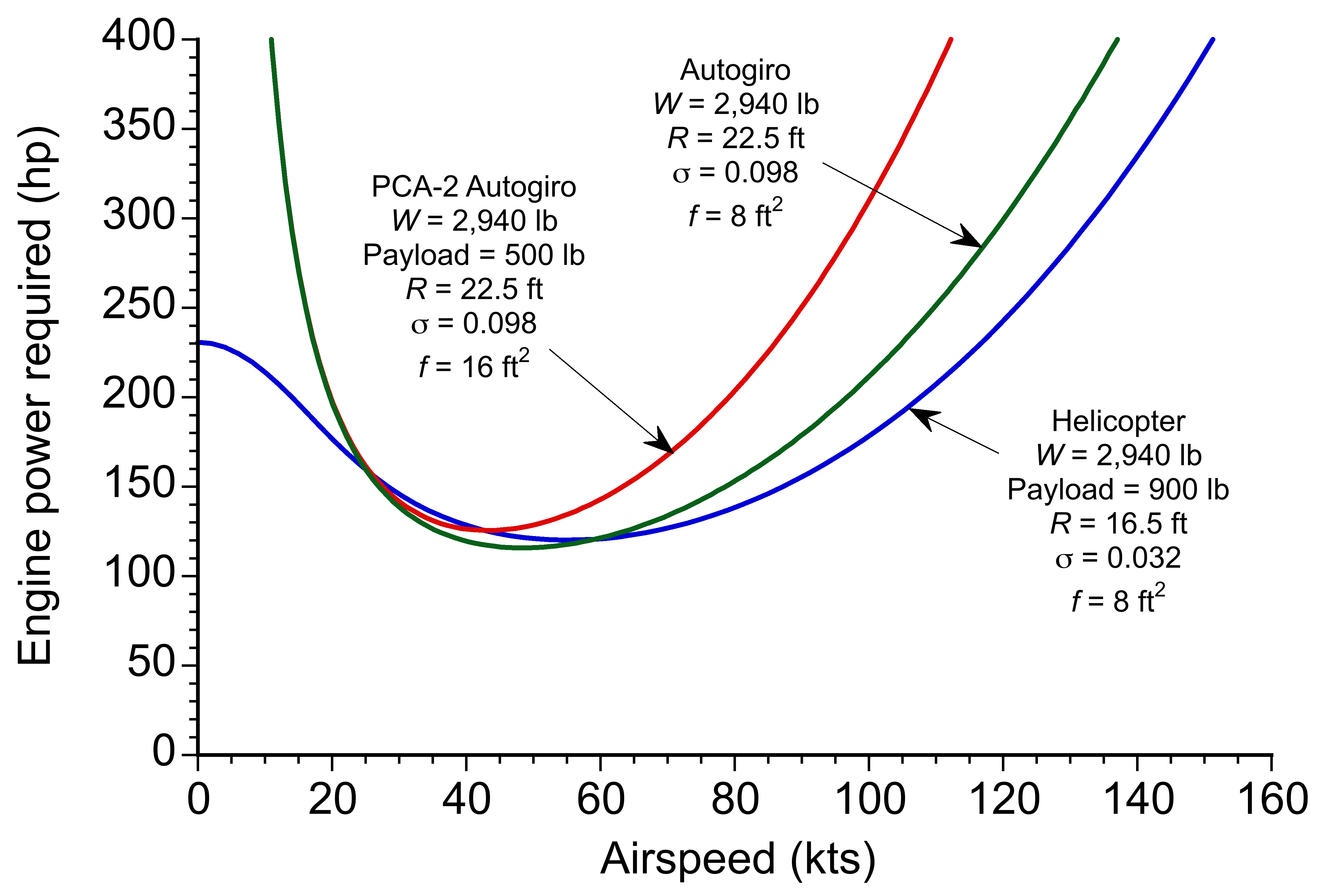
A common question in rotorcraft performance is: Which is more efficient, the helicopter or the autogiro (gyroplane)? The answer is that it depends on the flight regime and design specifics. However, when comparing the power required for flight between an autogiro and a helicopter of equivalent weight, the autogiro shows some disadvantages.
For example, in a study comparing the PCA-2 autogiro and a modern helicopter, both in the 3,000 lb gross weight class, the autogiro generally requires more power to maintain flight. This difference becomes more pronounced at higher airspeeds, where the autogiro experiences a steep rise in power requirements. This increased power demand is primarily because of two factors: 1. Higher parasitic drag from the autogiro’s airframe and rotor system, and 2. The rotor operates at higher advance ratios, which leads to significant reverse flow on the retreating side of the disk, substantially increasing rotor drag. Therefore, while autogiros benefit from less mechanical complexity and a lower empty weight, helicopters are often more aerodynamically efficient in powered forward flight, particularly at higher speeds.
Although autogiros typically require more power than helicopters at higher airspeeds, they are not inherently inefficient. With proper streamlining and drag reduction, the power requirements for an autogiro can approach those of a modern helicopter. Additionally, while early autogiros had only about half the payload capacity of a helicopter, their mechanical simplicity offers potential advantages. One significant benefit is the possibility of a lower empty weight fraction, which can translate to a higher useful load, i.e., more fuel and/or payload. Modern advances in materials and construction techniques may further reduce empty weight, improving flight performance and cost efficiency. Consequently, the autogiro, or gyroplane, remains a viable alternative to the helicopter, especially in lower weight classes where the inability to hover is less of a limitation.
Airfoils for Autogiros
Juan de la Cierva recognized the importance of airfoil selection in autogiro performance, particularly in terms of camber, aerodynamic efficiency, and pitching moment behavior. In the early stages of autogiro development, Juan de la Cierva initially employed the Eiffel 106 airfoil on the C.4. One of his later preferred choices was the Göttingen-429 airfoil, as shown in the figure below, which he favored for its “stable center of lift” across a wide range of angles of attack. This characteristic of the airfoil section helped to minimize pitching moments, which is critical for maintaining rotor stability and avoiding aeroelastic issues.
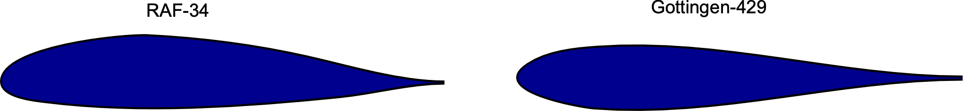
However, Cierva later became increasingly dissatisfied with the abrupt stall behavior of the Göttingen-429 when his Autogiros were flying at low airspeeds, which led him to explore alternative airfoils. For the C.19 Mk-IV, Cierva adopted the RAF-34, which featured a reflexed-camber airfoil with a relatively thick profile, characterized by a 17% thickness-to-chord ratio. For the C.30, Cierva switched airfoils again, this time to the cambered Göttingen-606. While aerodynamically promising, the airfoil produced higher pitching moments and blade twisting, which proved problematic. The low torsional stiffness of the early wood-and-fabric rotor blades led to aeroelastic instability and a crash of a C.30.
Similar challenges emerged in the U.S., where the Kellett YG-1 autogiro, which also used the Göttingen-606 with a trailing-edge tab, experienced aeroelastic issues with the rotor system. The NACA investigated these effects and attempted a solution by replacing the YG-1’s blades with a reflexed cambered airfoil called the NACA 231 series, which was developed from the NASA 230 series. However, while this airfoil improved performance at moderate airspeeds, it performed poorly under high-lift and high-speed flight conditions, proving inadequate overall in enhancing the autogiro’s performance.
Lagging Hinges
Cierva’s C.4 Autogiro featured a four-bladed rotor mounted above a fuselage taken from an Avro 504. Its high aspect ratio blades, resembling those of modern helicopters, utilized a Göttingen 429 airfoil. A Le Rhône engine-powered propeller provided thrust. Cierva retained conventional fixed-wing control surfaces (ailerons, elevator, rudder) to counteract the rotor’s natural tilt and forces on the machine. While not ideal, this solution sufficed until later designs introduced a tilting rotor shaft concept for direct rotor control. Later, autogiros incorporated rotor control by tilting the rotor disk on a gimbal or using cyclic pitch mechanisms. The C.4 successfully flew in a controlled, straight-line flight on January 9, 1923, covering about 200 meters (656 feet). The flapping hinge allowed each blade to respond to aerodynamic loads independently, reaching an equilibrium where angle-of-attack variations balanced dynamic pressure changes from asymmetric flow. This also caused the rotor disk to tilt backward, giving it a natural angle of attack, and slightly to the right (for counterclockwise rotation) due to the effects of blade coning under lift forces.
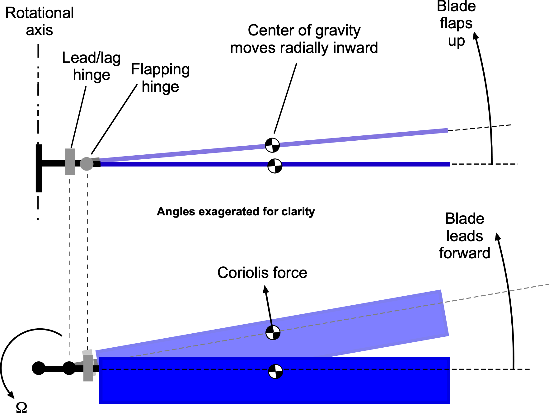
In Cierva’s early, lightly loaded designs, in-plane forces were managed by interconnecting wires between blades, resisting lag and lead motion. However, his early Autogiros suffered from a “whipping action” from Coriolis effects. As his machines grew larger and heavier, drag and Coriolis forces increased cyclic in-plane stresses at the blade root, leading to structural overloads and fatigue damage. Despite Cierva’s initial resistance because of weight concerns, a blade failure and subsequent grounding of all Cierva Autogiros convinced him of the necessity of a lead-lag hinge. He implemented this solution in the C.7, restoring airworthiness and advancing the design to the C.8. Combining flapping and lead-lag hinges was a crucial step toward the fully articulated rotor hub, which is now standard in most helicopters.
Giving Better Control
In 1934, Peck[23] conducted landing tests with the autogiro to help quantify the poor roll control response that pilots found when autogiros with conventional airplane control surfaces flew at low airspeeds. Because the autogiro could be landed at almost zero ground speed, especially into the wind, the ineffectiveness of the ailerons under these conditions was a severe deficiency in the machine’s handling qualities, resulting in several crashes. This gave autogiros a less-than-desirable reputation amongst pilots, and it was clear that the problem needed to be rectified by using some form of direct rotor control.
In 1931, Cierva introduced the directly orientable rotor control. This “rocking head” design placed the rotor system and its main shaft on a pivoting joint or gimbal. It solved the flight control problem by allowing the entire rotor disk to be tilted in any direction, thereby inclining the rotor thrust vector to give forces and moments on the aircraft. This innovation permitted Cierva to dispense with the ailerons on the stub wings, as well as the elevator, because the rotor itself was now capable of controlling both roll and pitch. However, the rudder was still retained for directional control.
In 1932, this rocking-head design was tested on a C.19, which had no conventional airplane features except for a vertical tail and a rudder. A “hanging stick” from the rotor hub to the cockpit gave the pilot reasonable control authority and relatively light control forces in both roll and pitch. The device quickly became the new standard and was incorporated into all Cierva Autogiros manufactured after 1932, including the C.30, one of the most famous and widely used autogiros, as shown in the figure below. Nearly 200 were built in Britain, the U.S., and France. However, significant rotor vibrations were transmitted through the pilot’s control stick, making it tiring to fly for longer flights.
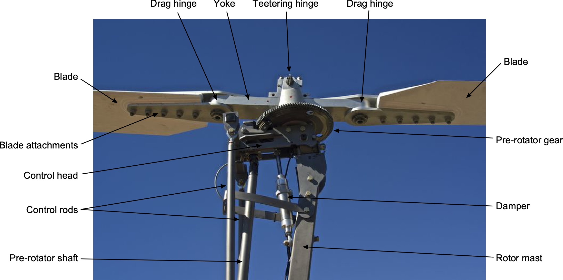
On modern sport autogiros and gyroplanes, the essence of Cierva’s tilting shaft design remains, as illustrated in the figure below, which enables the pilot to control the aircraft by adjusting the orientation of the rotor disk plane. On these machines, the rotor blades feature a teetering hub design, allowing them to flap about a central hinge on the rotational axis. The rotor mast or head is mounted to tilt fore and aft and left and right, using two pins connected via a gimbal or universal joint, which enables the head to tilt to any orientation. The rotor head is directly connected to the pilot’s control stick via control rods. When the pilot moves the stick forward, backward, or side-to-side, the rotor disk plane tilts in the corresponding direction, providing longitudinal (pitch) and lateral (roll) control. After a control input, the rotor blades will flap quickly about the teeter hinge to align themselves in a plane perpendicular to the rotor shaft.
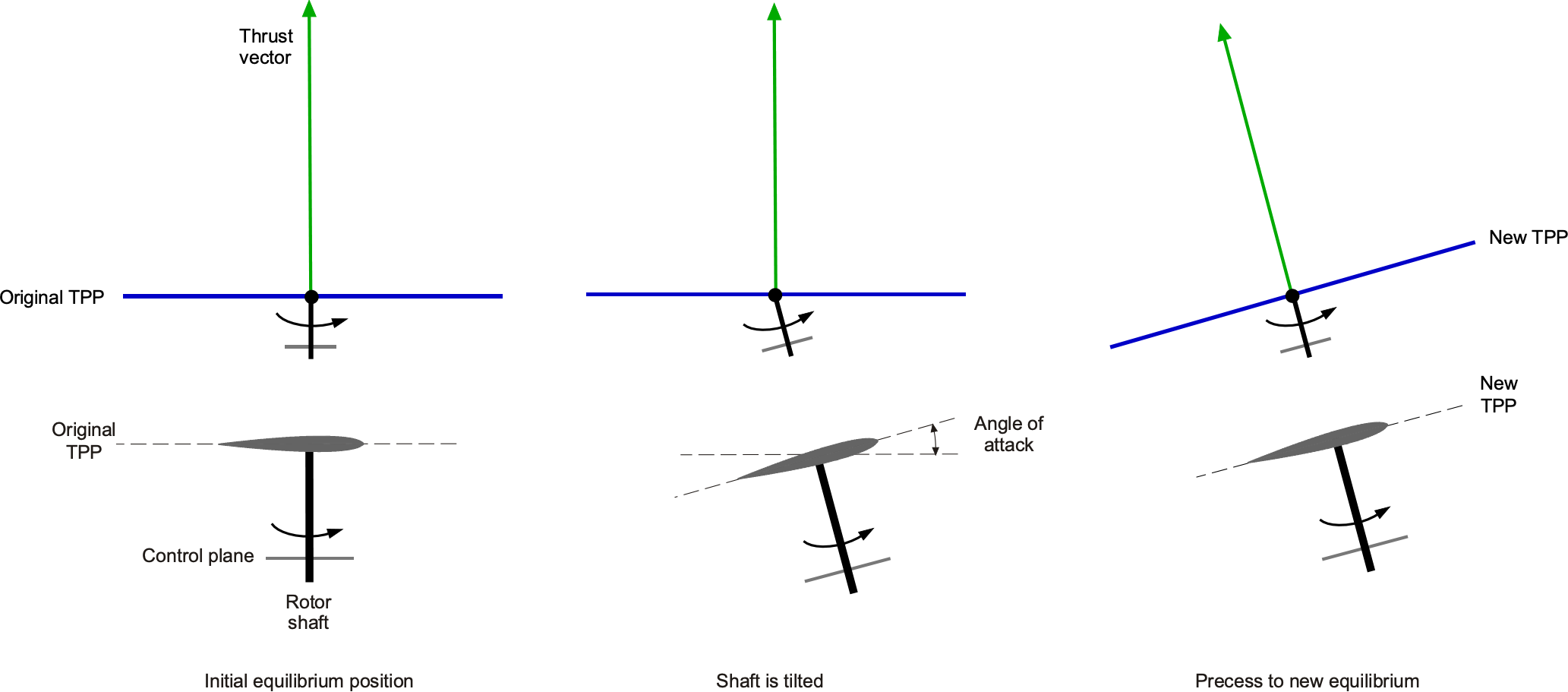
This tilting shaft design has a fixed blade pitch set at the best angle for efficient autorotation, and the blades are free to flap around the teeter hinge in response to changing aerodynamic forces. The tilting of the rotor shaft produces a change in blade pitch with respect to the original orientation of the tip-path-plane (TPP). As a result, a one-per-revolution cyclic variation in blade lift is produced, as summarized in the figure below. This lift creates blade flapping and begins to precess the TPP. The rotor plane, therefore, will align itself so that it once again becomes perpendicular to the rotor shaft, which occurs relatively quickly, certainly within one rotor revolution.
This system enables the pilot to reorient the lift vector, generating a pitching or rolling moment that alters the aircraft’s attitude and direction of flight. It is mechanically simple and highly effective for the relatively low-speed, lightly loaded flight regime of sport autogiros and gyroplanes. Because the rotor operates in autorotation, there is no need for collective pitch control or a swashplate, which simplifies construction, reduces weight, and increases mechanical reliability while offering responsive flight controls and good flight characteristics.
Drag hinges are used in some gyroplanes to allow the rotor blades to lead and lag slightly forward and backward in the plane of rotation. These hinges reduce in-plane stresses caused by Coriolis forces and unsteady aerodynamic loading during flight. However, many traditional or lightweight gyroplanes use simpler teetering rotor systems without lead-lag hinges, relying instead on the rotor system’s inherent structural flexibility and damping to accommodate in-plane motion. Lead-lag hinges are used on larger and heavier gyroplanes where there are inevitably higher loads on the rotor system.
Dampers are commonly used in tilting rotor head designs to smooth out control inputs and flight behavior, thereby improving handling characteristics. These dampers, often hydraulic or elastomeric, are positioned between the rotor hub and the control linkages. In addition, they help reduce the pilot’s workload by filtering out the primary vibrations transmitted from the rotor system to the airframe. Nevertheless, the control forces of such systems tend to be relatively high compared to most airplanes and helicopters. Just as with the C.30, the rotor vibrations transmitted through the control system can be annoying and tiring for the pilot.
While most smaller gyroplanes utilize a tilting rotor head for control, larger and heavier designs almost certainly require a swashplate system to enable cyclic pitch control of the rotor blades. In these gyroplanes, the swashplate adjusts the pitch of each rotor blade as it rotates, causing the rotor to change its orientation, similar to how flight control is achieved in helicopters. This setup can provide more precise handling and much smoother flight characteristics, and is needed for gyroplanes designed for jump takeoffs. Although more mechanically complex than the standard tilting-head approach, swashplate-equipped autogyros and gyroplanes can enhance performance, control responsiveness, and widen the aircraft’s operational flight envelope.
Jump and Towering Takeoffs
In 1929, Juan de la Cierva first proposed a means of equipping his Autogiros with vertical takeoff capability. The concept was initially tested on a version of the Weir W-3 autogiro, introducing two key advancements: a lightweight transmission that allowed the rotor to be clutched to the engine and spun up to a higher-than-normal rotational speed on the ground, and a redesigned hub with blade pitch-change capability. After numerous refinements, an innovative kinematic blade pitch-lag coupling mechanism was developed, forming the Cierva-Weir “autodynamic” rotor.
This system worked by overspeeding the rotor while on the ground, causing the blades to engage mechanical stops, which reduced their pitch to a low (zero-thrust) setting via the coupling device. In this state, the rotor generated minimal lift. Upon declutching from the engine, the blades snapped back to their original pitch, producing a sudden surge of lift that propelled the autogiro into a rapid “jump” takeoff. This type of takeoff resulted partly from the stored kinetic energy in the rotor at high rotor speeds and the aerodynamic benefits associated with rapid blade pitch changes. The sudden shift in pitch induced a lag in inflow development through the rotor, creating a transient thrust overshoot, and applying full engine power after the initial jump accelerated the machine into forward flight, where the rotational speed stabilized at its normal flight value, allowing the autogiro to transition smoothly into cruise.
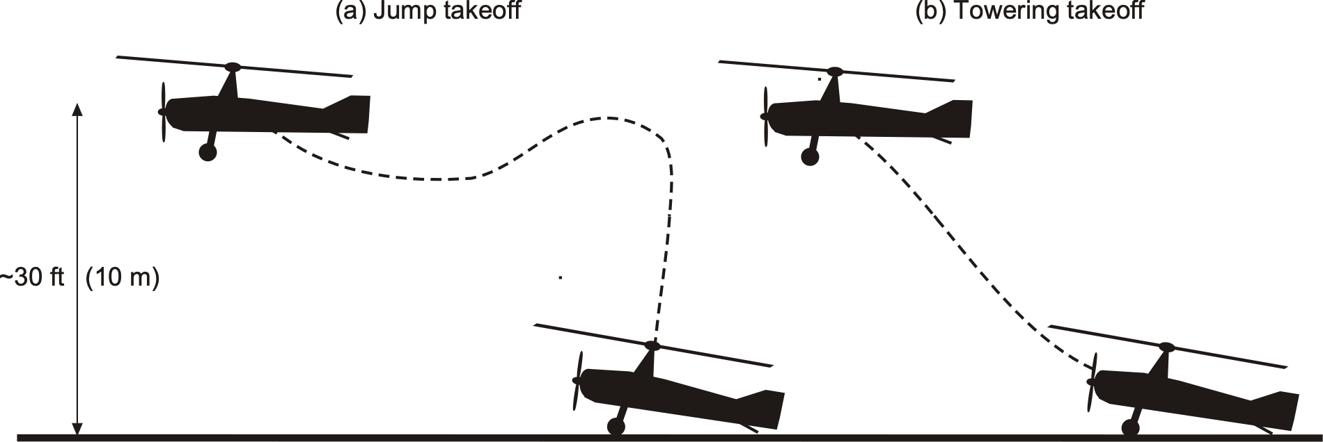
However, there was always some loss of altitude with this jump takeoff technique; the aerodynamic drag from the unpowered blades slows down the rotor speed and contributes to a decrease in its initial dynamic thrust overshoot. Because the rotor also had a substantial backward tilt to aid in normal autorotation, there was a tendency for it to jump off slightly backward. This issue increased the overall difficulty of the maneuver for the pilot. Good piloting technique, however, made the vertical jump takeoff technique consistently successful, and the autogiro often rose quickly to more than 30 ft (10 m) into the air. The autodynamic rotor system was installed on a modified C.30 and was demonstrated successfully in 1935.
Raoul Hafner developed a much more advanced jump takeoff system for his AR.III autogiro[24] in 1935. His fixed-hub, three-armed “spider” blade control system enabled continuous blade pitch variation with cyclic and collective control. Mounted atop the rotor, the spider was actuated by a control rod within the hollow rotor shaft, offering a technically superior alternative to the Cierva-Weir “binary” pitch-change system. To take off, the pilot oversped the rotor in a flat pitch while holding the machine on brakes, then rapidly applied collective pitch while simultaneously de-clutching the rotor, accelerating the engine to full power, and applying forward cyclic pitch. This system allowed for precise “towering” takeoffs with minimal altitude loss as rotor speed decayed to its normal autorotational value. Additionally, the spider hub enabled more controlled landings, giving the autogiro takeoff and landing capabilities comparable to those obtained with future helicopters.
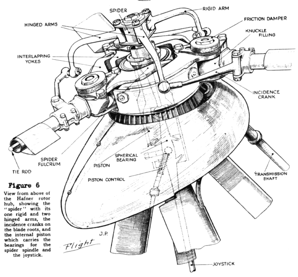
In the U.S., the Autogiro Company of America (i.e., Pitcairn and Kellett) also pursued blade pitch control to enhance the autogiro’s performance. Starting in 1933, Pitcairn introduced improvements to the Cierva rotor system, earning the Collier Trophy in 1931 for his contributions. The American jump takeoff system, first tested on the Pitcairn PA-22 and later on the Pitcairn PA-36, operated on the same principle as the Cierva-Weir system, i.e., overspeeding the rotor followed by a sudden increase in blade pitch. As pilots gained experience, PA-36 jumps improved, with demonstrations clearing 30-foot obstacles without altitude loss. Pitcairn and Kellett later competed for funding under the Dorsey-Logan Act of 1937, which sought a “rotary-wing military aircraft” capable of vertical takeoff over a 50-foot obstacle. The PA-36 fell short and lost funding to the Platt-LePage XR-1 side-by-side rotor helicopter.
Ground & Air Resonance
Early autogiros balanced in-plane Coriolis and drag forces using interconnected wires between the blades. Additionally, flap cables prevented the blades from “drooping” when the rotor was stopped. However, Cierva found this solution unsatisfactory because of the high drag created by the wires, which reduced the aircraft’s overall performance. To address this concern, he replaced the suspension cables with support stops and introduced friction disks, like a clutch stack, at the drag hinges to dampen in-plane blade motion. He termed these “cantilevered” blades, though the name is misleading because the blades remained articulated with mechanical hinges.
While effective on lighter autogiros, these modifications led to new challenges on larger machines. Issues included lead-lag forces from Coriolis effects, high control system vibrations, large control forces, susceptibility to ground resonance, and destructive aeromechanical instability. Limited technical efforts were made to understand ground resonance, and the prevailing “trial-and-error” approach failed to resolve the issue until similar problems arose with future helicopters, often resulting in the catastrophic destruction of the machine on the ground.
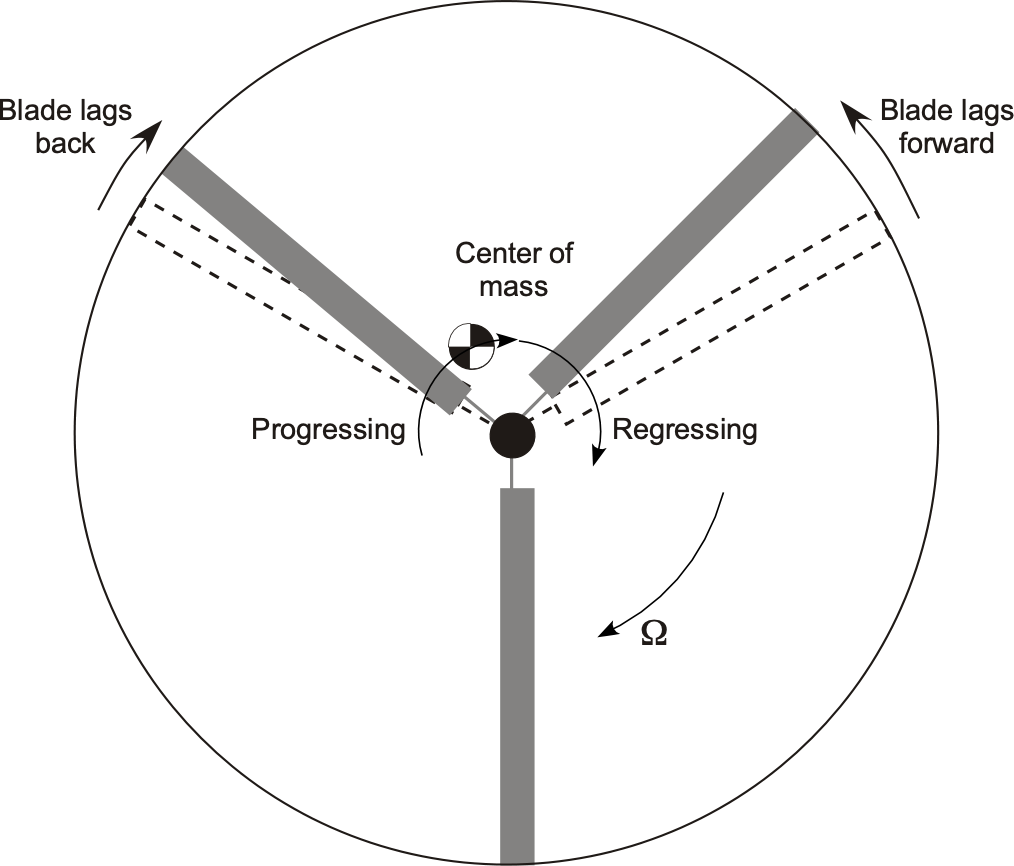
In the 1930s, NACA attempted to study ground resonance by filming autogiros from above while spinning their rotors on the ground. A second camera was mounted on the rotating hub to observe the motion of individual blades. NACA’s interest intensified after a specially instrumented autogiro in the Langley full-scale wind tunnel was destroyed due to resonance with the mounting hardware. Later, helicopters faced similar resonance issues, which were primarily mitigated by adding hydraulic dampers to in-plane blade motion and modifying undercarriage designs. Coleman & Fiegold[25] developed the first mathematical model to predict and address ground resonance. Today, lag dampers are used on most rotor systems to minimize the possibility of ground resonance.
The Demise of Autogiros
One widely cited limitation of the autogiro is its inability to hover. However, Charnov[26] suggests that factors beyond technical limitations may have contributed to its decline. While the helicopter’s ability to hover is its predominant advantage, the autogiro can still take off almost vertically using the “jump” technique and land almost vertically, especially in the wind. It is efficient at low to moderate speeds, outperforming both airplanes and helicopters in terms of economy and safety. Unlike helicopters, autogiros lack a “deadman’s curve,” making them safer at low altitudes and speeds. However, early accidents involving inexperienced pilots gave the autogiro a poor reputation; however, flight control was later improved with the introduction of directly orientable rotors.
Despite its low-speed efficiency, the autogiro could not match the speed of contemporary airplanes because of rotor limitations and its high parasitic drag, which was an artifact of the airframe’s relatively bulky and unstreamlined shape. Efforts to streamline later models and reduce rotor profile drag, such as eliminating bracing wires, helped but did not overcome this limitation. Additionally, most autogiros were single or dual-seaters, whereas airplanes of similar weight and power carried four or more passengers at a lower cost. Scaling up autogiros also introduced ground resonance and structural challenges that were not fully understood at the time.
While well-engineered to basic standards, autogiros continued to experience mechanical failures due to high cyclic stresses on rotating components. However, this was not unique to autogiros, as the structural analysis and life assessment of all aircraft were still in their infancy. Designers steadily improved the rotor’s reliability; later models were robust and dependable. By the early 1930s, helicopter pioneers, essentially working independently of autogiro developers, realized that the autogiro had resolved many rotorcraft control challenges, accelerating helicopter progress and soon diminishing interest in the autogiro.
The death of Juan de la Cierva in December 1936 at age 41 in the crash of a DC-2 airplane dealt a significant blow to future autogiro developments. Shortly thereafter, the British government attempted to consolidate rotary-wing research by merging the Cierva and Hafner companies; however, this effort ultimately failed. Raoul Hafner viewed the autogiro as an interim step toward helicopters, while Cierva had seen it as the future of rotor-borne flight. Raoul Hafner joined the Bristol Aeroplane Company (Helicopter Division) at the end of WWII. He then led the development of the Bristol Type 171 Sycamore, the first British production helicopter, marking the definitive shift from autogiros to helicopters. This effort soon led to the formation of Westland Helicopters, which became the primary rotorcraft manufacturer in the U.K. for the next four decades.
Meanwhile, in the U.S., the focus on rotating-wing aircraft also turned to helicopters. The Kellett XO-60, as shown in the photograph below, was the final evolution of the autogiro before it was rendered obsolete. In 1943, the Kellett Autogiro Corporation produced a single XO-60 prototype and six YO-60 pre-production models for evaluation by the U.S. Army Air Forces. However, the XO-60 could not hover, restricting its operational flexibility compared to emerging helicopter technology. Its payload capacity was also limited, and it suffered from ground resonance issues during rotor spin-up and landing.
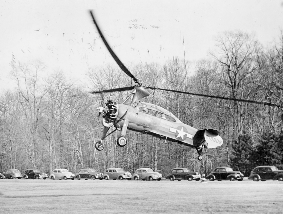
As a result, the XO-60 and the autogiro platform were retired in favor of the more versatile helicopter. Igor Sikorsky’s successful flight of the VS-300 in 1939 led to the R-4, the first mass-produced helicopter and the first used by the U.S. military. From there, American companies such as Sikorsky Aircraft, Bell Aircraft, and Hughes Helicopters drove rapid innovation, quickly establishing the United States as a global leader in helicopter development.
Renaissance of the Gyroplane?
Like many aviation concepts that were technically successful but have since been sidelined, advances in technology and new types of missions, some yet unanticipated, may revive such concepts and play a new role in the aviation spectrum. Recent developments, such as hybrid-electric propulsion, enhanced aerodynamics, and autonomous flight control, could significantly improve their performance, positioning autogiros or gyroplanes as viable options for short-range air transport. Indeed, several modern use cases are emerging. Autogiros could serve as air taxis for low-altitude intercity travel, as surveillance and patrol aircraft for law enforcement, or as affordable platforms for rural medical delivery.
One notable example of autogiro-inspired innovation was DARPA’s Heliplane project, pursued between 2006 and 2008 in collaboration with Groen Brothers Aviation. This heliplane was envisioned as a high-speed vertical takeoff and landing (VTOL) concept, aiming to merge the vertical lift benefits of helicopters with the cruise performance of fixed-wing aircraft. The goal was ambitious: a cruise speed of 400 mph (approximately 640 km/h), a range of over 1,000 miles, with vertical takeoff and landing (VTOL) capabilities, surpassing those of conventional helicopters. The design utilized a tip-jet-powered reaction-drive rotor for vertical takeoff and landing (VTOL) flight, and the rotor operated in full autorotation during forward flight. Although the vision was to develop a heliplane similar to the Fairey Rotodyne using advanced technologies, the idea depicted in the artist’s sketch below was ultimately discontinued due to technical and financial reasons. Still, the effort again underscored the potential for a gyrodyne-type rotorcraft as part of the modern aviation spectrum, if it could be developed to fully exploit its technical capabilities without being encumbered by other limitations.
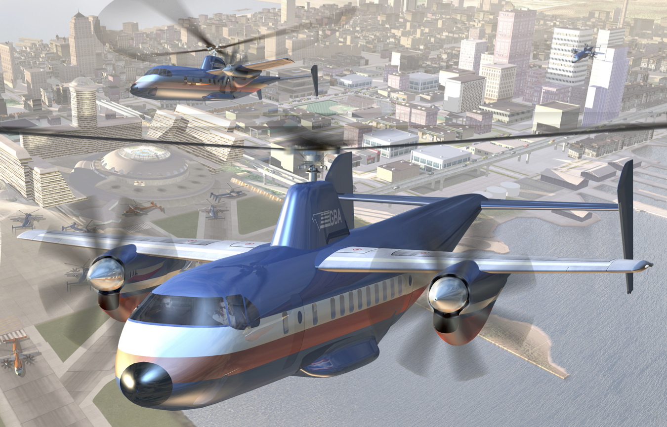
However, even if the technical issues can be overcome, many other challenges will remain. Regulatory hurdles, infrastructure needs, and limited public awareness will impede broader adoption. Integrating autorotational principles into hybrid VTOL designs could offer a compelling middle ground, combining fuel efficiency and mechanical simplicity while retaining many of the capabilities of helicopters. If these innovations succeed, the autogiro, or a modern evolution of it, may still see a renaissance, potentially playing some role in the future of aviation. Only time will tell.
Summary & Closure
This chapter has explored the unique technical characteristics of the autogiro, also known as a gyroplane, a groundbreaking rotorcraft that, a century ago, became the first powered, heavier-than-air aircraft other than a conventional airplane to achieve successful flight. The first practical rotating-wing aircraft laid the foundation for helicopter development and significantly advanced rotorcraft technology. Despite its early limitations, the autogiro’s developers pursued a methodical, step-by-step engineering approach. They introduced crucial innovations such as the articulated rotor hub with flapping and lead-lag hinges integrated with cyclic blade pitch control. Additionally, this era witnessed the emergence of fundamental theories in rotor aerodynamics, rotating blade dynamics, structural dynamics, and aeroelasticity, disciplines that remain essential to modern rotorcraft analysis and design.
Although the autogiro never achieved widespread commercial adoption, its principles continue to influence modern aircraft concepts. Fusing autogiro efficiency with helicopter versatility and fixed-wing speed could lead to the development of next-generation rotorcraft for both military and civilian applications. Advances in aerodynamics, composite materials, flight control systems, and propulsion technology offer significant opportunities to enhance gyroplane performance. However, achieving the high cruise speeds necessary for broader applications will likely require hybrid configurations incorporating lift-sharing with fixed wings. Whether the gyroplane experiences a complete renaissance remains uncertain. Still, renewed interest, supported by decades of helicopter evolution and modern computational design tools, suggests its potential may yet to be fully realized.
5-Question Self-Assessment Quickquiz
For Further Thought or Discussion
- The development of the autogiro formed the basis for the design of the modern helicopter. Yet, the autogiro has been much less of a commercial success than the helicopter. Discuss the relative merits of the aircraft versus the autogiro in terms of maximum speed capability, cruise efficiency, capital costs, and maintenance costs.
- Explain the fundamental principle of autorotation. Also, explain using blade element considerations why a rotor will autorotate at different combinations of blade pitch, rotational speed, and disk angle of attack.
- Discuss the factors that limit the low-speed flight characteristics of an autogiro. Is there any truth in the claim that the autogiro is essentially a “stall-proof” aircraft?
- Discuss the factors that limit an autogiro’s maximum forward speed capabilities. Could the autogiro be designed to have a cruise speed substantially faster than that of a helicopter?
- A helicopter uses the rotor for lifting and propulsion, whereas the autogiro uses a propeller. Regarding propulsive efficiency alone, is the helicopter or the autogiro a more efficient flight vehicle, and why?
- Consider some design issues associated with a large gyroplane concept, such as the Fairey Rotodyne. If the machine must hover, discuss the engineering and performance trade-offs related to a tip-jet-driven rotor versus a conventional shaft-driven rotor.
Other Useful Online Resources
For additional resources, autogiros, and gyroplanes, follow up on some of these online resources:
- A scarce film of the C.4 Autogiro in flight.
- History of Autogiros by the History Channel.
- How the autogiro works, a movie film from 1931.
- Golden Age Pioneers: Juan de le Cierva
- A film from 1929 with images of Juan de La Cierva and Harold Pitcairn showing and explaining the operation of the Autogiro.
- First public demonstration of the Cierva autogiro in 1936.
- Cierva C.19 demonstration at Heston Air Park, London.
- Autogyro Avro 671 Rota tested with floats in 1935
- Cierva C.30 Autogiro Ambulance!
- Avro 671 (Cierva C.30) jump takeoff demonstration in 1934.
- A 45-part video series on gyroplane history by the Gyrocopter Flying Club.
- How do Gyroplanes fly? 3-D Animation.
- Autogyros – some to consider – prices – records – safety and more!
- Gyroplane 101 EXPERT Guide Everything You Need to Know.
- A helicopter pilot tries to fly a gyroplane!
- The Airwolf of Gyroplanes – Argon GTL 915.
- It is best that the previous chapter on helicopters be studied first. This chapter is dedicated to the memory of Jay Groen, whose passion for the autogiro and gyroplane was infectious. ↵
- Azuma, A. and Yasuda, K., "Flight Performance of Rotary Seeds," Journal of Experimental Biology, 138, 1989, pp. 23–54. ↵
- Tokaty, G. A. A History and Philosophy of Fluid Mechanics, Foulis & Co., Henley-on-Thames, England, 1971. ↵
- Munk, M. M., "Model Tests on the Economy and Effectiveness of Helicopter Propellers," NACA TN 221, 1925. ↵
- Charnov, B., "The Early History of the Autogyro and Rotor Gliding," Journal of the American Helicopter Society, 2003. ↵
- Cierva, J. de la, Engineering Theory of the Autogiro, Published by the Autogiro Company of America, 1930; Cierva, J. de la, "The Autogiro," J. of the Royal Aeronautical Soc., 34 (239), 1930, pp. 902–921. ↵
- Lock, C. N. H. and Townend, "Wind Tunnel Experiments on a Model Autogiro at Small Angles of Incidence," ARC R & M 1154, 1928. ↵
- Glauert, H., "A General Theory of the Autogiro," ARC R & M 1111, 1926. Glauert, H., "A General Theory of the Autogiro," Journal of the Royal Aeronautical Society, 31 (198), pp. 483–508, 1927. ↵
- Cierva, J. de la, "A letter to RAeS with comments on the paper presented by H. Glauert on 20 January 1927," Journal of the Royal Aeronautical Society, 31 (198), 1927, pp.505–506. ↵
- Continued efforts to rediscover and digitize historical reports and other documents on autogiros, initiated by Bruce Charnov of Hofstra University, will help to ensure this knowledge is not forgotten. See: Charnov, B., From Autogiro to Gyroplane: The Amazing Survival of an Aviation Technology, Praeger Publishers, 2003. ↵
- Such as propellers and wind turbines. ↵
- Gustafson, F. B., "A History of NACA/NASA Rotating-Wing Aircraft Research, 1915–1970," 1971, Limited-Edition Reprint (VF-70) from Vertiflite, American Helicopter Soc., Alexandria, VA. ↵
- Wheatley, J. B., "Lift and Drag Characteristics and Gliding Performance of an Autogiro as Determined In Flight," NACA Report No. 434, 1933. ↵
- Wheatley, J. B. and Hood, M. J., "Full-Scale Wind Tunnel Tests of a PCA-2 Autogiro Rotor," NACA Report No. 515, 1934. ↵
- Wheatley, J. B. 1934. "The Aerodynamic Analysis of the Gyroplane Rotating-Wing System," NACA Technical Note No. 492, 1934, and Wheatley, J. B. 1935. "An Aerodynamic Analysis of the Autogiro Rotor With a Comparison Between Calculated and Experimental Results," NACA Report 487. ↵
- Bailey, F. J., "A Simplified Theoretical Method of Determining the Characteristics of a Lifting Rotor in Forward Flight," NACA Report 716, 1941. ↵
- Glauert, H., "A General Theory of the Autogiro," ARC R & M 1111, 1926, and Glauert, H., "A General Theory of the Autogiro," J. of the Royal Aeronautical Soc., 31 (198), 1927, pp. 483–508, and Lock, C. N. H. 1928. "Further Development of Autogiro Theory, Parts I & II," ARC R & M 1127, 1928. ↵
- Gustafson, F. B., "A History of NACA/NASA Rotating-Wing Aircraft Research, 1915–1970," 1971, Limited-Edition Reprint (VF-70) from Vertiflite, American Helicopter Soc., Alexandria, VA. ↵
- Houston, S., and Padfield, G., "Autogyro Flight Dynamics Modelling and Simulation," The Aeronautical Journal, 2005. ↵
- Houston, S., and Thomson, D., "On the Modelling of Gyroplane Flight dynamics," Progress in Aerospace Sciences, Vol. 88, January 2017, pp. 43–58 ↵
- This is simply a sign convention. ↵
- Wheatley, J. B., "Lift and Drag Characteristics and Gliding Performance of an Autogiro as Determined In Flight," NACA Report No. 434, 1933, and Hufton, P. A., Woodward-Nutt, A. E., Bigg, F. J., and Beavan, J. A., "General Investigation in the Characteristics of the C.30 Autogiro," ARC R & M 1859, 1939. ↵
- Peck, W. C., "Landing Characteristics of an Autogiro," NACA Technical Note No. 508, 1934. ↵
- Hafner, R., "The Hafner Gyroplane," Journal of the Royal Aeronautical Society, 42, pp. 109–158, 1938. ↵
- Coleman, R. P. and Feingold, A. M., "Theory of Self-Excited Mechanical Oscillations of Helicopter Rotors With Hinged Blades," NACA Report 1351, 1958. ↵
- Charnov, B., From Autogiro to Gyroplane: The Amazing Survival of an Aviation Technology, Praeger Publishers, 2003. ↵
