8 Anatomy of Aircraft & Spacecraft
Introduction
The world of flight vehicles encompasses a vast range of designs, from small private aircraft to massive commercial airliners, and even spacecraft that travel beyond Earth’s atmosphere. Despite their differences, most aircraft share fundamental structural components, including a fuselage, wings, tail surfaces, control surfaces, powerplant(s), and undercarriage. As aircraft grow in size and functionality, their airframe complexity increases, incorporating additional navigation, propulsion, and safety systems. Given these variations, aircraft are categorized and classified based on design complexity and operational requirements, influencing everything from engineering effort to pilot training and maintenance needs. For example, designing a commercial airliner is significantly more intricate than constructing a glider, as airliners must accommodate numerous redundant systems, high-performance engines, and stringent airworthiness standards to ensure passenger safety.
Unlike aircraft, spacecraft are not classified into standardized categories, resulting in a broad spectrum of vehicles, from small CubeSats in low Earth orbit to crewed lunar landers. While aircraft and spacecraft share some engineering principles, space vehicles face unique design challenges, including surviving the harsh conditions of space, extreme temperature variations, and navigating in zero gravity. Spacecraft are often tailored to highly specialized missions for scientific exploration, communications, or human spaceflight. Despite their differences, both aircraft and spacecraft require advanced engineering, rigorous testing, and strict safety regulations to ensure successful operations in their respective environments.
Learning Objectives
- Identify the key components of an airplane, including the fuselage, wings, tail, control surfaces, powerplant(s), and undercarriage, and understand their functions in flight.
- Understand how lift, weight (gravity), thrust, and drag interact to govern an aircraft’s flight characteristics.
- Learn how primary (ailerons, elevator, rudder) and secondary (flaps, slats, etc.) flight controls affect an airplane’s flight.
- Recognize different types of wings, tails, undercarriages, and other design elements that influence aircraft performance and aerodynamics.
- Develop a basic understanding of spacecraft, including multi-stage rockets, spaceplanes, satellites, and crewed vehicles, as well as their specialized functions in space exploration and operations.
Anatomy of Flight Vehicles
Airplane Anatomy
As shown in the figure below, for a relatively simple general aviation airplane, the airframe consists of five main groups of structural sub-assemblies, namely:
- The fuselage, i.e., the airplane’s main body, runs from nose to tail.
- The wings are the aerodynamically shaped structures designed to produce lift on the airplane, thereby overcoming its weight.
- The empennage consists of horizontal and vertical stabilizers.
- The flight control surfaces, i.e., the ailerons, elevator, rudder, and flaps, which are controlled by the pilot.
- The undercarriage, also known as the landing gear, allows the airplane to move around on the ground.
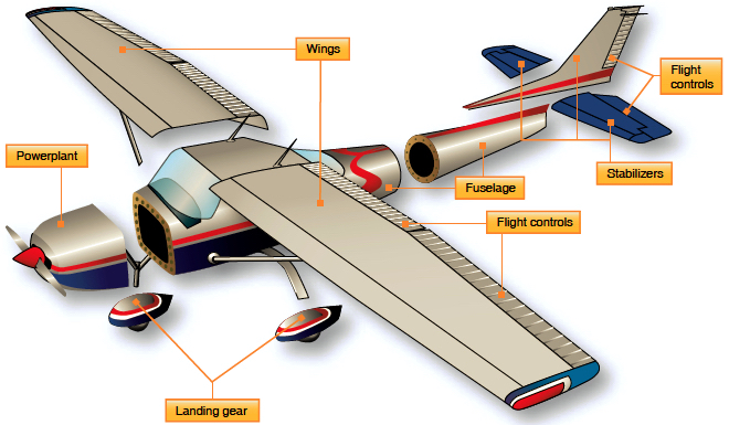
Each assembly must be designed for functionality and to carry the local loads imposed upon it, as well as the loads transferred to and from each sub-assembly. For example, the entire airframe and its components are joined using rivets, bolts, and other fasteners. In some cases, welding, adhesives, or other bonding techniques may be used as alternatives to mechanical fasteners. The engine and propeller are two primary sub-assemblies that must be connected to the airframe before the airplane can fly. The engine is placed in a suitable mount and then connected through “hard points” (stronger areas of the airframe) to the remainder of the structure. Likewise, the landing gear must locally transfer high “point loads” into the fuselage structure.
Please take a look at the more detailed image below, which also identifies the airplane’s secondary components. The wings (H & O) provide the primary lift force that sustains the airplane’s flight. The vertical stabilizer (B) gives the airplane directional (yaw) stability. The fuselage (A) is the main body of the airplane, housing the cockpit (J), engine (M), fuel, and various flight systems. The flaps (F & Q) allow the wings to sustain lift at low airspeeds and are used during takeoff and landing.
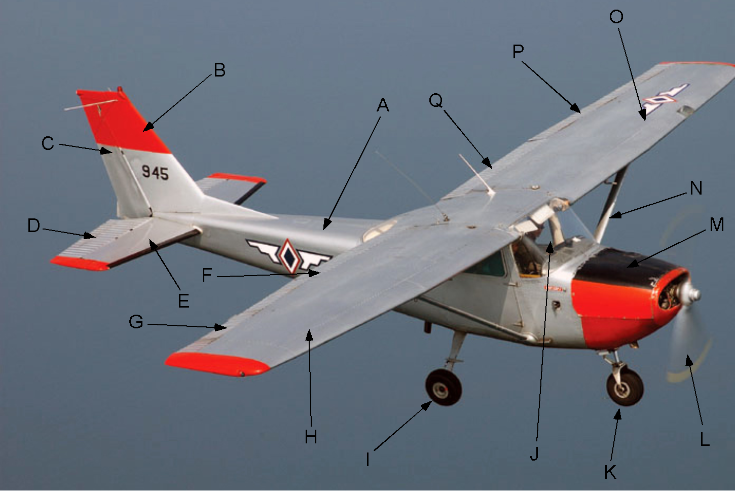
The undercarriage (I & K) consists of the wheels used to maneuver the airplane on the ground – the main gear (I) and the steerable nose gear (K). The propeller (L) provides the propulsive force to move the airplane forward; it is connected to the engine (M). The rudder (C) is used for directional (yaw) control. The ailerons (G & P) are differential flaps for roll control. The elevator (D) is used for pitch control. The horizontal stabilizer (E) provides the airplane with pitch stability. The purpose of the wing struts (N), one for each wing, is to carry tensile loads to resist wing bending from the lift forces. This video showcases the interior of a Cessna 172 and explains how all its components work together to operate effectively.
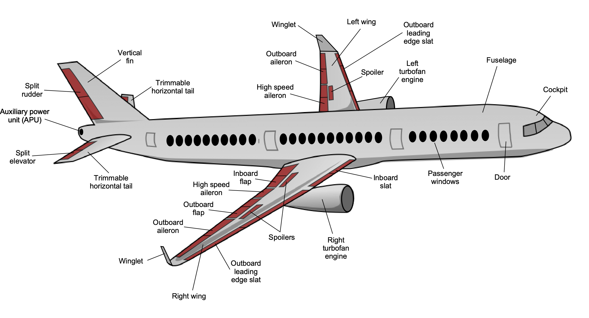
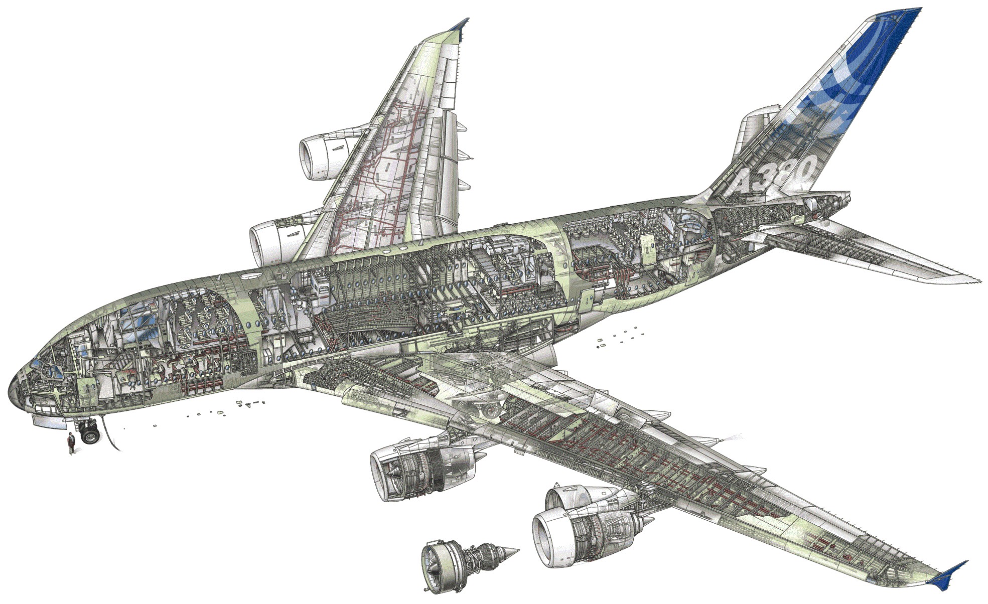
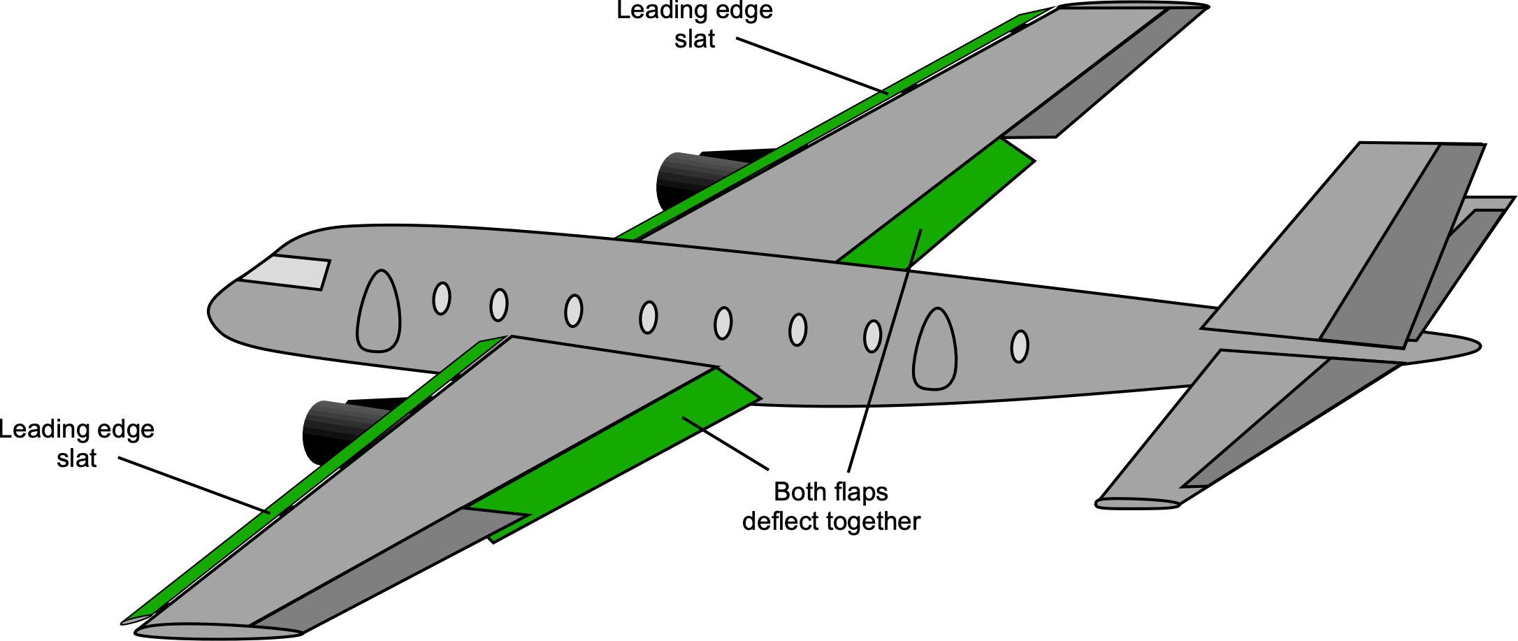
Larger and heavier airplanes have the same primary components but are typically multi-engined, resulting in more complex airframe components and systems. For example, the diagram below shows a commercial airliner that features additional components, including spoilers, leading-edge slats, multi-segment flaps, multi-segmented control surfaces for both low-speed and high-speed flight, and an all-flying, trimmable horizontal stabilizer. The fuselage is primarily designed to accommodate passengers, but it will also contain space for cargo and fuel storage tanks. The wings will contain most of the fuel required for flight. The fuselage will be pressurized to create a comfortable environment for passengers, which adds to the complexity of the airframe design and the required systems; i.e., the fuselage becomes a pressure vessel.
The structural weight of each component is also a crucial consideration, as it affects both manufacturing and operational costs. The weight of an airplane design generally grows disproportionately quickly with its increasing wingspan (i.e., the so-called “square-cube law“). For larger “jumbo” airliners, the detailed structural design becomes increasingly challenging to prevent the airframe weight from becoming excessive, thereby limiting the airplane’s functional load-carrying capability, i.e., the sum of the payload and fuel.
Wings
The primary function of the wings is to provide the needed lift to overcome the airplane’s weight. To create this lift, the wing shape is carefully designed to minimize the associated drag. The design of these components must balance conflicting requirements, such as lift, drag, stability, control, and structural efficiency, while also considering manufacturing and maintenance costs. Weight and drag are often regarded as the “killers” of aircraft performance; therefore, achieving a low airframe weight and low aerodynamic drag is crucial for good aircraft performance.
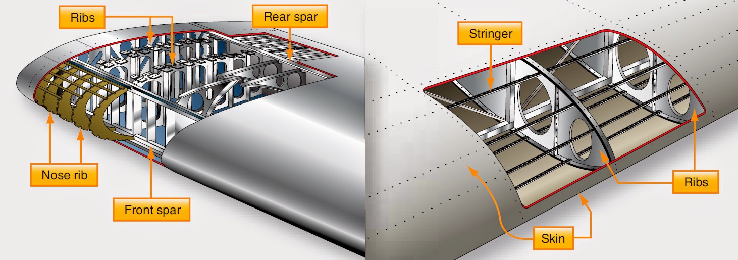
As illustrated in the figure below, wings are composed of spanwise spars and stringers to carry shear forces and bending moments imposed by the aerodynamic lift loads, with crosswise ribs that provide the wing with its basic planform and cross-sectional shape. The ribs also carry torsion (i.e., twisting) loads. Additionally, the wings may contain fuel tanks and other systems, as they are primarily hollow, shell-type structures.
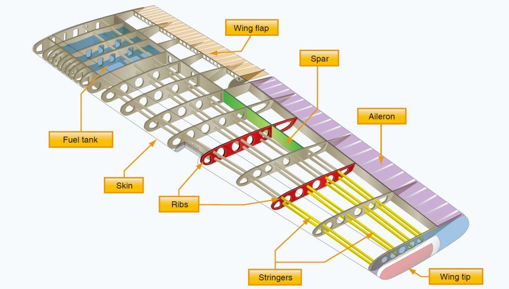
This internal wing structure is covered with a thin skin riveted to the internal structure. A rivet is an inexpensive and lightweight mechanical fastener that is bucked (i.e., deformed) into place, pinning the entire structure together. This type of airframe construction method is called a semi-monocoque stressed-skin design. Besides the ribs, the skin carries much of the torsional load imposed on the airplane’s structure by aerodynamic forces.
Like all aircraft structures, wings are designed for aerodynamic performance, light weight, strength, durability, and ease of maintenance. They are also extremely strong, capable of carrying the normally expected flight loads and a generous safety margin for unexpected loads, such as severe turbulence and heavy landing loads.
Cyclic loadings must also be considered, as they may accelerate fatigue or structural weakening, leading to the development of structural cracks or other problems that can compromise the structure over thousands of flight cycles. To this end, regions of the structure that could lead to high local stress concentrations and cracks should be minimized during design. Openings such as passenger doors, cargo doors, and windows that require structural reinforcement must be reinforced, adding weight.
The durability and repairability of the structure are also important. Regular use should not cause significant wear and tear or damage that requires frequent repair. However, if repairs are needed, they should be readily performed at almost any airport without requiring the aircraft to be returned to the factory. In this regard, metallic structures are readily repaired, whereas composite structures may require specialized facilities and tooling.
Empennage
The other aerodynamic lifting surfaces on the airplane are the horizontal and vertical tails, collectively known as the empennage. The empennage is a French word of origin, meaning “tail feathers,” i.e., as related to the flight of an arrow. The empennage may be conventional, in a “T” or “H” configuration, or a “V” tail is much less common.
The horizontal tail primarily provides the airplane with stability in pitch in the horizontal plane, i.e., in the nose-up or nose-down direction about the pitch axis. This flight surface is called a horizontal stabilizer. In addition, the horizontal tail or stabilizer may be trimmable or “all-flying,” meaning that the entire lifting surface is mounted to pivot (pitch) nose-up or nose-down to create pitching moments to balance or trim the airplane in pitch. A trimmable tail also helps minimize flight drag and reduce the control forces.
The vertical tail provides the airplane with directional stability, also known as “weathercock” stability, in the nose-left/nose-right direction in a vertical plane about the yaw axis, and is typically referred to as a vertical stabilizer. Airplanes cannot fly without horizontal and vertical tails, although flying wings have been designed to blend the main wings with the functions of the empennage. Such “flying wings” use special aft-cambered, reflexed airfoil sections to help balance the airplane’s pitching moments about its center of gravity.
Fuselage
The main body, or fuselage, of an airplane is primarily designed to carry the payload, i.e., the weight being carried that pays for the flight. For a commercial airliner, this includes the passengers and their luggage, as well as any other cargo, as shown in the figure below. While most of the fuel is carried in the wings, there may also be fuel tanks located in the fuselage, under the main cabin floor, or, in some airplanes, in the vertical tail. It should be remembered, however, that fuel is not a payload.
The shape of an airplane’s fuselage, including its length, cross-section, and other dimensions, depends on several factors, such as the number of passengers it is designed to carry. Structural strength and weight considerations are also essential design factors, along with shape and form, for achieving good aerodynamic behavior, i.e., low drag.
When a commercial airliner is at altitude, the fuselage is pressurized to an internal pressure higher than the ambient air pressure. This allows passengers to breathe normally, as if they were closer to sea level, keeping them comfortable. However, from an engineering perspective, the fuselage must be designed as a large pressure vessel, which imposes additional constraints on the structural design, especially regarding weight. Nevertheless, an unpressurized fuselage is not an option for an airliner.
Another important consideration in the aerodynamic design of the airframe is to keep any changes in cross-sectional shape relatively gradual. This reduces the flow’s tendency to separate from the surfaces, minimizing drag. For an airliner, the shape of the airframe near the wing may also be subtly modified to reduce wave drag in cruise flight at transonic flow conditions (i.e., just below the speed of sound), where shock waves begin to form.
As shown in the image below, the anatomy of a military fighter airplane differs significantly from that of an airliner. Fighter aircraft are often required to fly supersonically, so their wings are thin and more delta-shaped, with relatively short spans. The overall size and weight of the airplane must be minimized to give good airspeeds and maneuverability, which may impose extremely high loads on the structure. Instead of passengers, the airplane will carry a payload of various offensive and defensive weapons, including bombs and rockets. The design requirements may also necessitate ballistic protection for the cockpit area and critical aircraft systems.
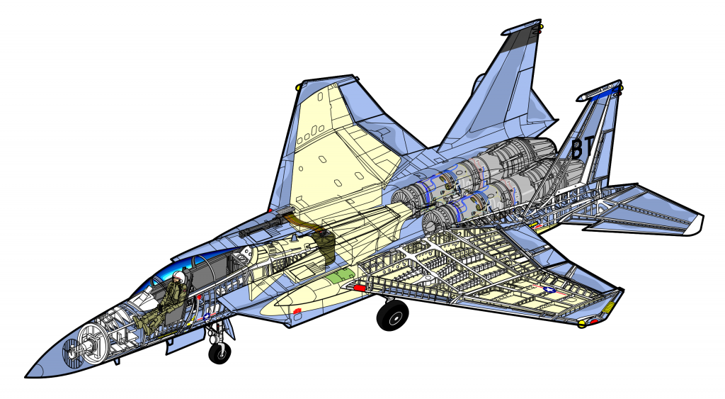
A large part of the internal structure of a fighter airplane accommodates the engine (or engines) and the needed fuel. Jettisonable external fuel tanks are often used to extend range and mission endurance because of limited internal fuel tankage and high fuel burn rates, especially when using afterburners. Relatively large and aerodynamically powerful all-flying vertical and horizontal stabilizers are often used, which help give the airplane good maneuverability. Ballistic protection may also be needed for pilots and flight-critical systems, which can significantly add to the airplane’s empty weight.
Engines & Powerplants
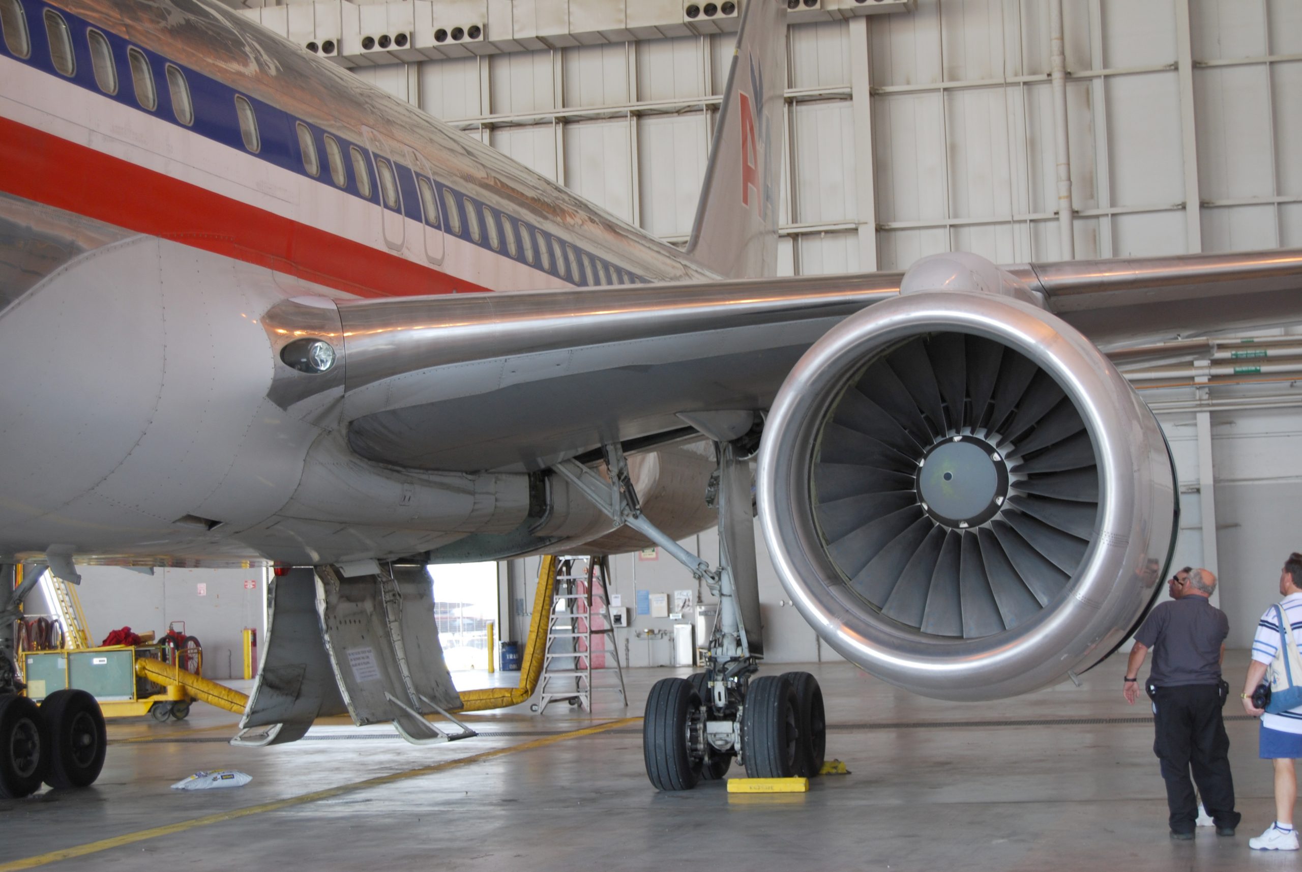
The engines on an airplane, often referred to as powerplants, provide the propulsive force, or thrust, that moves the airplane through the air and overcomes aerodynamic drag. On a modern commercial airliner, as shown in the photograph below, the engines generate substantial thrust. They have high propulsive efficiency with low specific fuel consumption, i.e., the fuel used per unit thrust. The engines also provide power for essential systems on the airplane, including hydraulic, pneumatic, and electrical, hence their more general designation as powerplants.
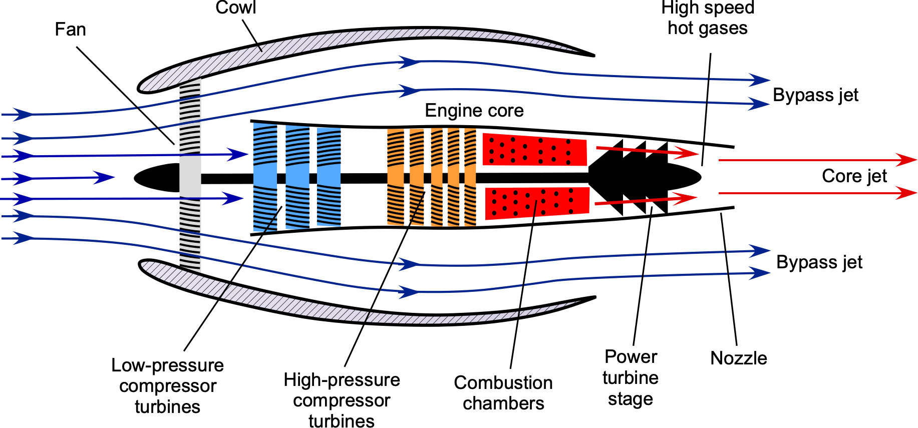
The principle of operation of a turbofan engine is shown in the figure below. The purpose of the fan is to accelerate a large mass of air through the engine while maintaining a relatively low change in flow velocity, resulting in a low exit or “jet” velocity. This approach increases thrust-producing propulsive efficiency compared to, for example, a turbojet, where thrust is produced by a very high jet velocity exiting the nozzle. The engine’s core drives the fan via a power turbine stage. At the core, the air entering the engine is compressed, then mixed with fuel, which is ignited; the resulting hot gases drive the power turbine. The jet velocity from the core is substantially higher than the bypass jet. However, the fan accounts for most of the thrust production.
However, not all commercial airplanes are powered by turbofan engines. Turboshaft engines, which drive propellers, are used in turboprop aircraft and usually power smaller commuter aircraft. Smaller airplanes, such as general aviation types, are typically powered by piston engines, which are reciprocating internal combustion engines that drive a single propeller or, in some cases, a twin-engine configuration. With few exceptions, helicopters will use one or more turboshaft engines.
An essential consideration in designing a multi-engine airplane is its ability to fly safely if one engine fails during flight, a condition known as One Engine Inoperative (OEI). In a twin-engine airplane, each engine must be powerful enough to keep the airplane flying, even though this reduces its performance. Therefore, OEI flight performance is an important design consideration for all multi-engine airplanes. This aspect is scrutinized during flight testing and certification to demonstrate that the airplane can still safely fly in OEI conditions.
Why a “plane” is not an “airplane.”
The word “plane” is often used in the lexicon in reference to an airplane. However, engineers never use the name “plane” but always “airplane” (American English), “aeroplane” (British English), or just “aircraft.” An aircraft can be anything that flies, but an airplane is a specific type of aircraft with wings that uses aerodynamic forces for flight. It is also helpful to recognize that the plural of aircraft is aircraft, not “aircrafts.” The word “aircraft” has an irregular plural form, so it functions as both singular and plural. Likewise, we use “spacecraft” (singular and plural) and never “spacecrafts.”
Forces of Flight & Flight Axes
Before describing the flight controls and their effects on an airplane, it is essential to understand the forces of flight and the definition of the axes about which the airplane moves. Four forces act on an airplane, as shown in the figure below. First, the effects of “gravity” manifest as the airplane’s weight, denoted  , which is assumed to act downward at the center of gravity. The primary aerodynamic forces on the airplane are lift, denoted by
  , which acts upward and in a direction opposite to the weight, and drag, denoted by
  , which acts parallel to the direction of flight.
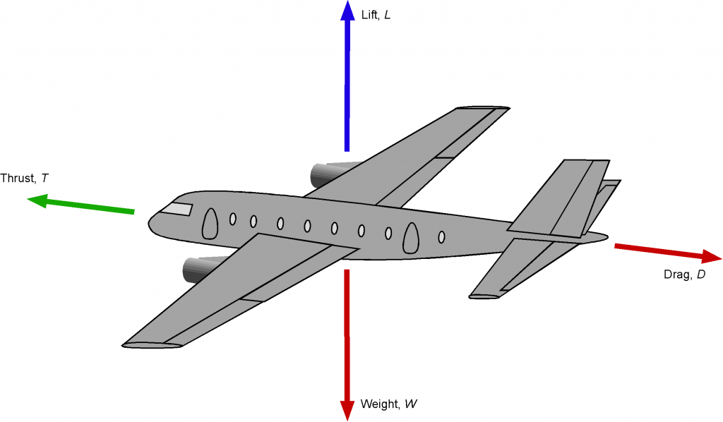
The underpinning of flight is the lift on the wings, so understanding the aerodynamic characteristics of the wings is a vital part of airplane design. Lift generation results from the net pressure forces produced on the wing surfaces. As the airflow during flight approaches the wings, it is accelerated more over the upper surfaces, resulting in lower pressure there relative to the lower surfaces. Therefore, this pressure difference between the upper and lower wing surfaces is the source of the lift force that sustains flight. However, a consequence of lift generation is always drag.
In steady, unaccelerated, equilibrium flight, which is often called trim, the lift on the airplane will be equal to its weight, and the thrust required for flight will be equal to the airplane’s drag, i.e.,
(1) 
and
(2) 
The airplane can also pitch, roll, and yaw. It will pitch about the lateral axis, roll about the longitudinal axis, and yaw about the vertical axis, as shown in the figure below. In general, moments can be produced from the pilot’s application of the flight controls about each of the three flight axes, i.e., a pitching moment,  , a rolling moment,
  , and a yawing moment,
  . The lift and drag can be assumed to act at a specific location on the wing, known as the center of pressure, where the pitching moment is zero; this position is often referred to as the neutral point.
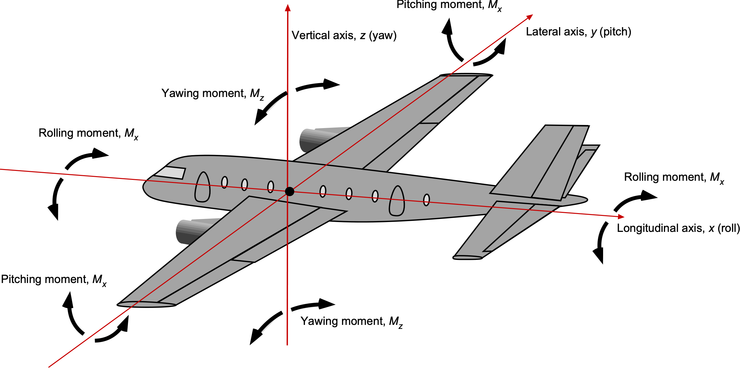
In steady-level equilibrium flight, i.e., in trim, the airplane’s net moments about its center of gravity must be zero, i.e.,
(3) 
However, the need for force and moment equilibrium is not necessarily the case in maneuvering or accelerated flight.
Note that the origin of the coordinate system used for analysis can be at any convenient point; in engineering practice, different origins may be used depending on the type of analysis. The airplane’s center of gravity is often used as a reference, although it should be noted that the center of gravity is not a fixed point and will shift slightly during flight as fuel is burned off and the airplane’s weight decreases.
Consider, for example, the airplane in the figure below. The airplane’s weight can be assumed to act at its center of gravity. For vertical force equilibrium in trim, then
(4) 
If the lift on the tail  , where
  would be less than 1, then
(5) 
or
(6) 
so
(7) 
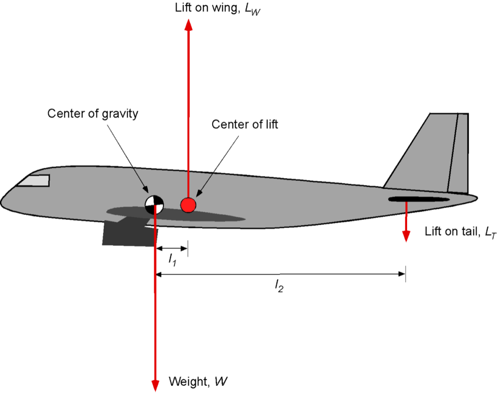
For pitching moment equilibrium in trim, then
(8) 
So, in this case, then
(9) 
Notice that as the value of  increases, i.e., the center of gravity moves further away from the center of lift, then the downward force on the tail must increase, i.e., by applying the elevator controls or trimming the tail. There is a limit to how far this distance can be allowed to move, which is one reason for constraining an airplane’s center-of-gravity envelope.
Flight Controls
The wings and empennage feature flight control surfaces, including the ailerons, elevators, and rudder, as illustrated in the figure below. The pilot controls the airplane’s flight to give it the desired flight attitude by simultaneously using the elevator, ailerons, and rudder. The skill required for coordinating the flight controls must be learned. Each type of airplane can have somewhat different flight characteristics, but the basic functionality of the flight controls is the same.
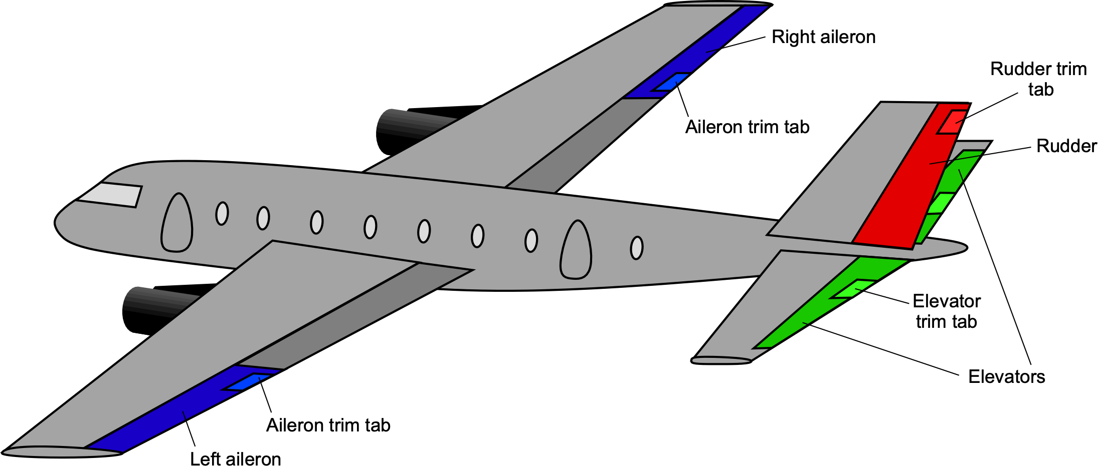
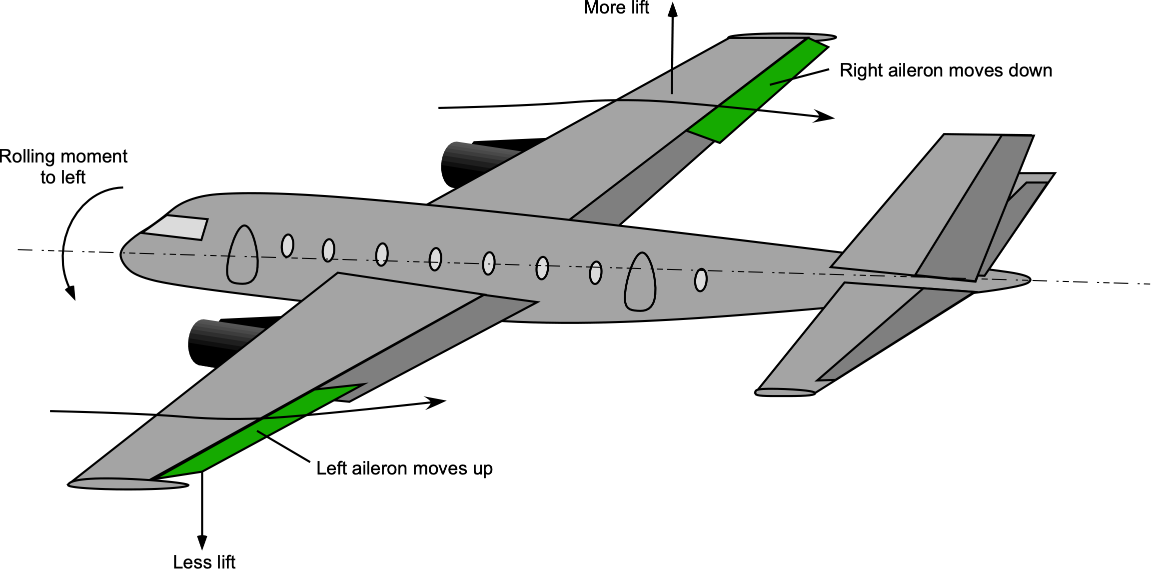
The purpose of the ailerons is to give the airplane roll control about the longitudinal axis. As shown in the figure below, the ailerons are a set of differentially operated trailing-edge wing flaps. When an aileron on one wing is deflected down, the other simultaneously deflects up, thereby producing a relative difference in the lift production on the two wings. The net result is a rolling moment in one direction or the other. Therefore, the ailerons control the airplane’s bank angle and help it turn.
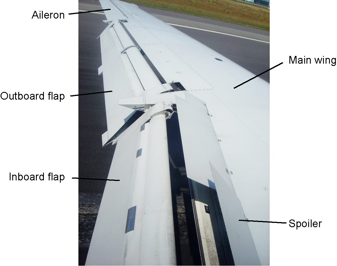
On some airplanes, particularly larger ones, there may be multiple sets of ailerons (or segmented ailerons), with one set near the wing tips and another inboard. The inner and outer sets of ailerons are used together at low flight speeds, such as takeoff and landing, to provide the airplane with better roll control; however, only the inner sets of ailerons are needed in cruise. On modern airplanes, the phasing in and out of the appropriate sets of flight controls is automatically controlled by the flight control system; i.e., the outboard and inboard segmented ailerons are phased in and out as a function of airspeed. This latter approach also helps minimize the wing’s structural bending and torsional loads associated with outboard control-surface deflections at higher airspeeds.
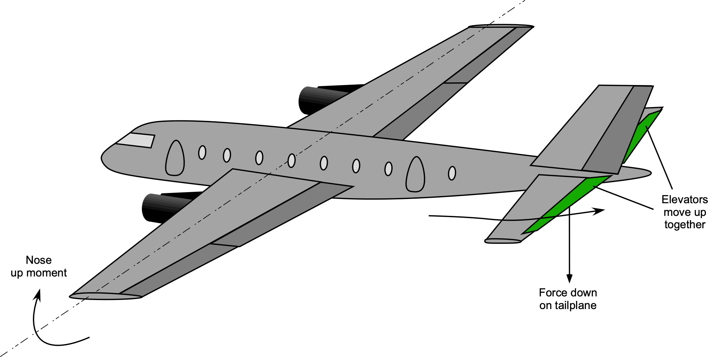
The horizontal and vertical tails also have trailing-edge flaps. On the horizontal tail, they are called elevators; on the vertical tail, they are called the rudder. Deflecting the elevators up and down (both sides move together), as shown in the figure below, increases or decreases the relative lift on the horizontal tail. The primary effect is a change in the airplane’s pitching moment about its center of gravity. Therefore, the pilot’s use of the elevator controls the airplane’s pitch attitude. The function of the trimmable tail has already been discussed.
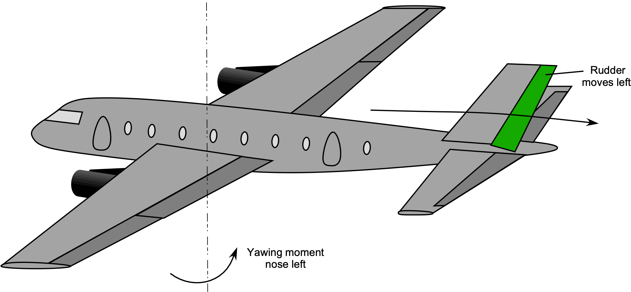
Similarly, deflecting the rudder left or right produces a yawing moment; that is, the rudder deflection results in a nose-left or nose-right response, depending on the direction of angular deflection, as shown in the figure below. Like the ailerons, the elevator and the rudder may have segmented sections, especially on larger airplanes, the activation of which is phased in or out as a function of airspeed.
Flaps & Slats
The flaps and slats on a wing enable the airplane to fly at lower airspeeds without stalling and losing lift, and are primarily used during takeoff and landing. Flaps and slats are referred to as high-lift devices. As airspeed is reduced, the wing must operate at an increasingly higher angle of attack, and the onset of stall will eventually limit lift production. Wings operate successfully without stalling only at low angles of attack to the flow. However, the deflection of the flaps and possibly slats, as shown in the figure below, allows the airplane to fly at lower airspeeds without stalling, commensurately reducing the takeoff and landing distances.
The wing shape of a commercial airliner is primarily designed for efficient aerodynamic flight at higher (transonic) airspeeds and higher altitudes, so this relatively thin wing shape tends not to function as well at low airspeeds. For this reason, flaps and slats are used for takeoff and landing. High-lift devices are crucial for larger airplanes operating at high gross weights, as they help reduce takeoff and landing distances to match the available runway lengths.
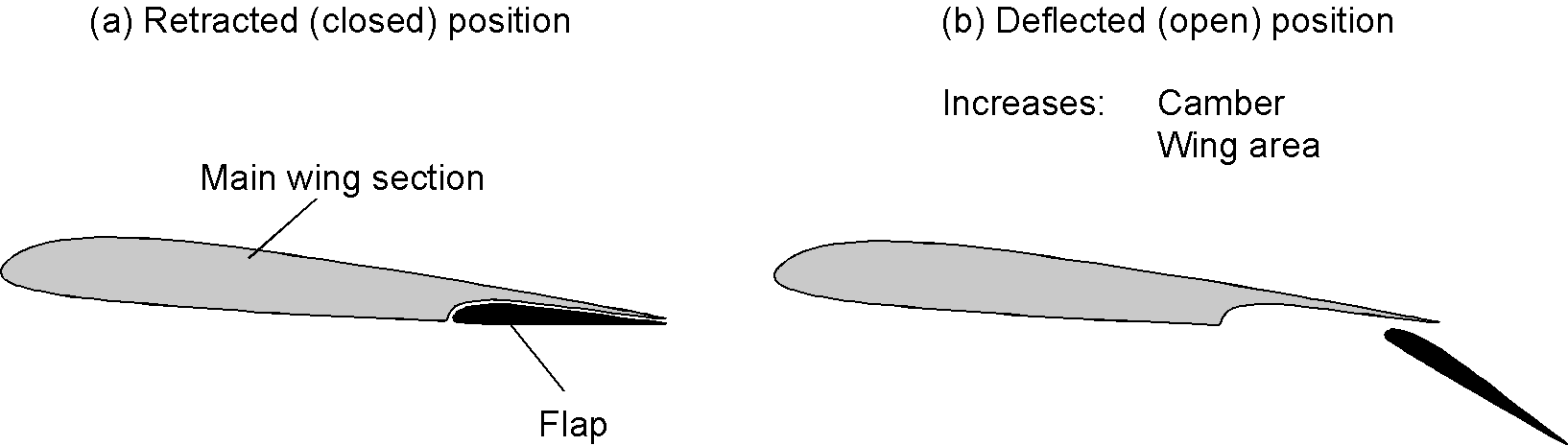
The flaps are often designed to deflect downward and rearward, as shown in the figure below. This increases the wing’s effective area and its curvature (camber). The net effect is that the wing can now operate at a lower airspeed without a tendency to stall, although the wing’s drag also increases with the flap deflection angles. Applying large flap deflections creates much drag and usually requires the pilot to apply extra thrust to maintain level flight at the same airspeed.
Flap systems may include secondary elements (e.g., double- or triple-slotted flaps) that deploy progressively in stages, as shown in the figure below. The flaps are partly extended and deflected to reduce the takeoff airspeed and distance. The airplane needs to build up airspeed quickly and does not require the high drag associated with full flap deflection. After takeoff, the flaps are progressively retracted as the airplane’s airspeed builds. A great animation of a triple-slotted flap system can be found here.
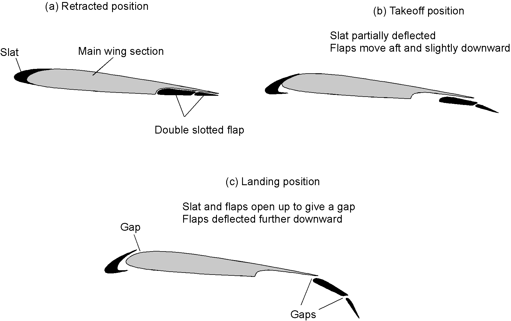
The flaps will eventually be fully deflected for landing. The pilot progressively extends them as the altitude decreases and the airplane slows to its final landing approach speed. The extra drag from full flap deflection further slows the airplane to acceptable landing airspeeds, steepening its final approach angle to the runway. This allows the pilot to control the flight path and the airplane’s descent rate during the landing approach.
The leading-edge slats also work in synchronization with the flaps. Like the trailing-edge flaps, their purpose is to delay the onset of stall, allowing the airplane to fly at lower airspeeds. The slats initially move forward and downward to increase the wing section’s camber, and when fully deployed, they open a small gap between themselves and the main wing’s leading edge. This gap between the flap segments is crucial and helps maintain the flow attached to the flap surfaces at higher flap deflection angles.
Slats are highly effective at delaying the onset of a stall on a wing and increasing lift. However, like flaps, they also increase drag somewhat and may shift the wing’s center of lift, creating a pitching moment on the airplane. For this latter reason, the slats and flaps are usually activated simultaneously to minimize any changes in pitching moments, with partway deflections being used for takeoffs and full deflections for landings. With both fully deployed slats and flaps, the airplane can typically fly at airspeeds that are nearly half what it would be without them, i.e., compared to flying in the “clean” condition with flaps and slats retracted.
Specific Flap Designs
As summarized in the figure below, there are numerous trailing-edge flap designs, each with its own advantages and disadvantages. Among the standard designs are plain flaps, which offer simplicity and moderate lift augmentation but are less effective at low airspeeds. Split flaps provide greater lift but at the cost of increased drag. In contrast, slotted flaps overcome some of these limitations by preventing flow separation and generating higher lift coefficients. Fowler flaps are renowned for their significant lift augmentation and drag reduction, but they add weight because their more mechanically complex deployment mechanism. Junkers flaps provide substantial lift augmentation; however, the external drag of the supporting mechanical structure is a concern. Gurney flaps offer a straightforward modification to enhance lift and delay stall, though their effectiveness is limited compared to other designs.
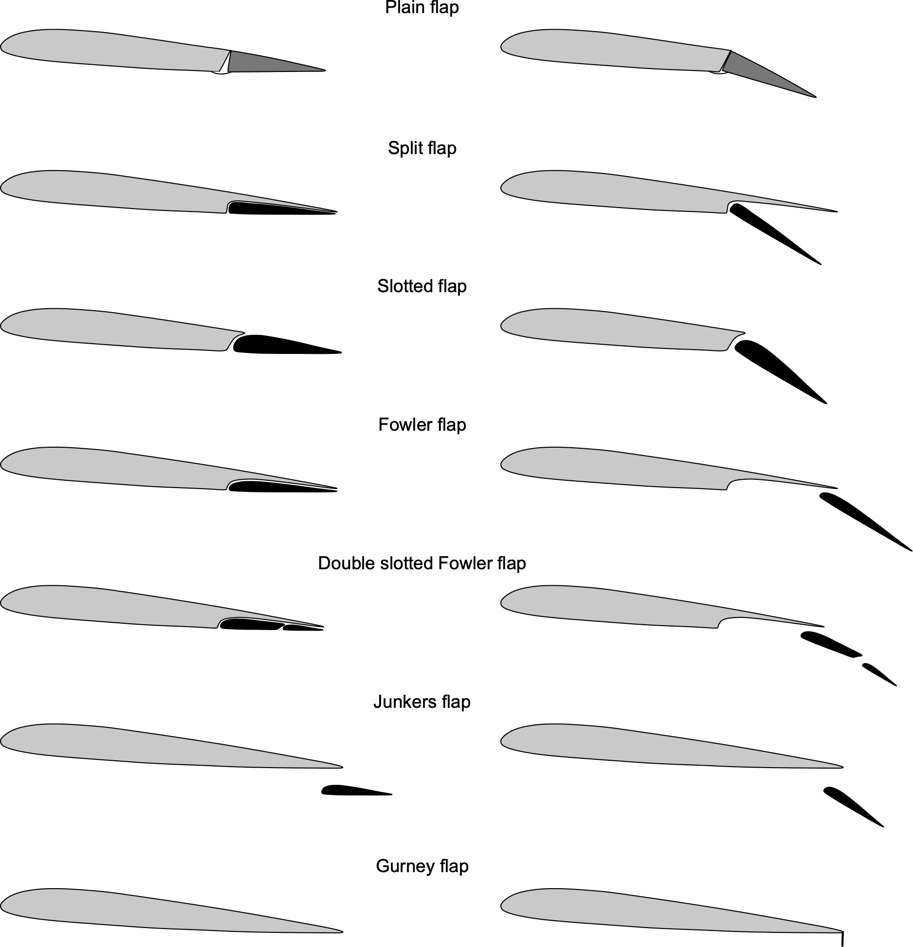
In selecting a flap design, designers must carefully balance lift augmentation, drag reduction, complexity, weight, and cost. While some designs prioritize simplicity and lightweight construction, others focus on enhancing lift and reducing drag, albeit at the expense of increased complexity and maintenance requirements. The choice of flap design ultimately depends on the aircraft’s specific performance requirements and operational envelope.
Main Wing Designs
Airplanes come in many shapes and sizes, with various combinations of main wings, tails, and undercarriage configurations. Even a cursory look at the early history of aviation reveals nearly as many different wing and tail configurations as there are airplane designs. As shown in the figure below, examples of main wings include high-, low-, and mid-mounted wings, gull wings, and various types of swept wings.
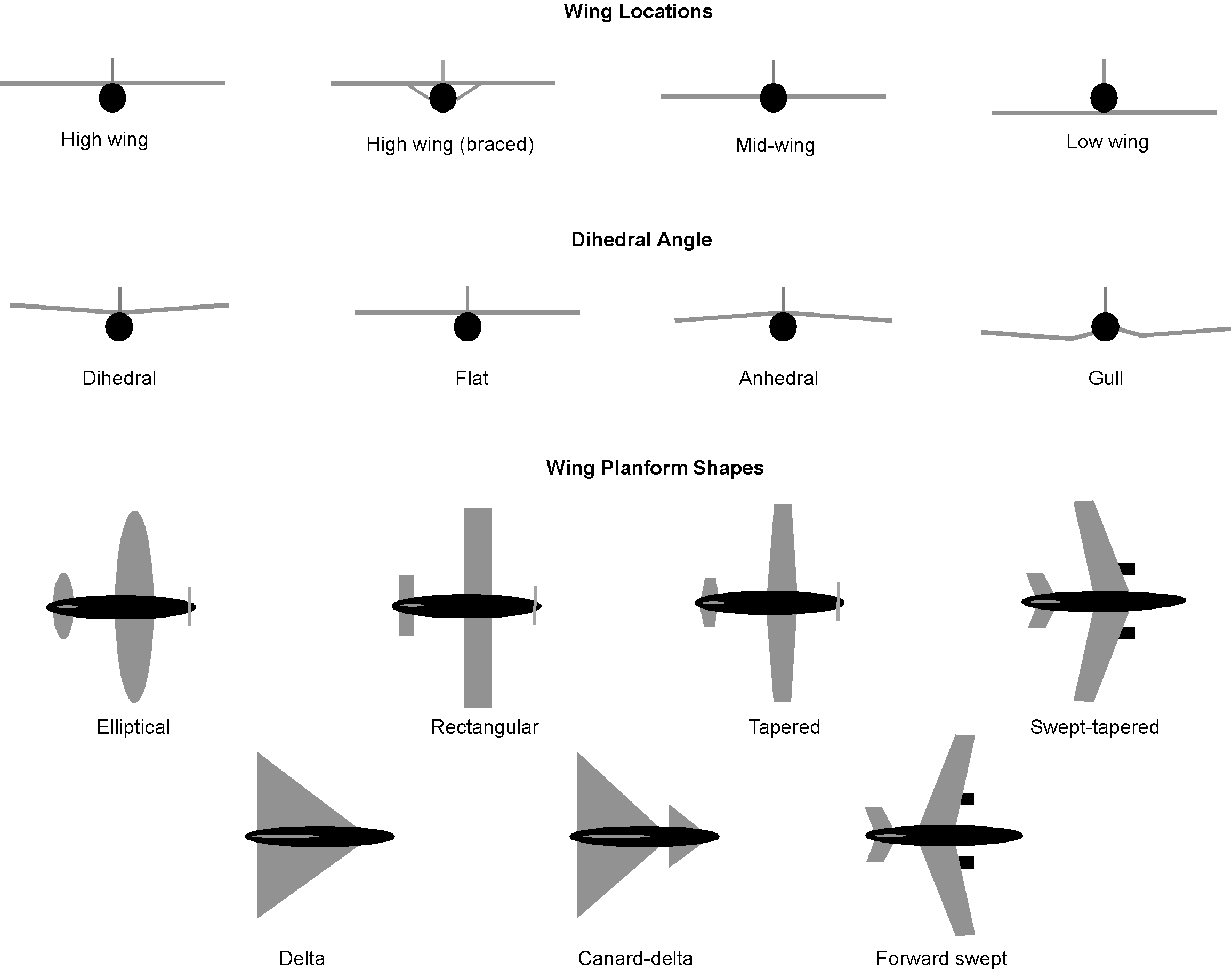
Wings can also have different planform shapes (i.e., the outline shape of the wing when viewed from above), such as rectangular, tapered, elliptical, or some other variation. Naturally, there are sound engineering reasons (in most cases) for preferring one wing shape over another. Swept wings are designed for high-speed flight, and the sweepback helps to alleviate compressibility effects and reduce drag, allowing the airplane to fly faster. However, sweeping a wing back creates other engineering concerns, so the sweepback is usually kept to a minimum. Additionally, the use of forward-swept wings is unusual because of their susceptibility to undesirable aeroelastic effects.
Wings can also be cantilevered (i.e., no external bracing with all internal structure), braced with struts and wires, and appear as monoplanes (single wings), biplanes, and even triplane configurations, as shown in the figure below. The cantilever monoplane design is the most common wing for airplanes because of its low aerodynamic drag. However, lower-performance airplanes may use braced wings because they are comparatively lighter than an entire cantilevered wing.
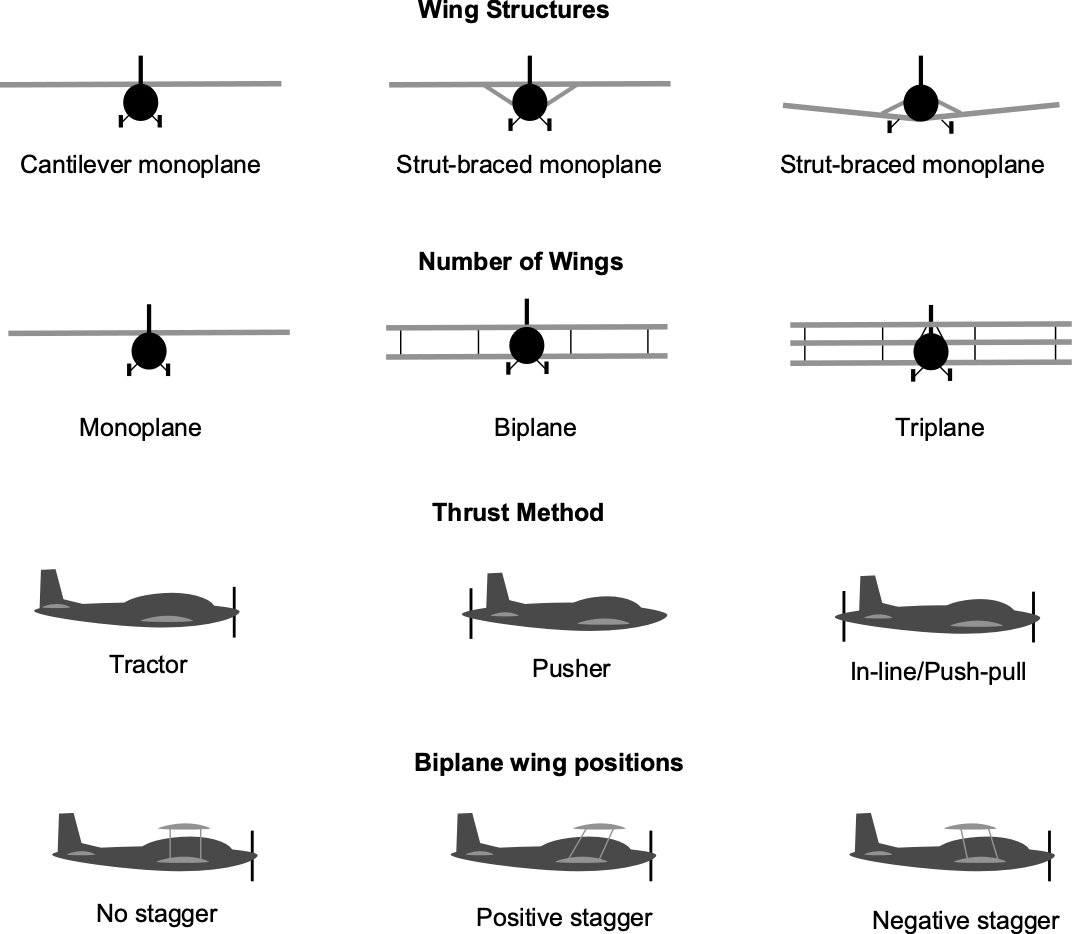
In the early days of aviation, wings were built as biplanes or triplanes, which provided the wood-and-fabric wing structures with the necessary bending and torsional strength and stiffness. However, the high aerodynamic drag of the struts and wire bracing between the wings significantly reduced the airplane’s performance, especially limiting its maximum achievable airspeeds.
The advent of aluminum alloys as a construction material soon enabled the construction of “stressed-skin” monoplanes, which gave the wings much greater strength and significantly less drag. As a result, monoplane airplanes could soon fly at much higher airspeeds. However, a problem with early monoplane wings was flutter, an aeroelastic phenomenon that can lead to a catastrophic structural failure of the wing. Designers soon learned about the flutter problem and developed design techniques to give wings the structural stiffness needed to avoid flutter.
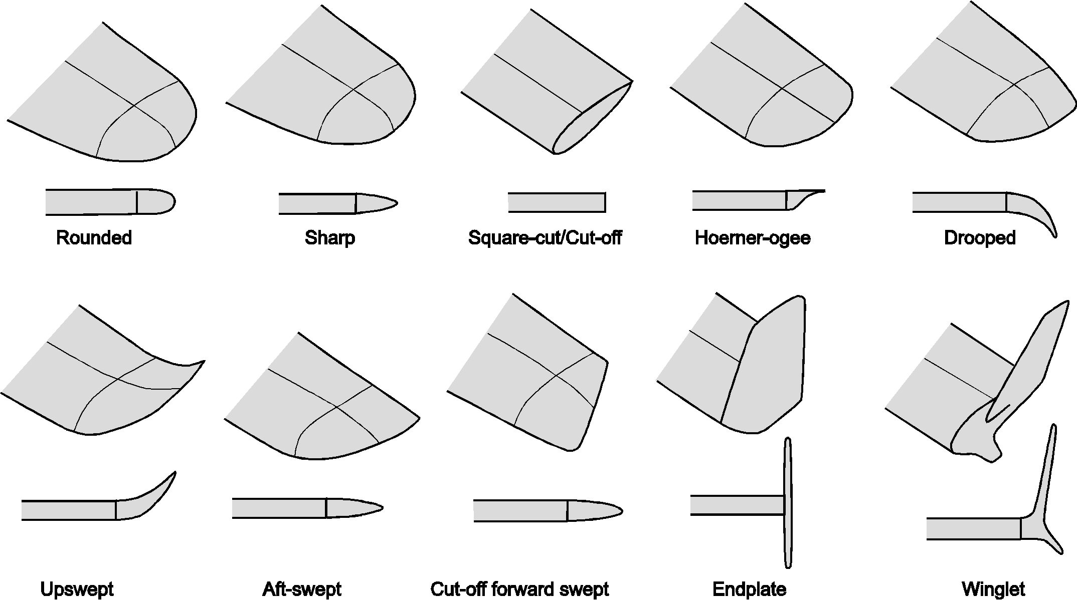
At the tips of a wing, the flow leaks around the edges and develops into a swirling flow known as a wing tip vortex, a source of drag referred to as induced drag. The detailed shape of the wing tips influences the roll-up of the tip vortices. Over the decades, various wing tip shapes have been designed to reduce induced drag, as illustrated in the figure below. One of the most common designs today is the winglet, which has been proven to reduce drag on commercial airplanes and deliver significant fuel savings throughout the aircraft’s operational life.
Tail & Empennage Designs
The tail section or empennage of an airplane can also take on different configurations, including the conventional or “standard” tail with horizontal and vertical surfaces, but also “T,” “H,” and “V” or butterfly tails, and twin-boom tails, as shown in the figure below. Remember, the purpose of the empennage is to provide the airplane with directional stability in pitch and yaw, and to allow for pitch and yaw control via the elevator and rudder, respectively.
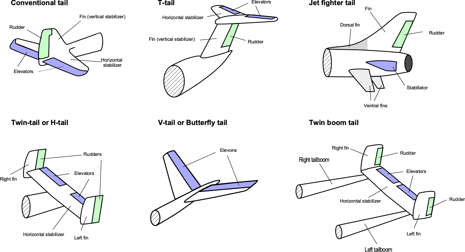
Each tail configuration has its advantages and disadvantages, but in some cases, a design may favor one type over another. For example, the V-tail, also known as a butterfly tail, has the advantage of only two lifting surfaces versus three, potentially saving weight and manufacturing costs. However, the response of the flight controls (e.g., the separate application of elevator and rudder) can become aerodynamically coupled, resulting in less distinct and separate responses for pitch, roll, and yaw. To this end, an appropriately designed flight control system must be designed to decouple the responses.
A T-tail is out of the turbulent wake of the main wing, thereby improving its aerodynamic effectiveness for a given control deflection. However, this type of design is usually structurally heavier than the conventional tail. A T-tail design has also been shown to be more prone to flutter, as attempts to reduce its weight have also led to a reduction in structural stiffness. The high torsional stiffness of the rear fuselage is also essential. Nevertheless, a T-tail configuration is common for modern airplane designs. Historically, the T-tail design has also raised some aerodynamic concerns, such as susceptibility to “deep stall” at high angles of attack, where turbulent flow from the wing blankets the tail surfaces and reduces the effectiveness of the elevator and rudder, which must be thoroughly investigated during flight testing.
In the twin-boom tail or double-tail empennage design, the aft airframe consists of two separate fuselages or “tail booms,” each with a rudder but usually connected by a single horizontal stabilizer. Although the twin-boom empennage configuration is less common today, many aircraft have been designed with it. It can be used when a conventional empennage is not possible. For example, when a propulsion system (propeller or jet) is installed at the rear of the fuselage, significant flow interference can occur between the propulsion system and the airframe. This interference can be minimized by using a twin-boom tail. Specific cargo aircraft that require rear loading or have aircraft length and/or height constraints may also utilize a twin-boom tail.
Engine Placement
Except for gliders, all airplanes have thrust-producing devices (i.e., engines or so-called powerplants) that consist of the engine (and propeller) and related accessories, such as electrical generators, hydraulic pumps, pneumatic pumps, oil pumps, and fuel pumps. The main engine types that sustain flight are reciprocating (piston) and reaction engines, such as turbofans, turbojets, and turboprops.
The history of aircraft shows that various engine placements have been used. The preference for using one engine type or engine placement over another depends on many factors, including the airplane’s purpose. Below are examples of engine placement for propeller-driven airplanes.
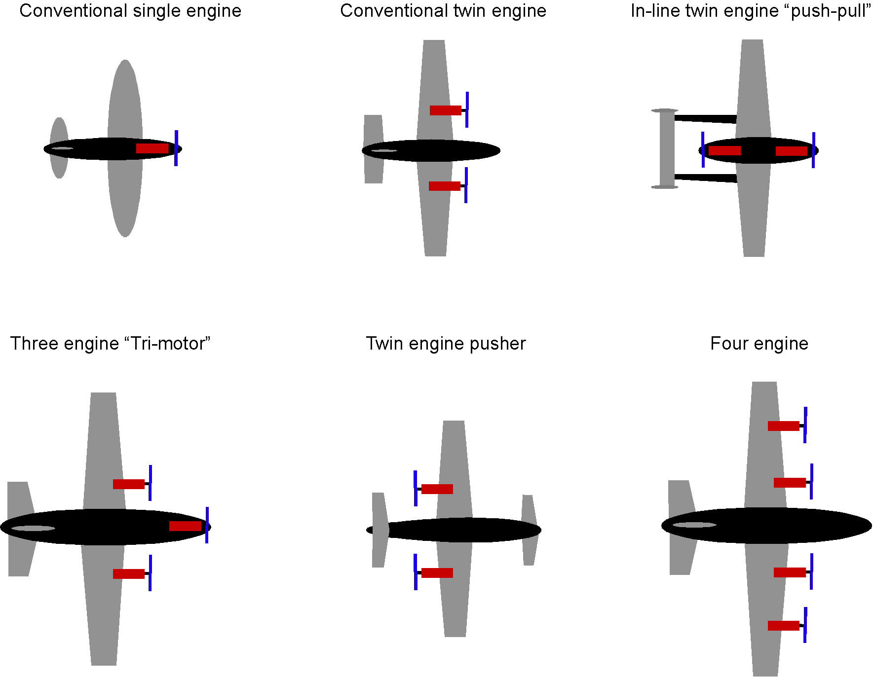
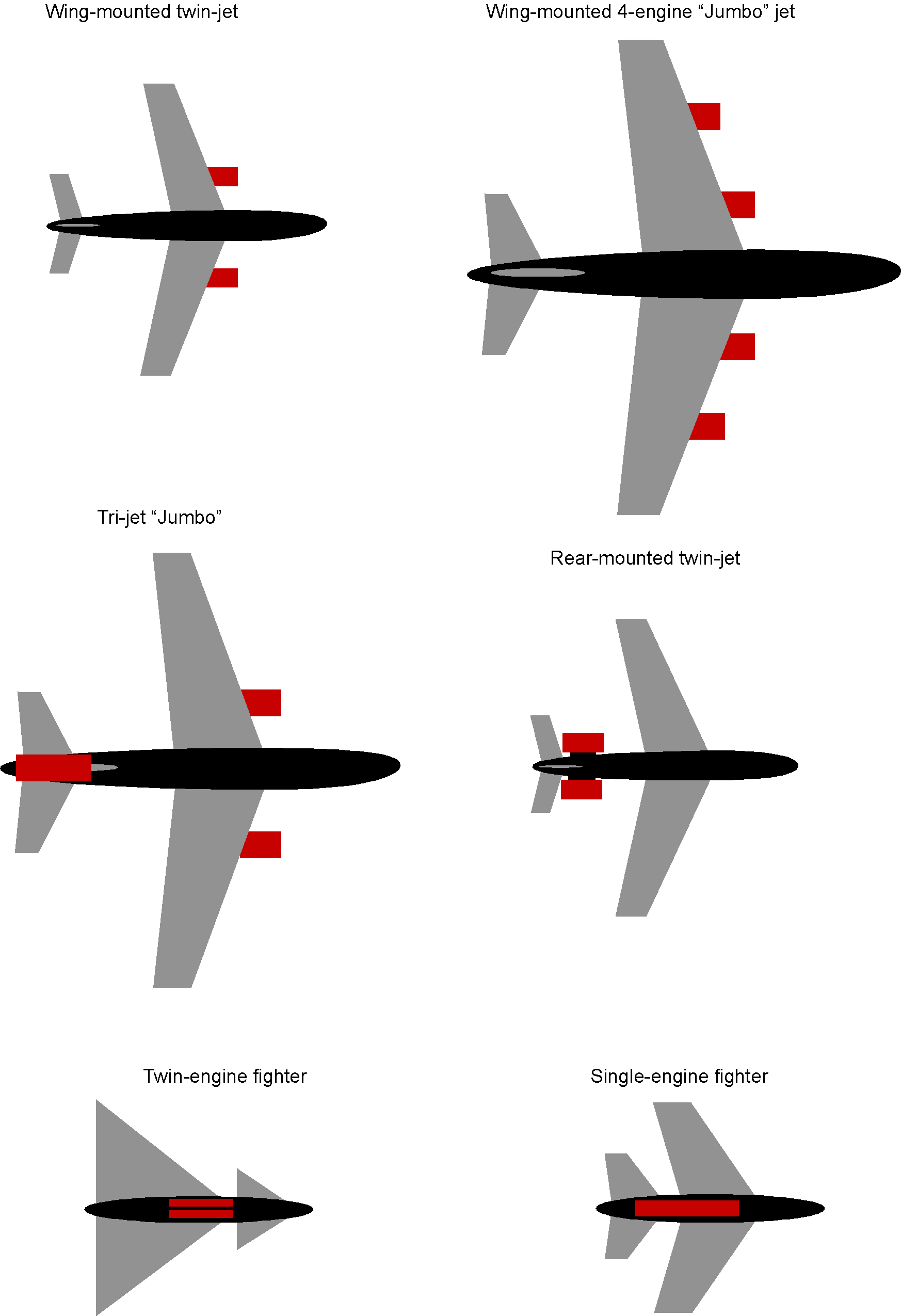
There are also various engine placements for jet airplanes, as illustrated in the figure below. Wing-mounted underslung engines are the most common configuration for airliners, although rear-mounted engines are standard for smaller regional and business jets. Military fighter aircraft generally have engines installed inside the fuselage, which reduces drag and improves ballistic tolerance.
Undercarriage Designs
The undercarriage, also known as the landing gear, supports the airplane’s weight while on the ground and absorbs the landing loads. However, the landing gear is also subjected to high forces during landing, including vertical and sideward loads. Therefore, the landing gear assembly must be as light as possible while still providing the necessary strength. To this end, the landing gear must be made from materials such as steel, aluminum castings, or, in some cases, titanium. Titanium is lightweight and robust, but it is more costly than steel and aluminum.
Numerous undercarriage or landing gear designs exist. The most common is the tricycle gear, which features two main gear leg assemblies, or “bogies,” and a single steerable nose wheel. This design gives the airplane good directional stability on the ground. Larger airplanes may use two or more wheels on each landing gear leg, and the very largest airplanes, such as the Boeing 747 and A380, may use three or four main gear legs.
Another typical design is the tailwheel undercarriage, also known as a “tail-dragger.” Tailwheel airplanes were used in the early days of aviation, so the tailwheel design has become known as conventional landing gear. In this design, the two main forward wheels will carry most of the airplane’s weight, and a smaller wheel is located at the tail. The conventional landing gear offers reduced weight, but this design is much less directionally stable on the ground. Also, the pilot may have difficulty seeing ahead while taxiing. Nevertheless, the tailwheel undercarriage is relatively common, especially on smaller airplanes, because it is lightweight and straightforward. However, such a configuration would be unsuitable for larger commercial airliners.
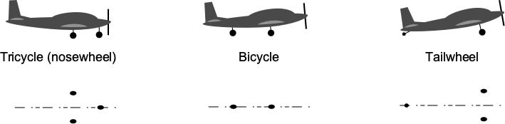
The tricycle gear is the most prevalent landing gear configuration used in aviation. In addition to the main wheels, to mitigate the potentially high impact of landing, most landing gear systems have a means of either absorbing or accepting shocks, thereby distributing the loads so that the structure is not damaged. This is typically done with an oleo strut that contains both air and oil. The air in the strut is compressed under load, giving progressive stiffness, and the oil provides the damping. Wheels and tires are designed specifically for aviation use, with characteristics that include the ability to absorb high-impact loads and some side loads.
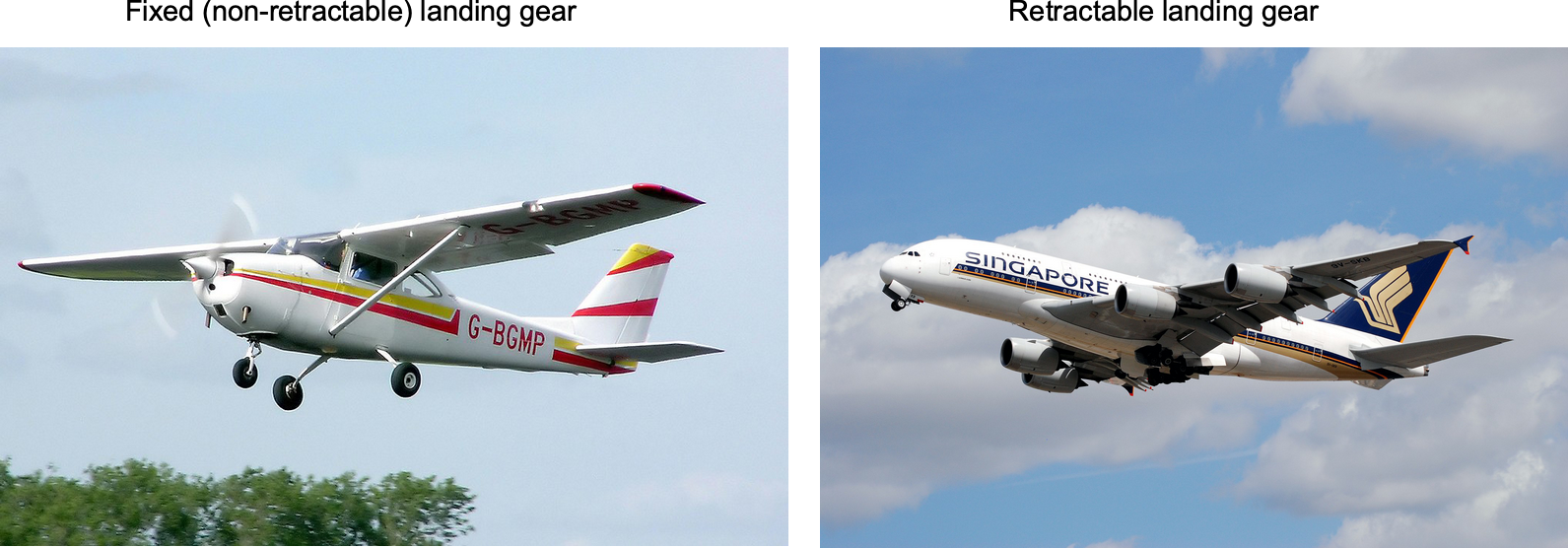
Smaller airplanes generally have fixed landing gear that does not retract. This approach features a simple, low-weight design but has higher aerodynamic drag. Sometimes, spats are used to cover and streamline the wheels. Larger and faster airplanes will inevitably have retractable landing gear, which is retracted into the fuselage and the wings after takeoff. While the retractable gear design significantly reduces drag, it also incurs a weight penalty and increased cost and maintenance requirements. Typically, a hydraulic system is used to raise and lower the landing gear.
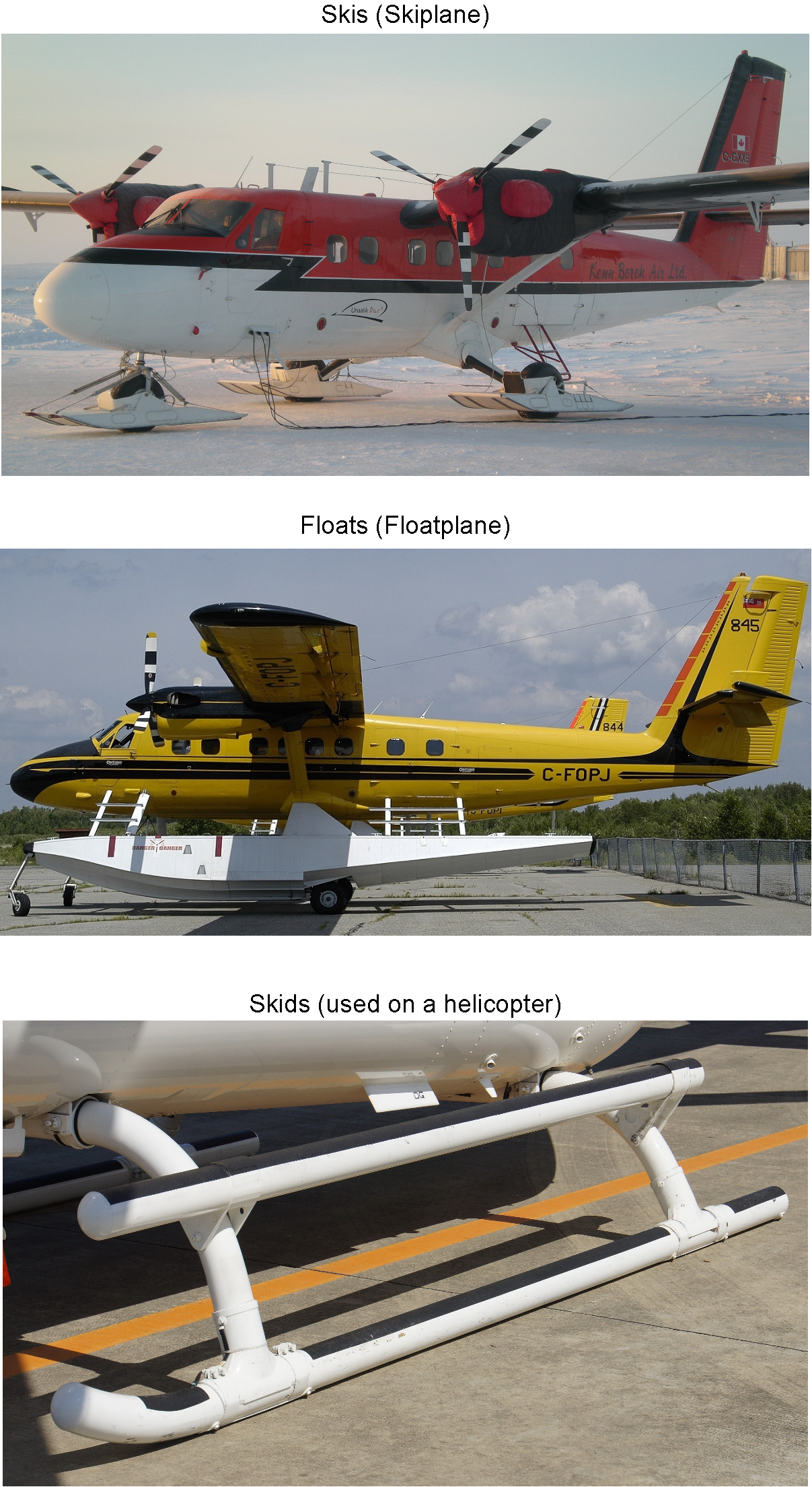
Not all aircraft have landing gear configured with wheels. Seaplanes are equipped with pontoons or floats, enabling them to operate on water. A large amount of drag (shear force) is produced on this type of gear during water operations, but an aircraft operating from water can be very useful. Additional engineering requirements are imposed on seaplanes to ensure that the flotation components are not only airworthy but also seaworthy. In this regard, further tests on the water and air are needed to ensure the airplane is safe and exhibits acceptable handling qualities throughout its operational envelope. Skis are used on some aircraft for flight operations in areas with snow and ice, enhancing capabilities in parts of the world where cold weather prevails for much of the year. Skids are a standard landing gear configuration for helicopters, providing a lightweight, stable, and robust platform for flight operations. They are also designed to absorb the impact forces during landings. Depending on their intended use and operational environment, some helicopters use other landing gear configurations, such as wheels or floats.
Anatomy of a Helicopter
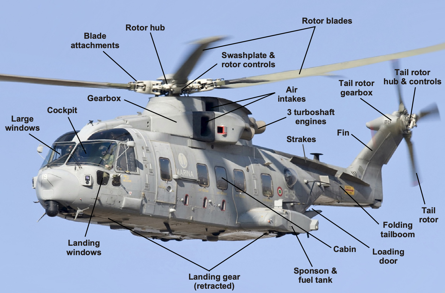
A helicopter, an example of which is shown in the figure below, is a form of rotorcraft. An essential advantage of the helicopter is that it can take off vertically from land or sea, hover motionless over a point, and fly in almost any direction. The main rotor provides the thrust to overcome the helicopter’s weight; changing the pitch of the blades together modulates the rotor thrust. The main rotor also provides control and forward propulsion by cyclically adjusting the blade angle and tilting the rotor disk’s plane of rotation. This approach alters the line of action of the rotor thrust vector, which provides aerodynamic forces and moments on the rotorcraft. The tail rotor provides side force and a moment to compensate for the torque reaction when driving the main rotor through a vertical shaft. Furthermore, by modulating the thrust of the tail rotor, which is done by changing the pitch of the blades through the pilot’s control inputs, directional (yaw) control is achieved.
However, despite the helicopter’s many advantages, it is a relatively low-speed aircraft with a maximum cruise airspeed of only 160 knots. It is also unable to fly very far, with a flight range of less than 500 miles, depending on the payload. The limitations of conventional helicopters have prompted the development of hybrid concepts, such as the tiltrotor, e.g., the V-22 Osprey, which combines some of the advantages of helicopters (i.e., vertical takeoff and landing capability) with those of airplanes (i.e., the ability to fly faster and further).
Anatomy of a Tiltrotor
A tiltrotor aircraft combines the vertical takeoff and landing capabilities of a helicopter with the speed and range of a fixed-wing airplane. The key feature of a tiltrotor is its large rotors mounted on nacelles at the tips of the wings, which can tilt from vertical to horizontal. During vertical takeoff and landing, the rotors act like helicopter blades, providing lift. Once airborne, the nacelles tilt forward, transforming the aircraft into an airplane for high-speed horizontal flight. This hybrid design enables tiltrotors to operate in diverse environments, ranging from confined spaces to long-distance travel.
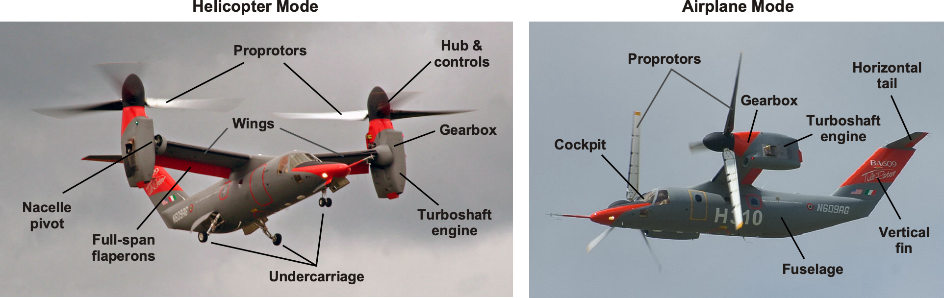
The anatomy of a tiltrotor includes tilting rotor systems, fixed wings with trailing-edge control surfaces (ailerons and flaps, or flaperons), turboshaft engines housed in nacelles, a central fuselage with a cockpit and passenger or cargo areas, and a tail section featuring vertical and horizontal stabilizers. The transition mechanism between helicopter and airplane modes is a critical component, enabling smooth conversions in flight dynamics. Tiltrotor aircraft, such as the V-22 Osprey and Leonardo AW-609, offer versatility for military and potential civilian applications, combining the benefits of helicopters and airplanes in a single platform.
Anatomy of an Airship
An airship is a type of aircraft that uses buoyancy to stay aloft. It is characterized by its large, helium-filled envelope and can be steered and controlled. It is essential to note that airship designs can vary significantly, encompassing rigid airships with an internal structure known as dirigibles or non-rigid airships, commonly referred to as blimps. An example of a blimp is shown in the schematic below.
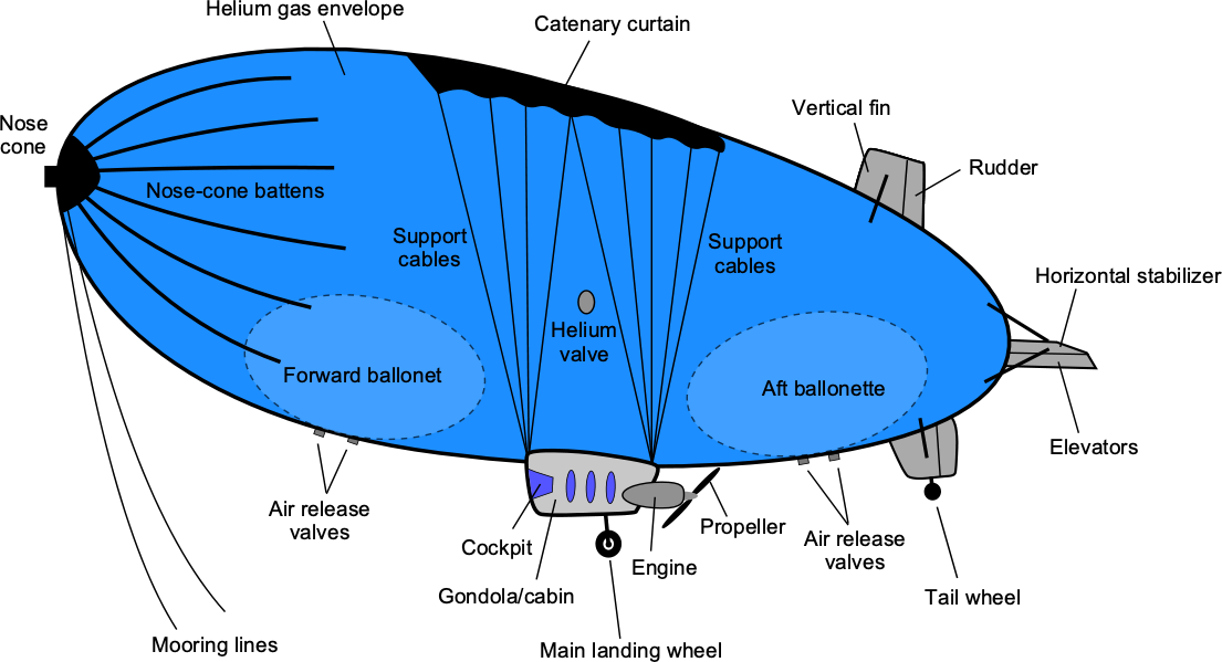
The envelope is the outermost part of the airship and is typically a large gasbag filled with helium, which provides the buoyancy needed to keep the airship aloft. The envelope is generally made of lightweight, non-porous, and highly durable materials, such as nylon or polyester. Below the gas envelope, the gondola hangs, accommodating the crew and passengers. The gondola also contains the cockpit, control systems, propulsion mechanisms, and navigation equipment. Airships are typically powered by one or more engines attached to the gondola or mounted externally. These engines drive propellers or fans to provide forward thrust, propelling the airship through the air.
The ballonets are internal air ballast tanks within the gas envelope. They help regulate the airship’s buoyancy by controlling the relative weight of air to helium, as air is approximately eight times as heavy as helium. By pumping air into or out of the ballonets, the pilot can control the altitude and pitch attitude of the airship. Airships also have aerodynamic control surfaces that enable them to maneuver and maintain stability during flight, functioning similarly to those of an airplane. The vertical and horizontal tails give the airship directional stability. The rudder controls yaw, and the elevator helps control pitch attitude, although the differential ballast in the ballonets gives primary pitch control for takeoff and landing.
Anatomy of Spacecraft
It is much more difficult to define or classify a rocket or spacecraft in the manner used for an airplane, because there are no officially designated categories or classes of spacecraft. The size, shape, and arrangement of a spacecraft’s components are highly mission-specific, leading to the development of various types of spacecraft over the years.
The name “spacecraft” refers to launch vehicles, satellites, or any other object intended to leave Earth’s atmosphere. Some launchers are reconfigurable, meaning they can be built with different stages or optional solid rocket boosters, depending on the mission and payload. For example, a payload launch to a high Earth orbit may require a different booster stage than one that goes into low orbit. However, spacecraft have one thing in common: they are all designed to operate at and beyond the limits of Earth’s atmosphere, and thus must be powered by rocket engines or, at the very least, have used them to reach space.
A multi-stage launcher houses a satellite or other payload in a fairing at the top of the launch vehicle. The stages consist of two or three rocket-powered launchers stacked on top of each other; these components are collectively referred to as the launch vehicle. Below is a schematic of the three-stage Saturn V launch vehicle.
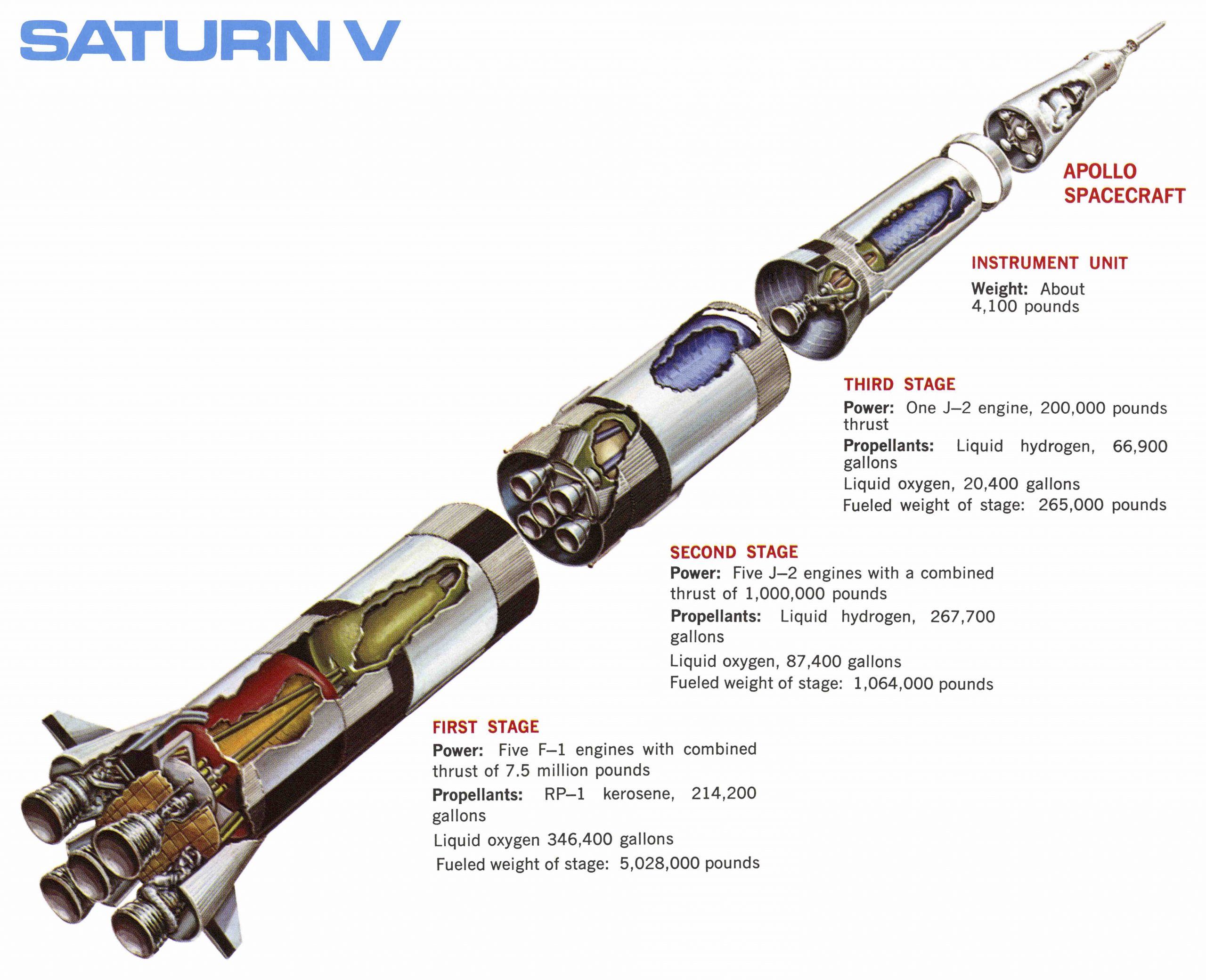
The first stage is used for the initial part of the launch until its fuel is exhausted, at which point it is jettisoned. The second stage then takes over, propelling the vehicle to a much higher altitude, and it is also jettisoned after its fuel is exhausted. Next, the third stage takes over and rapidly accelerates the payload to its orbital velocity. Finally, the third stage may be jettisoned as the payload reaches its required orbital altitude.
The advantage of launching a satellite with a multi-stage rocket is that it achieves a higher final velocity, as the rocket’s mass (weight) is substantially reduced after each stage is depleted of fuel and jettisoned, thereby requiring less total propellant. The ultimate engineering goal of staging is to maximize the payload ratio, meaning the largest amount of payload is carried up to the required burnout velocity using the least non-payload weight (i.e., the empty weight of the rocket structure plus its propellant). Two-stage rockets may launch payloads into low Earth orbit. However, three stages may be required for payloads that must reach higher altitudes or deep space. Multi-stage boosters are always needed to reach geostationary or geosynchronous orbits.
Very high propellant flow rates are required through a rocket engine to generate the necessary thrust at the nozzle exit. Upstream combustion chambers drive turbopumps to supply and regulate the required flow rates of fuel and oxidizer. The fuel is circulated in chambers around the nozzle to keep it cool and preheat it, a process known as regenerative cooling. Preheating the fuel also increases the final combustion efficiency and the rocket’s net thrust.
Another advantage of staging a launch booster is that each stage can use a different type of rocket engine tuned for its particular operating conditions. For example, the first-stage engines are optimized for use in the atmosphere. In contrast, the last stage can utilize engines more suited to space conditions, i.e., for operations in a vacuum. Furthermore, different fuels may be used for the various rocket engines.
A significant disadvantage of multi-stage launch vehicles is that the stages and their engines are lost when they burn up from kinetic heating during re-entry into Earth’s atmosphere. However, reusable launch vehicles are becoming more feasible, and the initial stage (or stages) are candidates for recovery, refurbishment, and reuse. Solid rocket boosters are often lost, but if jettisoned at lower altitudes, they can be recovered using parachutes and refurbished.
Solid rocket boosters can increase payload capability or augment launch speeds to reach higher orbital velocities and altitudes. This approach enables a primary launch vehicle to have greater flexibility in configuring it for a specific mission. While attaching a cluster of solid rocket boosters is sometimes considered inelegant, it is convenient (for reconfigurability) and relatively low-cost.
The commercial launch company SpaceX has been routinely recovering the first stage of its Falcon rocket, which is then steered back to(or to an offshore barge) for a vertical landing at the launch pad. Over the past few years, SpaceX has successfully recovered many of its Falcon 9 rockets.
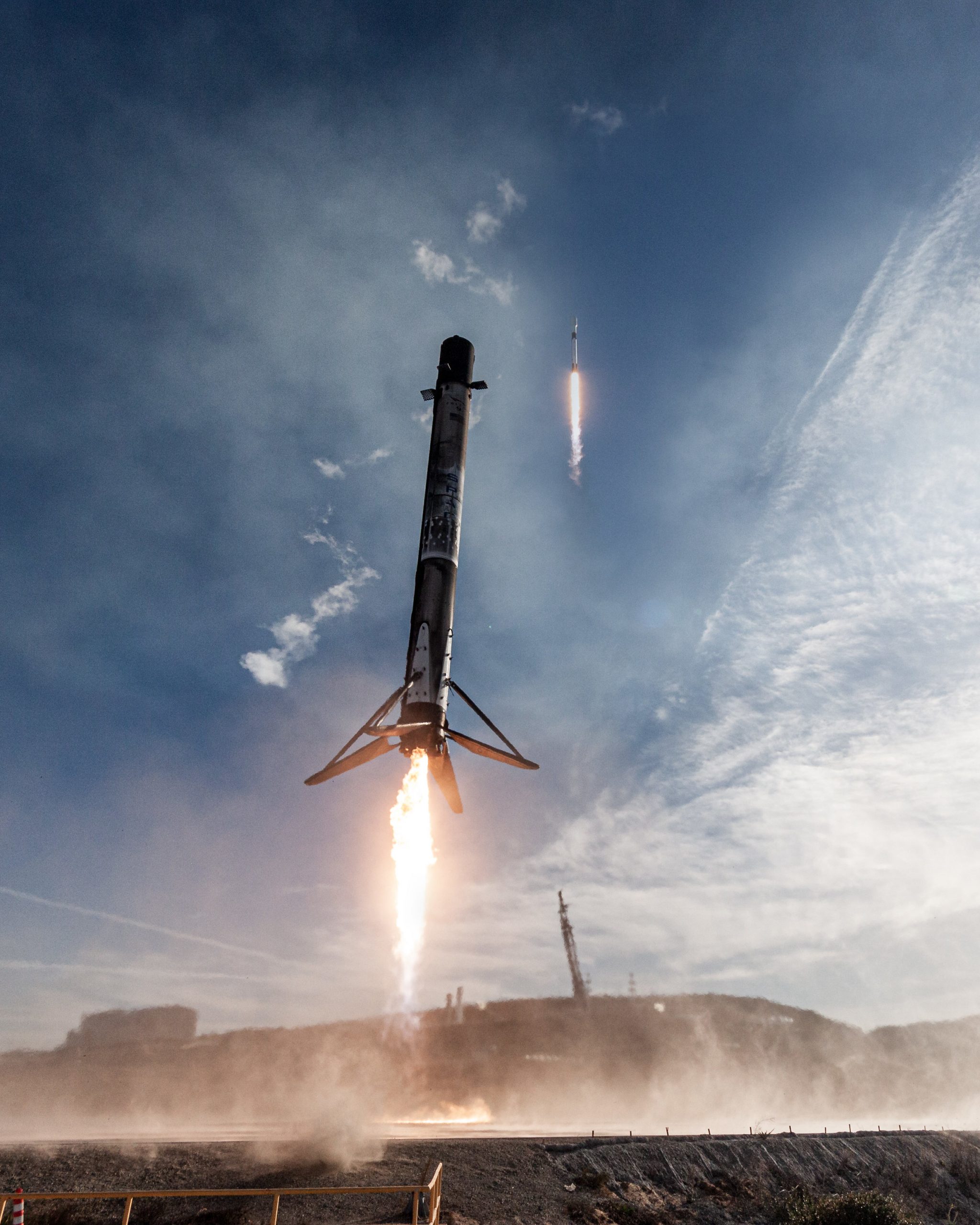
However, to accomplish this impressive feat, the first stage must carry more fuel than needed to launch the payload. Aerodynamic flight control surfaces and cold-jet attitude thrusters must also be added to the first stage to help steer it along the required trajectory to the landing point. Finally, retrobraking is performed by reigniting one or more of the main rocket engines. Achieving this incredible feat of flight dynamics and control presents unique challenges.
The ability to reuse rockets, such as the first-stage booster and its engines, is critical to making space launches more affordable. Launch vehicles can cost hundreds of millions of dollars, and reusing a first-stage booster, for example, can reduce a customer’s launch cost by tens of millions of dollars. Now retired from service, the Space Shuttle concept was the best example of a mostly reusable spacecraft. The heart of the concept, the Orbiter, was partly a spacecraft and partly an aircraft designed to re-enter the atmosphere after the mission and glide to a landing on a runway, albeit a very long one.
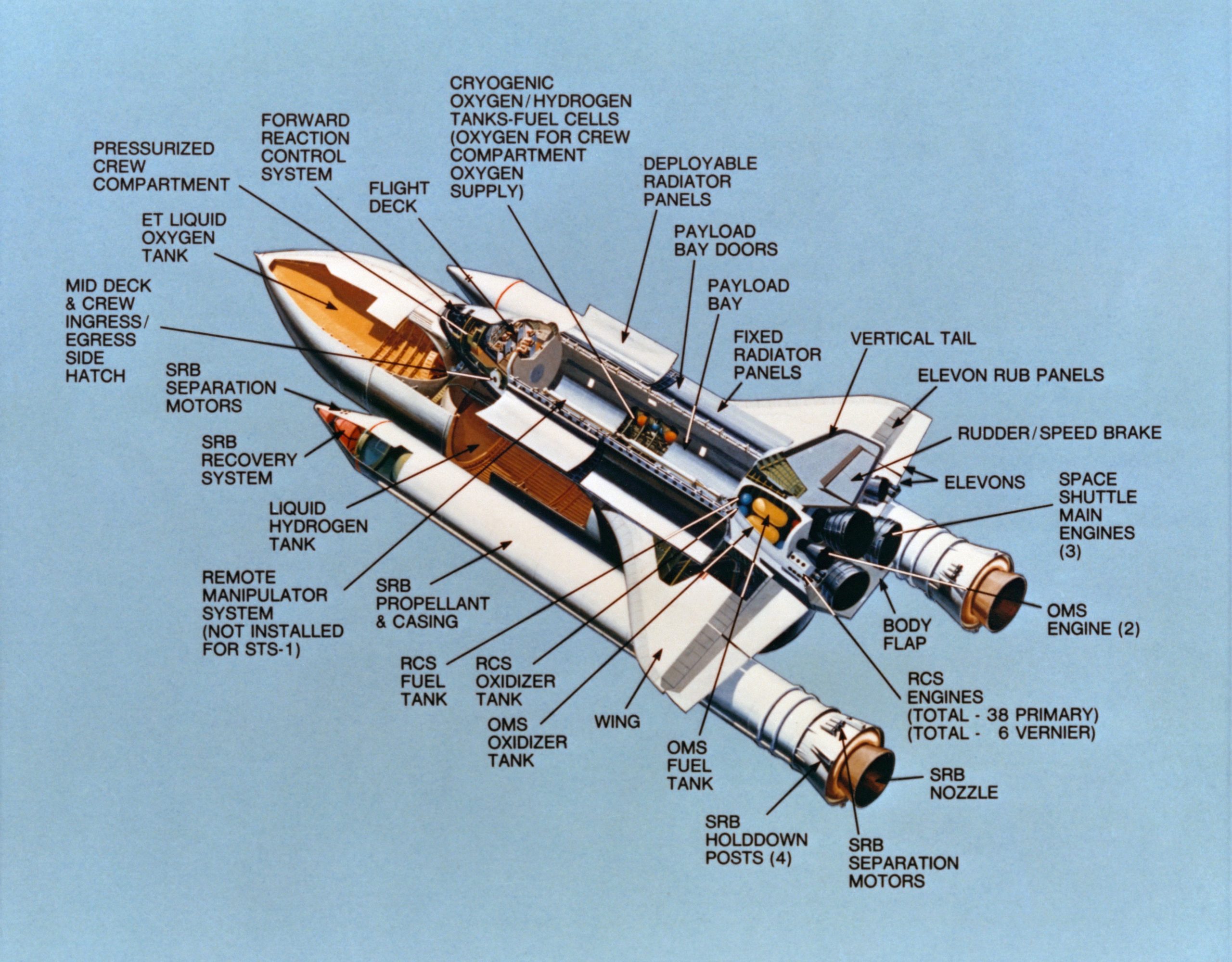
The Orbiter was powered by three extremely powerful rocket engines, which were only used during launch. The propellants for these rockets, liquid hydrogen (LH2) and liquid oxygen (LOX), were stored in the large external tank, which was jettisoned as the vehicle reached orbit and then burned up in the atmosphere. The two solid rocket boosters, or SRBs, burned for just 2 minutes during launch, and when their fuel was exhausted, they were jettisoned and parachuted into the ocean. The mission’s payload was entirely contained within the Orbiter, allowing it to be deployed into space. Other items could also be captured and returned to Earth, a handy feature when servicing the space station.
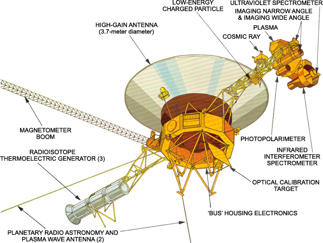
The payloads launched by rockets may comprise satellites, deep-space probes, interplanetary probes, telescopes, provisions for a space station, crewed capsules, or almost anything else. For example, the image below shows details of the Voyager deep-space probe, which features several different instruments and communication antennas. Satellites and spacecraft also have solar panels to provide the electrical power needed for their systems. Remember that there is no air in space, so aerodynamics is not a consideration, and the spacecraft can be almost any shape. Nevertheless, its mass distribution remains crucial because the spacecraft’s inertial characteristics along all three axes are essential for guidance and control.
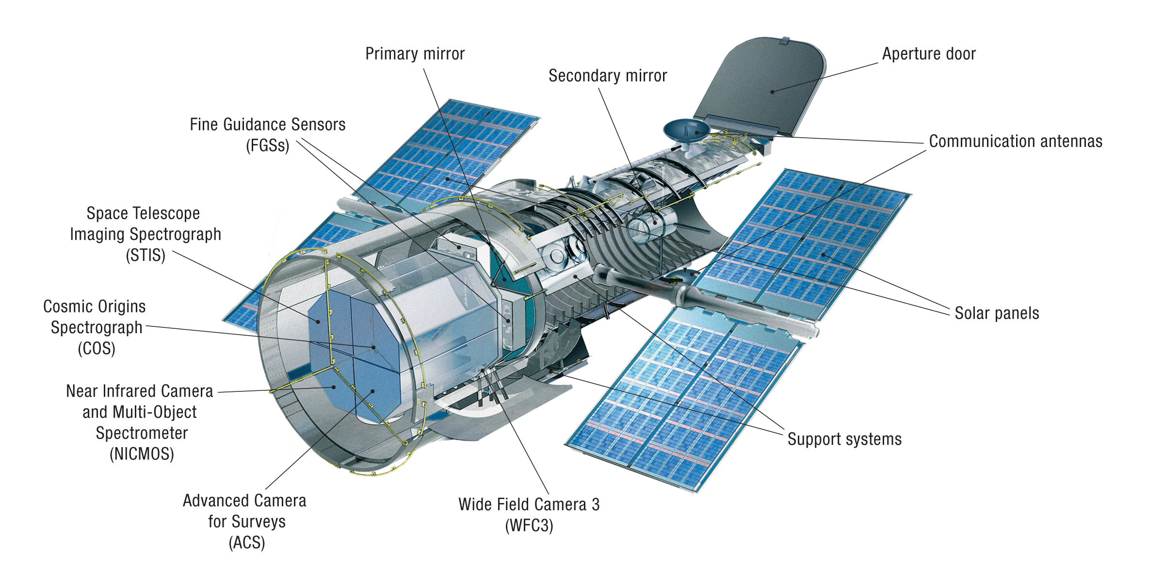
Since the Space Shuttle launched the Hubble Space Telescope (HST) into low Earth orbit, astronomers have gained a much more detailed understanding of our solar system and beyond. The figure below shows a cutaway of the HST. The forward part houses the main optical assembly, the center part houses the control electronics, and the aft part houses all instruments and sensor electronics. The solar panels provide the needed power.
Summary & Closure
Aircraft and spacecraft are each uniquely designed to perform specific functions and meet certain operational requirements. In this regard, aircraft and spacecraft will have different anatomies tailored to their respective missions. Airplanes have a fuselage that houses the cockpit and space for the payload (passengers and cargo), wings for generating lift, an empennage for stability and control, engines for propulsion, and landing gear for takeoff and landing. In contrast, spacecraft are characterized by specific design anatomy to fulfill a specialized mission. This anatomy may have a service module containing propulsion and power systems, a command module housing computers and communication equipment, solar panels for power generation, and thermal protection systems. All types of flight vehicles are intricately designed with considerations for aerodynamics, structural integrity, and mission requirements. However, aircraft are optimized for atmospheric flight, while spacecraft are tailored for operation in the vacuum of space.
5-Question Self-Assessment Quickquiz
For Further Thought or Discussion
- Research unusual types of airplanes that may not conform to the “normal” airplane configurations discussed in this chapter.
- It has been proposed that future airliners may not have passenger windows. Why? Discuss.
- Why do birds not have vertical tails?
- Research the purpose of using “stagger” on a biplane configuration.
- Could you discuss the relative advantages and disadvantages of a flying wing compared to a conventional airplane configuration?
- Discuss the potential relative engineering risks associated with a reusable rocket booster stage.
- Why is a helicopter a “low-speed” aircraft? Conduct research to identify factors that may limit a helicopter’s forward speed.
- What might be the relative advantages of a tiltrotor aircraft compared to a helicopter and an airplane?
Other Useful Online Resources
To learn more about the anatomy of aircraft and spacecraft, try some of these online resources:
- Airplane parts and functions tutorial by NASA – see here.
- For more information about aircraft anatomy, including differences between early and modern airplanes, explore the National Air & Space Museum website here.
- Video on building an Airbus A-350.
- Great graphics showing the internal structure of a jet airliner.
- This great video shows the ailerons, flaps, and spoilers on a Boeing 777.
- Video of the landing gear operation on a Boeing 767.
- Take a tour of the Rolls-Royce jet engine factory.
- Test your understanding of the parts of a rocket here.
- Have you ever wondered how to start a rocket engine?
- Aircraft Anatomy Quizlet.
- The worst-looking rockets ever designed!
- Why does a rocket launch require millions of gallons of water?
- See here for some great details about the anatomy of the Orion crew module.
- A look at how SpaceX achieves astonishing landing accuracy with the Falcon 9 rocket.
