42 Piston Engines
Introduction
The earliest practical piston engines were developed in the late 19th century. They were based on the Otto cycle, featuring a stationary crankshaft with pistons moving in cylinders arranged in a straight line (inline) or a “V” configuration. Louis Blériot’s Bleriot XI, which famously crossed the English Channel in 1909, used a 25-horsepower Anzani inline engine. More powerful rotary engines emerged later, primarily in the early 20th century, especially for aviation. In a rotary engine, the entire engine, including the cylinders, rotates around a fixed crankshaft. This design was popular in early aircraft engines because of its high power-to-weight ratio and compactness, making it suitable for the lightweight requirements of early aircraft.
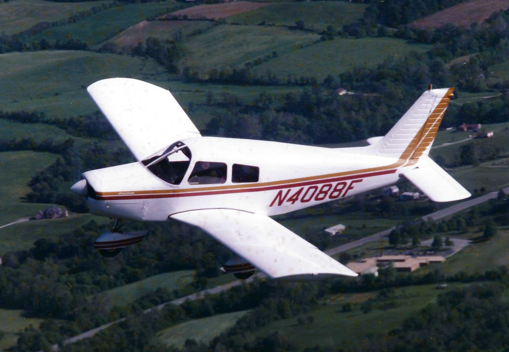
The rotary and radial types, once the workhorses of aviation, have given way to horizontally opposed “boxer” engines. These reciprocating piston internal combustion engines, which drive propellers, remain the powerhouses of modern general aviation. Their use in relatively low- to moderate-performance aircraft is a testament to their low cost, decent performance, and reliability. An example of a Piper Cherokee airplane is shown in the photograph below, which has a Lycoming 4-cylinder O-320, 160 hp (119.3 kW), horizontally opposed “boxer” piston engine driving a Sensenich fixed-pitch propeller. The advantages of this propulsion system are that it is reliable, affordable, and provides reasonable propulsive efficiency. However, the system is not readily scalable because the power-to-weight ratio of a piston engine decreases rapidly with increasing power output, making it unattractive for larger, heavier aircraft. In such cases, a turboprop engine will be preferred if a propeller is to be used.
Piston engines, including those with higher efficiency, such as diesel engines, may also be suitable for certain classes of drones and UAVs. These are particularly useful when the required flight range and/or endurance cannot be achieved using batteries alone, for example, by utilizing hybrid propulsion systems. One of the most common systems combines a gasoline (petrol) or diesel engine with electric motors, allowing operation solely on diesel or electrical power, or using both when needed. To this end, engineers must understand the basic principles of aircraft piston engine operation, including the effects of density altitude on power output and specific fuel consumption, as well as the associated propeller performance under flight conditions.
Learning Objectives
- Understand the basic principles of operation of a reciprocating piston engine, mainly as it is used for aviation applications.
- Appreciate the factors that affect the shaft power that can be developed from such an engine, and know how to read an aircraft piston engine performance chart.
Piston Engine Types
The first common type of piston engine used for aircraft was a rotary engine, which saw extensive use up through the 1920s. In this type of arrangement, the cylinders are arranged in a radial configuration that radiates outward from a central crankshaft, similar to the spokes of a wheel, as shown in the figure below. It also resembles a star when viewed from the front, so the type is sometimes referred to as a star engine. In a rotary engine, the entire crankcase and its attached cylinders rotate as a unit around the crankshaft, along with the propeller. The pistons are connected to the crankshaft using a primary rod assembly, and the remaining pistons and their connecting rods are attached to rings around the primary rod. The air and fuel inlets are connected to a carburation system, and the exhaust outlets are connected to a radial manifold. The inlet and outlet valves are opened and closed using a cam. In some versions, a carburetor delivers the fuel-air mix into the crankcase, allowing it to reach the cylinders through transfer ports, thereby eliminating the need for exhaust valves.
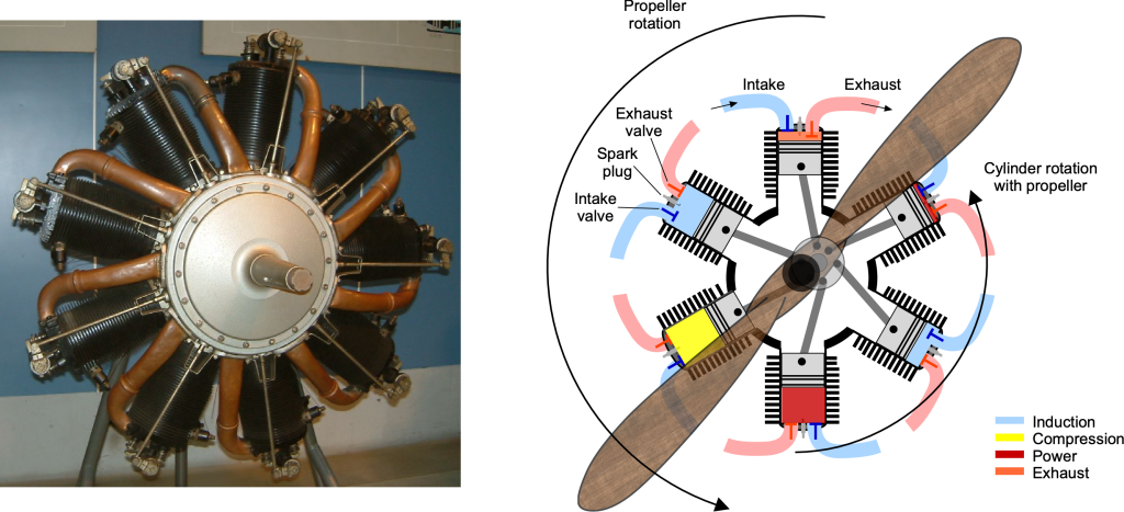
One advantage of the rotary engine design is its good cooling capability, as the cylinders rotate. However, a significant disadvantage is the large gyroscopic moments caused by the rotating engine mass. This characteristic led to several serious issues with the flight-handling qualities of early aircraft, specifically the inability to turn equally in both directions.
The radial engine is another early reciprocating piston engine used to power many pre-1950 airplanes, as shown in the photograph below. The radial engine has fixed (non-rotating) cylinders, and the propeller is connected to the crankshaft. The inlets are connected to a carburation system, and the exhaust outlets are connected to a system of pipes. In the radial engine, the gyroscopic effects on the airplane are much lower than for the rotary style of the engine, in which the cylinders rotate with the propeller. Consequently, radial engines were much preferred over the rotary type, which became obsolete for aircraft use after WWI.
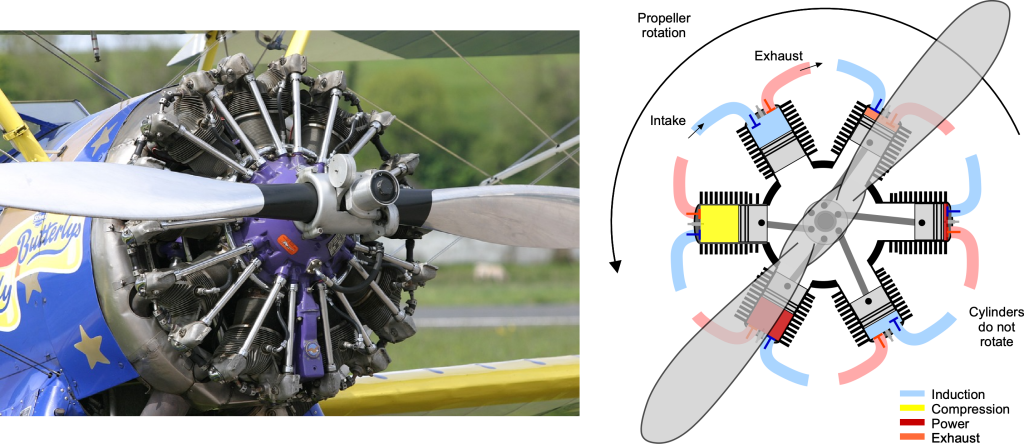
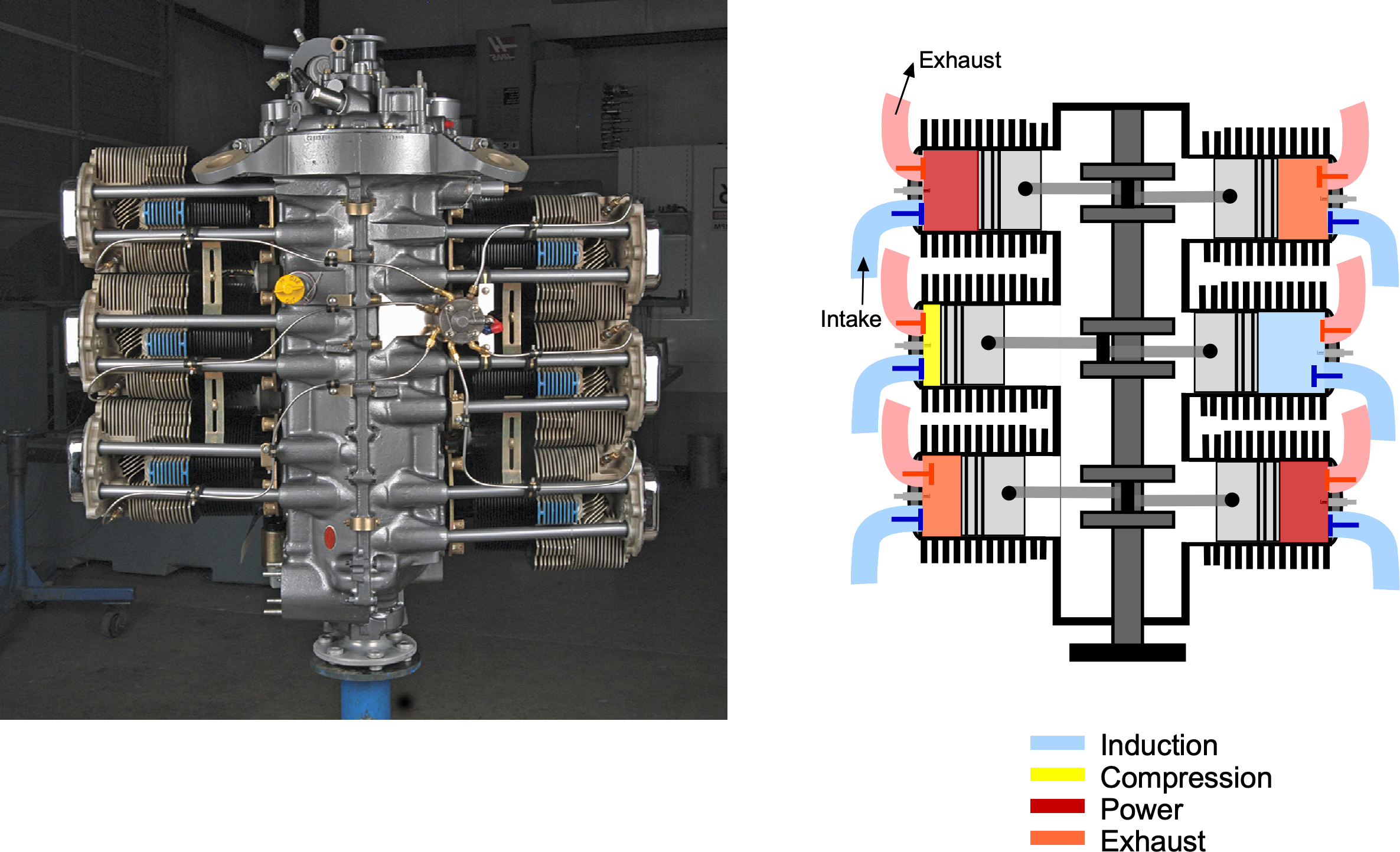
Powerful radial engines with 12 or more cylinders have been built for aviation use, primarily for airplanes constructed through the 1950s, increasing power output levels from approximately 2,000 hp (1,491 kW) to around 4,000 hp (2,983 kW). In addition, extra rows of radial cylinders can be added to increase the engine’s power. However, this approach rapidly increases the engine’s weight and also presents cooling challenges for the downstream rows of cylinders. The most powerful piston aircraft engine ever built was the Lycoming XR-7755, which had 36 cylinders and a shaft power output of 5,000 hp (3,700 kW). However, with the advent of jet engines, which offered better performance and efficiency, the XR-7755 project was eventually discontinued, and this engine never powered an aircraft.
Modern piston aero-engines for aircraft are usually flat and horizontally opposed, as shown in the figure below. The horizontally opposed engine configuration is also known as a “boxer” or “flat” engine. In this design, the cylinders are arranged in two banks on opposite sides of the crankshaft, creating a flat, wide configuration that yields a more streamlined, aerodynamic profile. This is important for minimizing drag and also allows for efficient air cooling. Several manufacturers, including Lycoming, Teledyne Continental, and Rotax, produce piston engines suitable for use in aircraft. They are manufactured with 4, 6, or 8 cylinders, with power ratings ranging from approximately 125 hp (93 kW) to 600 hp (441 kW). They also come in normally aspirated and supercharged (i.e., forced induction) forms, as well as carbureted and fuel-injected variants; fuel injection is typically used for higher-performance engines.
Superchargers and turbochargers are forced-induction systems used in aircraft engines to increase intake air pressure, enabling better combustion and improved engine performance. Supercharging or turbocharging (or both) can be used to increase the power of a piston engine and maintain its power output at higher flight altitudes. This is a suitable solution for higher-performance airplanes, despite the penalties of some extra engine weight and increased maintenance costs.
While modern piston aero-engines are mechanically reliable and robust, one concern is that they are relatively heavy compared to their power output. Their power-to-weight ratios are relatively low, only about 0.2 hp/lb (0.33 kW/kg) to 0.4 hp/lb (0.66 kW/kg). Therefore, when such engines are required to produce higher power levels, they can become prohibitively heavy for aircraft use. This reason is why a turboshaft engine is usually necessary to drive a propeller (i.e., a turboprop) after a specific power requirement for flight is reached. A turboprop has a significantly better power-to-weight ratio, ranging from about 0.8 hp/lb (1.32 kW/kg) to 1.2 hp/lb (1.97 kW/kg). While turboshaft engines have a higher capital and maintenance cost per power unit, their better specific fuel consumption and reliability make them very attractive for larger propeller-driven aircraft.
Check Your Understanding #1 – Quantifying a unit of horsepower
The output at the engine shaft is often measured in “horsepower,” denoted by the unit symbol “hp.” This unit is attributed to the Scottish engineer James Watt, who sought to compare the power output of his steam engines with that of horses to help market the engines more effectively. Watt conducted various experiments and determined that a typical farm horse could, on average, steadily lift a 600 lb weight over a pulley system for an average distance of 63.9 feet in approximately 69 seconds. Using this information, explain how James Watt came up with the result that one hp = 550 ft-lb s .
.
Show solution/hide solution.
The work done by the farm horse will be the force it pulls  the distance it pulls it, so with a weight
  of 600 lb hanging over a simple pulley, that is also the force applied. Therefore,
  and
and
![\[ \mbox{Work} = F \times d = W \times d= 600 \times 63.9 = 38,340~\mbox{ft-lb}\]](https://eaglepubs.erau.edu/app/uploads/quicklatex/quicklatex.com-d64ad96d620fe13398dd92b2fa392fab_l3.svg "Rendered by QuickLaTeX.com")
Power is the rate of doing work, so work per unit time, i.e.,
![\[ \mbox{Power} = \frac{\mbox{Work}}{\mbox{time}} = \frac{38,340}{69} = 555.65~\mbox{ft-lb s$^{-1}$} \]](https://eaglepubs.erau.edu/app/uploads/quicklatex/quicklatex.com-f2bf31b02fa694792be2b749e8c5abcf_l3.svg "Rendered by QuickLaTeX.com")
This latter value is roughly the power produced by a horse, and James Watt settled on one hp = 550 ft-lb s.
James Watt was not concerned about excessive accuracy. All he wanted was a simple but representative quantitative measure of the power delivered by a horse relative to what his steam engines could produce, so that he could market his engines more effectively. In addition, the term made sense to farmers and others who used horses to move equipment and other items. Therefore, for a 10 hp steam engine, the purchaser knew they were buying a machine equivalent to what ten horses could do. The unit of “horsepower” has since become established and is still used almost universally as a unit of power output today.
Principle of Operation
The principle of operation of a reciprocating internal spark-ignition combustion engine is based on the Otto cycle, as shown in the figure below. Named after Nikolaus Otto, who built the first successful four-stroke piston engine in 1876, the cycle represents the basis of modern gasoline-fueled engines. A cam synchronizes the piston’s up-and-down movement with the opening and closing of the two valves (intake and exhaust). This allows the sequential entry of the fuel and air mixture, followed by compression and combustion, and then the exit of the exhaust gases.
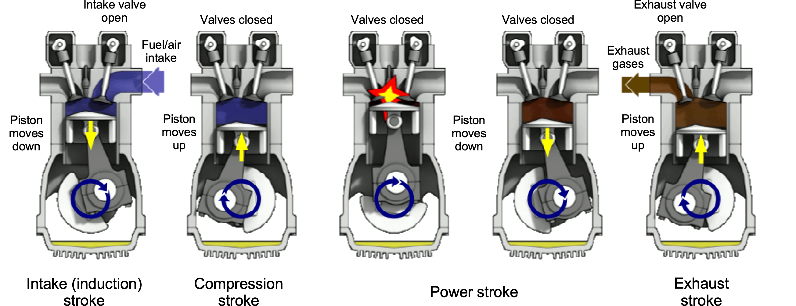
In summary, the operation of the engine consists of four cycles (or strokes), as shown in the animation below, namely:
- During the intake stroke, the piston moves downward in the cylinder, and the cam opens the intake valve. A carburetor or fuel injection system draws the air-fuel mixture into the cylinder.
- The compression stroke is the period during which the intake and exhaust valves are closed. The upward-moving piston then compresses the fuel/air mixture to the point that it will support combustion.
- The power stroke is where a spark plug ignites the compressed mixture. The resulting flame front and expanding gases (called deflagration) progressively force the piston downward in the cylinder, driving the crankshaft.
- The exhaust stroke is when the exhaust valve opens, and the upward-moving piston forces the combustion products out of the cylinder before the entire four-stroke process begins again.
A piston engine may also operate on the principle of the Diesel cycle, where the much higher compression in the cylinder raises the temperature sufficiently to cause the fuel to burn without the use of a spark plug. Another advantage of a diesel engine is its better thermal efficiency and lower specific fuel consumption. In many countries, diesel fuel, which is chemically similar to jet fuel (Jet-A), is also less expensive than gasoline. However, diesel engines are not used much in aviation applications.
Thermodynamics
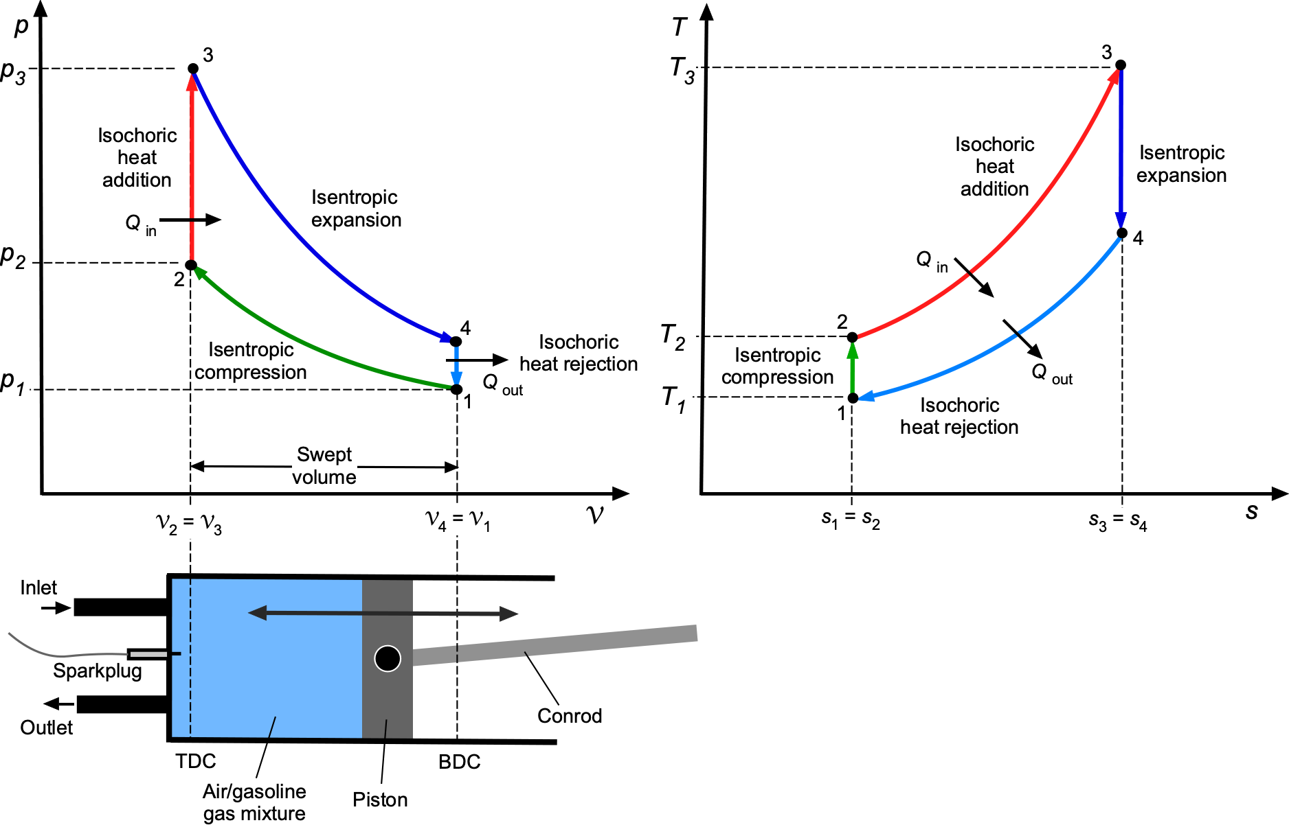
The Otto spark-ignition cycle consists of four internally reversible processes for a fixed mass of a fuel-air mixture, typically modeled as air, as an ideal gas. The cycle begins at state 1, with the piston at bottom dead center (BDC) and the cylinder filled with the air-fuel gas mixture. From state 1 to 2, the piston moves upward with both valves closed, producing an isentropic compression that reduces the volume from  to
to  and raises the pressure and temperature without heat exchange. The compression ratio,
  , is typically about 8.5:1 in naturally aspirated engines; supercharging increases
  and thereby the power output.
 and
and  diagrams of the Otto cycle.
From state 2 to 3, constant-volume heat addition occurs when the spark plug ignites the mixture. The temperature and pressure rise abruptly at fixed as heat  is added. From 3 to 4, an isentropic expansion takes place as the piston moves from TDC back to BDC. The gas does work on the piston, and the pressure and temperature decrease during this power stroke. From 4 to 1, a constant-volume heat rejection process occurs when the exhaust valve opens, releasing heat
  at fixed volume and completing the cycle.
On the diagram, the compression and expansion legs follow  , joined by vertical constant-volume lines for heat addition and rejection. The infinitesimal work done by the gas is
(1) 
so over one complete cycle, then
(2) 
This equals the signed area enclosed by the loop on the diagram, which is positive (counterclockwise) for power output from an engine. On the diagram, the two isentropic legs are vertical and the constant-volume processes follow  . The heat transfer is
(3) 
So the area enclosed represents the net heat exchange, which equals the net work according to the First Law of Thermodynamics. The heat interactions are
(4) 
giving the net work  . From the isentropic relations, then
(5) 
the thermal efficiency of the Otto cycle becomes
(6) 
Therefore, the efficiency depends only on the compression ratio and the specific heat ratio  . In practice, is limited by pre-ignition or knock, which is determined by the octane rating of the fuel.
Effects on Power
For a piston engine, the power from the engine  to the crankshaft (the so-called shaft brake power) can be expressed by
(7) 
where  is the total displacement or swept volume,
  is the mean effective pressure (pressure in the cylinders), and rpm is the crankshaft revolutions per minute.
The swept volume by the piston as it moves up and down inside the cylinder equals the displacement of one cylinder; therefore, the total engine displacement is that value multiplied by the number of cylinders, e.g., 5.9 liters (5,900 cc) or 360 cubic inches. For any reciprocating engine, the cylinder volume varies between the clearance volume at top dead center (TDC),  , and the maximum volume at bottom dead center (BDC),
  . The displacement (swept) volume is
(8) 
It is convenient to define the indicated mean effective pressure (IMEP) or as the equivalent constant pressure that, if applied during expansion over  , would yield the same net cycle work, i.e.,
(9) 
If the crankshaft rotates at  revolutions per minute and the engine has
  cylinders, the cycle frequency per cylinder is
  for a four-stroke and
  for a two-stroke engine, expressed in cycles per second. The power is then
(10) 
Therefore, the power output is directly proportional to the loop area on the diagram, the displacement volume, and the number of cycles per second.
Detailed dynamometer testing is typically conducted to accurately assess an engine’s performance, considering various parameters and conditions. Additionally, the specific configuration and characteristics of the engine, as well as any forced-induction systems (such as superchargers or turbochargers), can affect overall power output. The name “brake power” comes from the fact that the power is measured using a brake-type dynamometer, which provides resistance or braking torque at the engine shaft. Remember that a torque,  , is the product of a force times a distance, so it has units of work. Power is the rate of doing work, so the power, , at the shaft is the product of the torque and angular velocity of the shaft, i.e.,
  .
.
Power Limitations
It will be apparent from Eq. 7 that the power out from the engine can be increased by:
- Increasing the swept volume, i.e., by increasing the cylinder bore, stroke, number of cylinders, or all of these things.
- Increasing the pressure in the cylinder by the appropriate design of the combustion chamber and/or the piston shape, or by turbocharging the air entering the cylinders.
- Running the engine at higher values of rpm. However, the rpm will be limited in part by keeping the propeller’s tip Mach number below the speed of sound.
There is a practical limit to all of these factors, partly due to the mechanical stresses and temperatures in the engine that prevent failure. To a large extent, the design of a piston engine depends on selecting high-strength and high-temperature metals, along with appropriate metallurgy, to ensure the engine exhibits good operational reliability and durability, particularly for the exhaust valves. In aviation engines, which operate at high power settings and average temperatures, the exhaust valves are often filled with sodium, which enhances thermal conduction away from the valve stems and seats, thereby keeping the engine cooler. The maximum attainable rpm of the engine will also be limited by the propeller tip speed, which should be kept below the speed of sound (Mach 1) to maintain propulsive efficiency and reduce noise levels. Propellers with high tip speeds approaching the speed of sound are always very noisy.
Altitude Effects
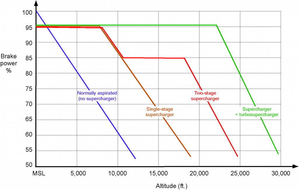
As the airplane’s flight altitude changes, the available engine power decreases, as shown in the figure below. Lower air density affects the amount of oxygen available for combustion in the engine cylinders. Because engine power output is directly related to the amount of oxygen available for combustion, a decrease in air density reduces engine performance. Engines also rely on the pressure difference between the outside air and the combustion chamber to facilitate the intake of air and the expulsion of exhaust gases. Reduced atmospheric pressure at higher altitudes can impact the efficiency of these processes, affecting engine performance. While lower temperatures can be beneficial for engine cooling, they also influence combustion efficiency. Cooler air can improve air-fuel mixture density, but it may also affect fuel vaporization, potentially affecting combustion efficiency. So, the power output decreases or lapses with increasing density altitude.
An approximation for the effects of density altitude on the power output of a normally aspirated (non-supercharged) piston engine is to assume that
(11) 
where  is the power available at altitude and
  is the power available at mean sea level conditions. Remember that the density ratio,
  , of the air, which is a surrogate measure of the oxygen content, can be calculated using the ISA model from measurements of pressure altitude and outside air temperature at that altitude. An empirical correction for a normally aspirated engine that is often used in practice is
(12) 
Supercharging
It can also be seen that supercharging can maintain a piston engine’s rated power at much higher altitudes. This outcome occurs because a supercharger increases the mean effective pressure and density of the air supplied to the engine intake, thereby boosting the manifold pressure and the oxygen content of the inducted air. The consequence is that more fuel can be burned, thereby increasing the power available from the engine at lower altitudes and maintaining that power at higher altitudes.
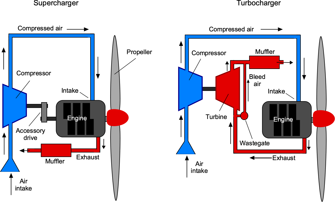
Superchargers and turbochargers have been used extensively to maintain the power output from aero-engines. Some of the earlier high-powered radial engines employed a combined system known as a “turbo-supercharger,” which combined a supercharger and a turbocharger to maximize performance across a broad range of altitudes. As shown in the figure below, the engine mechanically drives superchargers, typically through a belt connected to an accessory drive from the crankshaft. The engine’s exhaust gases drive the turbochargers, which consist of a turbine and a compressor connected by a shaft. The exhaust gas spins the turbine, which, in turn, rotates the compressor, forcing more air into the engine and, consequently, into the fuel management system. Turbochargers are generally more efficient than superchargers because they harness waste energy from the exhaust gases, rather than drawing mechanical power directly from the engine.
The mass flow rate of air into the engine is proportional to the air density and the engine displacement volume, so increasing intake density increases the available mass flow rate, i.e.,
(13) 
where  is the mass flow rate of air into the cylinders,
  is the ambient intake air density, and is the engine displacement volume per cycle.
Assuming a roughly constant air-fuel ratio, increasing permits a proportional increase in the fuel flow rate  , and hence, a proportional increase in power output. The ideal power increase from boosting can be estimated as
(14) 
where  is the new power output,
  is the rated power at sea level ambient conditions,
  is the boosted intake manifold pressure above the ambient atmospheric pressure,
  .
.
The efficiency of a turbocharger compared to a mechanically driven supercharger can be illustrated by considering that the mechanical load  imposed by a supercharger reduces the net power output, i.e.,
(15) 
whereas a turbocharger does not directly extract power from the crankshaft, relying instead on exhaust energy that would otherwise be wasted.
Compressing the intake air through supercharging or turbocharging not only increases its pressure but also raises its temperature. According to the ideal gas law, an increase in temperature at constant pressure reduces air density, partially offsetting the benefits of compression. The temperature rise through an ideal isentropic compression process is given by
(16) 
where  and
and  are the inlet and outlet temperatures across the intercooler,
  and
and  are the inlet and outlet pressures, and is the ratio of specific heats = 1.4 for air.
Intercoolers are used to mitigate the temperature rise and maximize the intake air density. An intercooler is a heat exchanger placed between stages of compression (in multi-stage supercharging) or between the compressor and the engine intake (in turbocharged systems). The intercooler cools the compressed air before it enters the engine cylinders, thereby increasing its density and improving the mass flow rate into the engine.
The benefit of intercooling can be quantified by considering the reduction in intake temperature, which results in a denser charge and a greater available oxygen mass per cycle. The net effect is improved engine power output, better fuel efficiency, and a reduced tendency for detonation (engine knock) at high manifold pressures. Aircraft engines that employed two-stage supercharging often incorporated intercoolers or aftercoolers between stages. In turbocharged systems, such as those used on high-altitude bombers during WWII, intercoolers were critical for maintaining engine performance and reliability at altitudes above 25,000 feet.
There may be a further boost in engine power as the flight speed  increases. The pressure of the air entering the engine will generally increase by an amount proportional to the dynamic pressure, i.e.,
  . Therefore, the power from the engine increases slightly because of a ram air effect. Ram air, a dynamic pressure effect, can be significant for some aircraft, especially those flying at airspeeds above 250 knots. However, pressure losses in the ducting between the air intake and the engine tend to reduce the significance of this potentially beneficial effect. Nowadays, reciprocating engines are used in lower-speed general aviation aircraft, so the ram air effect can usually be ignored for its impact on engine performance. From a design perspective, relying on ram air effects at any airspeed would be inadvisable when sizing an engine to an airframe.
Engine Performance Charts
Engine manufacturers provide detailed charts that enable engineers to calculate shaft power for any combination of altitude and temperature, as shown in the figure below. Notice that there are two sides to this chart: the left side represents the mean sea-level (MSL) power output performance, and the right side represents the performance at altitude.
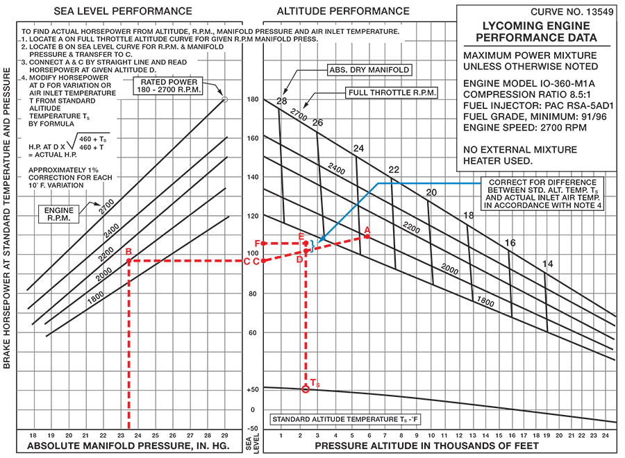
The instructions on the chart explain how it is used to determine the engine’s brake power. This chart differs from what pilots would use in flight, but engineers use it to estimate the available engine power under different flight conditions. The chart can be used to make all of the needed measurements to determine power output. Standard cockpit instruments can be used to measure pressure altitude, engine rpm, manifold pressure, and outside air temperature, which is very useful for flight testing.
The power available at the engine shaft (the brake horsepower or bhp) can be determined given measurements of the following:
- Pressure altitude can be measured directly on the altimeter by setting the reference pressure in the Kollsman window to the standard sea level pressure (MSL) conditions of 29.92 inches of mercury.
- Air temperature would be measured in flight using an appropriately calibrated outside air temperature (OAT) gauge.
- The engine rpm, which would be measured using a tachometer. While a tachometer is part of the standard cockpit instruments, an optical tachometer that counts the passage of the propeller blades is more accurate.
- Manifold pressure can be measured on the manifold pressure gauge, which is also part of the standard cockpit instruments.
The process begins by entering the left chart (MSL performance) at the bottom, using the manifold pressure measurement, and then reading up to point B on the lines of constant engine rpm. Notice that interpolation will generally be required. Reading across the axis to the right at point C provides the engine brake power at MSL standard conditions.
The next step in the process is to establish engine performance at altitude, which is done using the right-side chart. After carrying point C onto the left chart, a straight line is drawn between points C and A, with point A positioned at the corresponding point on the rpm and manifold pressure map. To find the available power at a given pressure altitude, it is necessary to move along the line AC. Reading to the left axis will give the brake power output at altitude under standard temperature conditions. Finally, a minor correction is made for non-standard temperatures (the formula is shown on the chart) to determine the final brake power output at point F. Notice again that interpolation will be required throughout this process.
Engine Designators
Aircraft piston engines usually have a designator, e.g., IO-360-A. The question is, what does this mean? However, decoding the designator is easy! The prefix “O” means horizontally opposed. The prefix “I” stands for fuel injection. The “360” is the swept volume of the pistons in cubic inches. The “A” is just a model of the engine, typically configured for a specific aircraft. An “AIO” prefix indicates that the engine is also qualified for aerobatics, as it features an oil system capable of withstanding inverted flight.
Brake Specific Fuel Consumption (BSFC)
The efficiency of a piston engine is measured by its power-specific or brake-specific fuel consumption (BSFC), often denoted by the symbol  . The BSFC measures the fuel used (in units of mass or weight) per unit of power supplied (in horsepower or kilowatts) per unit of time of engine operation (usually one hour). BSFC is used as a measure of the fuel efficiency of any engine that burns fuel and produces rotational or shaft power.
The BSFC is defined as
(17) 
The units of BSFC are typically in lb hp hr in the U.S. customary system, or kg kW hr or grams per kilowatt-hour (g/kWh) in the SI system. Notice that the unit of mass (kilogram or gram) is used in the SI units of BSFC, an anomaly of the SI system. However, the time unit is hours in both cases.
For a piston engine used on an aircraft, the values of BSFC are typically in the range of 0.4 to 0.6 lb hp hr (0.24 to 0.37 kg/kWh), as shown in the figure below. These values are approximate and may vary based on factors such as engine design, operating conditions (e.g., cruising, takeoff, climb), and the specific engine model. Additionally, advancements in engine technology may improve fuel efficiency compared to older engines.
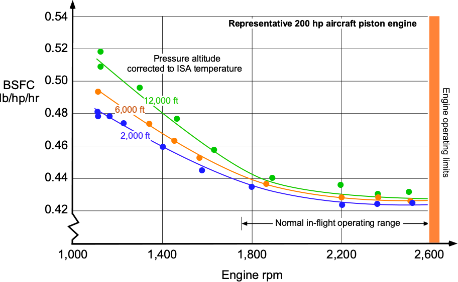
There is usually some dependence of BSFC on flight altitude, with the values increasing somewhat. Notice that the best (lowest) BSFC is obtained when the engine operates at or near its rated rpm and power output. Today, the best-performing and most efficient piston engines are supercharged diesel engines, which have better thermal efficiencies and BSFC values in the 0.45 to 0.7 lb hp hr range (0.27 to 0.43 kg/kWh).
Turbocharging generally improves brake-specific fuel consumption (BSFC) compared to a naturally aspirated engine, particularly at higher altitudes. Turbocharging increases the intake air pressure and density, allowing more complete combustion and improving the engine’s volumetric efficiency. Because turbochargers harness waste energy from the exhaust gases rather than imposing a mechanical load on the crankshaft, they boost engine power output without significantly increasing fuel consumption. As a result, the BSFC tends to decrease, meaning that less fuel is needed per unit of useful power output.
For example, consider a naturally aspirated piston engine producing 200 hp with a fuel mass flow rate of 60 lb/h. Its BSFC is
(18) 
Now, assume the same engine is equipped with a turbocharger, producing 270 hp at a slightly increased fuel mass flow rate of 75 lb/h. The turbocharged BSFC is
(19) 
Therefore, while the fuel consumption increased, the power output increased proportionally more, resulting in a lower BSFC. The engine becomes more fuel-efficient per unit of power after turbocharging.
While turbocharging improves BSFC and altitude performance, several tradeoffs must be considered. At very high boost pressures, intake air temperature increases significantly, potentially requiring fuel-air mixture enrichment to prevent engine knock, which can partially degrade the BSFC benefits. Additionally, turbochargers introduce thermal management challenges because of the high temperatures encountered in the exhaust turbine and the compressed intake air. Proper intercooling is necessary to maintain high efficiency and reliability. Finally, turbochargers may exhibit turbo lag, a delay between throttle application and boost generation. Although this is generally less critical in aircraft applications than in automotive applications, it remains a notable issue.
Check Your Understanding #2 – Estimating the power required for flight
A general aviation airplane with a piston engine driving a propeller has an in-flight weight of 2,105 lb and is cruising at a true airspeed of 120 kts. The lift-to-drag ratio of the airplane is 8.59. If the propeller has an efficiency,  , of 0.78, then how much brake horsepower is required for flight?
Show solution/hide solution.
In level flight then  and
and  , so the thrust required for flight,
  , will be
![\[ T = \frac{W}{L/D} = \frac{2,105}{8.59} = 245.0~\mbox{lb} \]](https://eaglepubs.erau.edu/app/uploads/quicklatex/quicklatex.com-4f356d28dd031fc6f667bf633a065a1e_l3.svg "Rendered by QuickLaTeX.com")
where  is the lift-to-drag ratio of the airplane. We are given the true airspeed, , in knots (kts), which must be converted to feet per second (ft/s); i.e., 120 kts = 202.54 ft/s. The power required,
  , will be
![\[ P_{\rm req} = \frac{ T \, V_{\infty}}{\eta_p} = \frac{245.0 \times 202.54}{0.78} = 63618.3~\mbox{ft-lb/s} \]](https://eaglepubs.erau.edu/app/uploads/quicklatex/quicklatex.com-717f97bbae91e8577b9f84061de4c4f2_l3.svg "Rendered by QuickLaTeX.com")
Converting to horsepower (hp) by dividing the value in units of ft-lb/s by 550 gives  hp.
hp.
The problem can also be worked on in SI units. A true airspeed of 120 kts = 61.73 m/s and a thrust of 245.0 lb equals 1,090 N. Therefore, the brake power required is
![\[ P_{\rm req} = \frac{ T \, V_{\infty}}{\eta_p} = \frac{1,090 \times 61.73}{0.78} = 86.25~\mbox{kW} \]](https://eaglepubs.erau.edu/app/uploads/quicklatex/quicklatex.com-70bfea3d3458e46fb45c6e19c1fabfc5_l3.svg "Rendered by QuickLaTeX.com")
Fuel Types for Piston Aeroengines
Piston aeroengines rely on specialized fuels to ensure reliable combustion, efficient power output, and safe operation across a range of altitudes and atmospheric conditions. The most widely used fuel for aviation piston engines is aviation gasoline, also known as AVGAS, which is specifically formulated to meet the demanding requirements of flight. Aviation gasoline is characterized by high chemical stability, a high energy content, and a controlled vapor pressure to prevent vapor lock during altitude changes. Today’s most common grade is AVGAS 100LL, where “100” denotes the fuel’s octane rating under aviation testing conditions and “LL” indicates low lead content. Despite the “low lead” designation, AVGAS 100LL contains tetraethyl lead (TEL), a chemical additive that significantly improves knock resistance by inhibiting premature combustion, or detonation, inside the engine cylinders. AVGAS 100LL is dyed blue for easy identification. Historically, grades such as AVGAS 100/130 and 80/87 were also used, but these have largely been phased out.
The octane rating is a measure of a fuel’s resistance to detonation. Aircraft engines, particularly those operating at high compression ratios or under high manifold pressures, require fuels with high knock resistance to avoid engine damage. In aviation fuels, two octane ratings are often given, such as 100/130, where the first number represents the octane rating under lean mixture conditions and the second number under rich mixture conditions. Detonation is particularly hazardous in aircraft engines because it can cause rapid mechanical failure; therefore, properly formulated and rated fuel is essential.
The industry continues to rely heavily on leaded fuels, but environmental and health concerns have accelerated the development of unleaded alternatives, such as G100UL, a 100-octane unleaded aviation fuel. Although G100UL has completed certification testing for some engine types, AVGAS 100LL remains the most widely used fuel in current operations. In some cases, aircraft engines are certified to use automotive gasoline, also known as mogas. While mogas is widely available and often less expensive, it is not a direct substitute for aviation gasoline. Its higher vapor pressure can cause vapor lock at altitude, and the absence of lead additives reduces its knock resistance, making it unsuitable for high-performance aviation engines unless properly certified. Additionally, mogas formulations can include ethanol blends, which present risks of water absorption and corrosion within the aircraft’s fuel system.
The energy content of aviation gasoline is approximately 43 MJ/kg, and its density at standard conditions ranges from about 0.68 to 0.74 kg/L. For proper combustion, piston aeroengines typically operate near a stoichiometric air-fuel ratio of about 14.7:1 by mass, corresponding to a fuel-air ratio of approximately 0.067. Deviations from this ratio are often used to control engine temperature and performance. Rich mixtures provide additional cooling by increasing latent heat absorption during fuel vaporization. In contrast, lean mixtures improve fuel economy but carry an increased risk of detonation if not carefully managed.
Summary & Closure
The reciprocating piston engine remains a cornerstone for propelling low to moderate-performance aircraft. Its robustness and affordability ensure that it remains accessible and reliable, particularly for general aviation and certain classes of uncrewed aerial vehicles (UAVs). The engine’s good propulsive efficiency, relatively low fuel consumption, and overall mechanical reliability contribute to its continued use in various applications, providing an economical and effective solution for many aviation needs. However, as aircraft size and performance demands increase, the limitations of the reciprocating piston engine become more apparent. Its lower power-to-weight ratio constrains its applicability in larger, more demanding aircraft operations.
This limitation has driven the adoption of turboprop engines, which offer a higher power output and better scalability for larger airplanes. Turboprops also bridge the gap between piston and jet engines, providing an optimal balance of power, efficiency, and operational flexibility for larger airplanes. While reciprocating piston engines will continue to play a vital role in aviation, particularly in general aviation and specialized applications, the progression to more advanced propulsion systems, such as turboprops, ensures that the aviation industry can meet the growing demands for higher performance and greater efficiency in larger airplanes. The correct selection and handling of fuel are critical aspects of piston aeroengine operation, directly affecting performance, efficiency, and safety. Knowledge of the properties of different aviation fuels, as well as the operational consequences of fuel mixture control, is an essential part of basic aerospace engineering practice.
5-Question Self-Assessment Quickquiz
For Further Thought/Discussion
- In a trade study comparing a reciprocating engine to a gas turbine engine for powering a new airplane, consider the power-to-weight ratio of each engine and attempt to establish a crossover point where the piston engine may prove too heavy.
- What might be the trade-offs in using a smaller propeller with a larger number of blades versus a larger propeller with fewer blades? Discuss.
- How does an aircraft piston engine differ from an automobile engine?
- What are the different types of cooling systems used in aircraft piston engines?
- What factors influence the performance and efficiency of an aircraft piston engine?
- Explain the concept of power-to-weight ratio in relation to aircraft piston engines.
- What are the advantages and disadvantages of aircraft piston engines compared to turbine engines?
- Can you name some famous aircraft piston engines and their notable applications?
- How has aircraft piston engine technology evolved, and what are the prospects for this type of engine?
Other Useful Online Resources
- You can learn in this ERAU video about the components of a piston engine powerplant used on a Cessna.
- A good video on the 4-stroke piston engine.
- For a video explanation of the piston engine, you can check out this WWII training video on Piston Aircraft Engine Types.
- Watch an animation of how a rotary engine works.
- This is an older but excellent film on how airplane propellers work.
- A video explaining the differences between superchargers and turbochargers.
- Propellers in action: Here is an excellent video of the coaxial propellers used on the Antonov An-70.
- Wankel engine versus radial engine versus rotary piston engine explained.
- Explained! Turbocharging versus supercharging in WWII airplanes.
