55 Hypersonic Flight Vehicles
Introduction
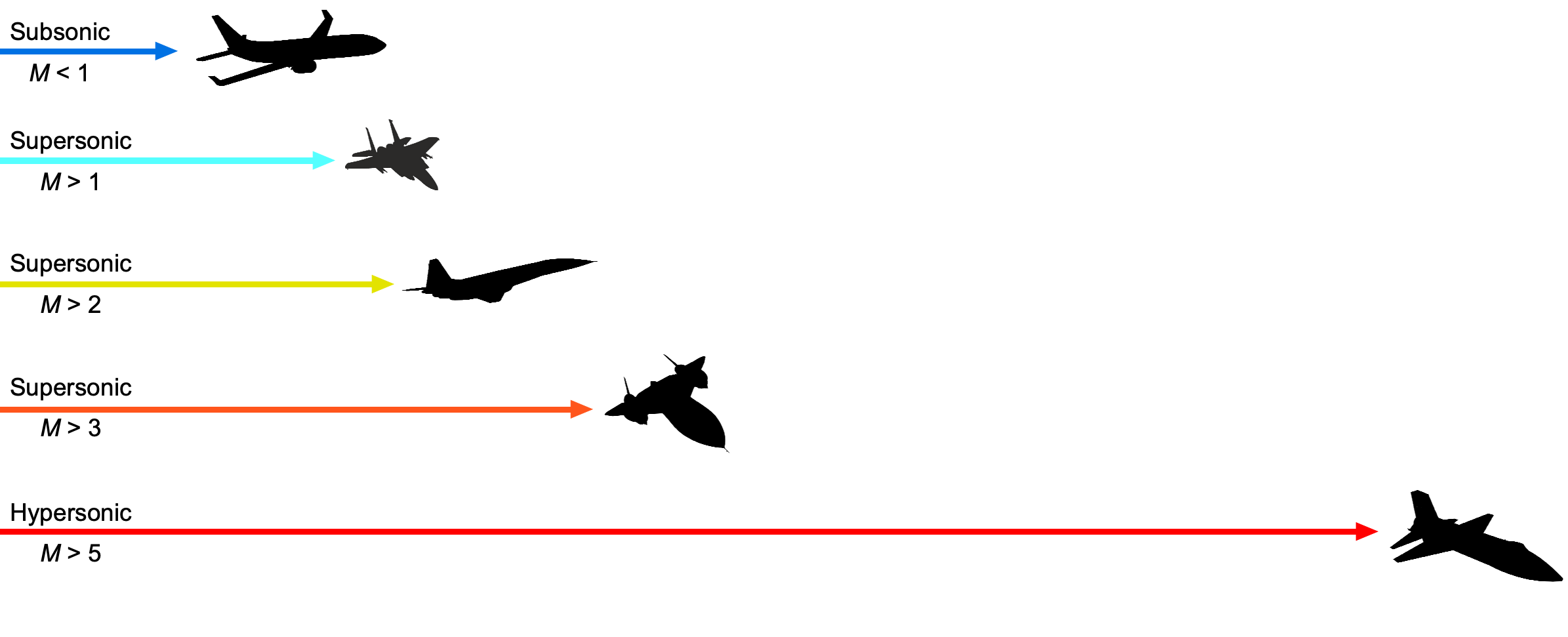
Hypersonic flight is generally defined as speeds at or beyond Mach 5. However, unlike what happens as the aircraft approaches Mach 1, there are no distinctive changes in the flow characteristics as an aircraft reaches hypersonic Mach numbers. Such high Mach numbers have only been achieved by rockets, re-entry spacecraft, and special high-altitude research aircraft. Indeed, every spacecraft that re-enters the Earth’s atmosphere will travel at hypersonic speeds. The image of a flaming spacecraft streaking through the upper atmosphere at Mach 20 is no exaggeration, as it accurately reflects the real aerodynamic and thermal environment. Theodore von Kármán was one of the first to analyze the problems of hypersonic flight, stating: “At such speeds, even in rarified air, the surface will be heated to the temperatures none of the known materials can withstand. The problem of the thermal barrier is much more complicated than the problem of the sound barrier.”
From an engineering perspective, hypersonics is best understood as a multidisciplinary regime where fluid mechanics, thermodynamics, and chemical kinetics become tightly coupled. As vehicles reach hypersonic Mach numbers, new aerodynamic and technical challenges emerge. These include the proximity of strong shock waves to the surface, extreme aerodynamic heating, complex interactions between the airframe and engine, viscous effects, high-temperature chemical reactions, and material erosion. These conditions demand specialized design strategies, particularly in shaping the airframe to manage heat and maintain control. Hypersonic vehicles often feature blended bodies with tightly integrated propulsion systems, in stark contrast to the separate airframe and engine architectures of subsonic and supersonic aircraft.

Hypersonic flow is typically considered to begin around Mach 5, but this threshold is not sharply defined. A better indicator of hypersonic effects is the emergence of complex thermochemical phenomena. As a vehicle travels faster, the kinetic energy of the incoming air becomes large enough that, when decelerated near the body, it transforms into internal energy, dramatically increasing the thermal and chemical activity within the gas. In more detail, the effects encountered at hypersonic Mach numbers include, but are not limited to, the following:
- The Mach angle becomes very small, causing shock waves to sweep back tightly toward the vehicle’s surface. These shocks can interact with the surface boundary layers, often triggering flow separation. Boundary layers at hypersonic speeds may be laminar but are relatively thick, and so the flow field becomes highly complex because of shock-boundary layer interactions.
- The proximity of shocks to the surface and the presence of viscous boundary layers cause intense aerodynamic heating. Even high-temperature materials, such as aluminum and titanium, commonly used in supersonic aircraft, will not survive unprotected in hypersonic environments.
- The surface boundary layers are relatively thick, introducing significant viscous interactions with the predominantly outer inviscid flow. This viscous/inviscid interaction effectively displaces the outer streamlines, causing the vehicle to appear aerodynamically larger or differently shaped than its actual geometry.
- The external flow strongly couples with the propulsion system. Effective hypersonic vehicle design requires shaping the vehicle to precompress incoming air before it reaches the engine, leading to a need for highly integrated airframe-propulsion configurations.
- Shock waves at hypersonic speeds are extremely strong, resulting in substantial temperature increases within the flow. These high temperatures can initiate chemical reactions in the air, such as dissociation and ionization, necessitating the use of thermochemical models to predict the aerodynamic behavior accurately.
- Sonic booms at Mach numbers greater than 5 are exceptionally intense. At hypersonic speeds, the resulting ground-level disturbances, which will likely exceed 130 dB(A), will be strong enough to harm human hearing and damage structures.
These challenges are not merely academic. They define the physical boundaries within which hypersonic vehicles must be designed, tested, and operated. Overcoming them requires a multidisciplinary approach that spans aerodynamics, thermodynamics, materials science, and flight control systems.
Hypersonic technologies may also be poised to revolutionize military systems by enabling vehicles that travel at speeds exceeding Mach 5 and have high maneuverability, making them nearly impossible to intercept. Platforms like hypersonic glide vehicles and cruise missiles offer rapid global strike capabilities but present significant challenges in terms of thermal protection, guidance, and propulsion. Several countries are investing heavily in these systems, prompting parallel efforts in counter-hypersonic defense using advanced sensors and interceptors. On the civil side, hypersonic flight remains a much longer-term ambition, with research targeting Mach 5 passenger aircraft that could drastically reduce intercontinental travel times. However, significant hurdles remain in developing propulsion systems, heat management, and regulatory approval. Sonic booms from civil hypersonic flight vehicles, if realized, will be extreme and not tolerated by the general public. Hence, the need for boom mitigation introduces further constraints in their design.
Learning Objectives
- Appreciate the unique aerodynamic and thermal challenges faced by aircraft operating at hypersonic speeds, including strong shock interactions, high aerodynamic heating, and high temperature “real gas” effects.
- Know how to apply analytical techniques, such as Newtonian and shock-expansion theories, to determine aerodynamic properties of bodies in hypersonic flow conditions.
- Develop an understanding of the role of high-temperature gas dynamics, boundary layer behavior, thermal protection strategies, and air-breathing engine concepts, such as scramjets, in the design and analysis of hypersonic vehicles.
History of Hypersonic Flight Vehicles
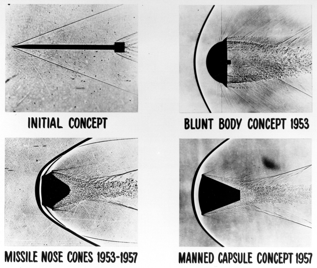
The challenges associated with hypersonic flight first became evident during the early Cold War, when post-WWII ballistic missile development pushed vehicles into Mach 5 and higher regimes. To achieve an intercontinental range, these missiles had to exit the atmosphere and re-enter it near the target location. Based on the highly pointed German V-2 designs, the missile experienced intense aerodynamic heating and shock wave compression, leading to structural failure; it often melted entirely during its descent. These events highlighted the extreme aerodynamic and thermal loads encountered in hypersonic flight, which have become the subject of extensive research.
The answer to this aerodynamic heating problem, based on NACA research by H. Julian Allen and Alfred Eggers, was an approach opposite to what was expected based on conventional aerodynamic wisdom, which suggested making the nose of the missile much more blunt and rounded, as shown in the schlieren visualization images below. This “blunt body” design created a shock wave that stood off the nose, causing a boundary layer to flow over the nose cone’s surface and preventing the excessive heat of re-entry from melting the structure. In contrast, pointed nose shapes allowed the shock wave to interact with the surface through a boundary layer that was too thin to provide significant thermal protection. Tests with the modified missiles confirmed the validity of this method, although the nose still required materials resistant to high temperatures.
The information gained about high-speed flight and hypersonics through wind tunnel tests and flight tests significantly contributed to the development of the Mercury, Gemini, and Apollo spaceflight programs. Flight test work on hypersonics was first conducted by the U.S. Air Force and NASA during the 1950s. The X-15 research aircraft flew for nearly ten years from 1959. They set the world’s unofficial speed and altitude records of 4,520 mph (Mach 6.7) and 354,200 feet during a program to investigate all aspects of piloted hypersonic flight.
The X-17 was a missile program that utilized a three-stage rocket to propel the nose section to conditions between Mach 10 and 20 in the lower atmosphere. The nose cones survived briefly before vaporizing, but long enough for valuable measurements to be made. Ultimately, the solution to minimizing kinetic heating effects on re-entry vehicles was also to use ablative materials to help shed the heat buildup.
During the 1980s, NASA began considering a single-stage hypersonic flight vehicle as a replacement for the Space Shuttle. The National Aerospace Plane (NASP) was intended to take off from a standard runway used by airliners. Once the aircraft had reached sufficient airspeed, the scramjet engines would power it into hypersonic flight. Finally, a rocket system would take the NASP into orbit. The NASP eventually became the Rockwell X-30 research vehicle. While the project did not reach the flight stage, a one-third-scale demonstrator, the X-43, was built. Three were built. The first was destroyed after an in-flight malfunction, but the other two flew successfully, with the scramjet operating for approximately 10 seconds.

Since the X-43A’s flights in the early 2000s, hypersonic development has accelerated worldwide. The U.S. X-51A Waverider achieved sustained scramjet-powered flight at Mach 5.1 for over 200 seconds, while Stratolaunch’s reusable Talon-A vehicle reached hypersonic speeds and completed recovery missions by 2025. Venus Aerospace demonstrated a rotating detonation rocket engine for its Mach 9-capable Stargazer platform. Australia’s Hypersonix has developed the hydrogen-fueled SPARTAN scramjet for the Delta-Velos vehicle, designed to achieve speeds of up to Mach 12. Meanwhile, Switzerland’s Destinus and China’s hypersonic aircraft efforts are aimed at commercial applications, with India also entering the arena through successful hypersonic missile tests. These advances signal growing global investment in reusable, high-speed flight technologies across defense, research, and future commercial transport.

Hypersonic Flow Modeling
Hypersonic aerodynamics introduces physical effects beyond those encountered in subsonic or supersonic regimes. As flight speeds exceed Mach 5, the flows are increasingly dominated by strong shock waves, extreme post-shock temperatures, thick boundary layers, and significant thermal loads. The physical complexity of hypersonic flow makes detailed analysis challenging, especially in early-stage design or conceptual studies. Strong shocks, entropy[1] gradients, viscous interactions, and chemistry effects contribute to this difficulty. To this end, engineers often rely on simplified models that approximate surface pressures and aerodynamic forces without solving the complete set of governing flow equations, which are, for the most part, impractical.
Shocks at High Mach Numbers
In supersonic flow, a wedge-shaped body generates an oblique shock wave at its leading edge, as shown in the figure below. Unlike a normal shock, which stands perpendicular to the flow, an oblique shock forms at an angle relative to the surface, allowing the flow to remain supersonic downstream. As the freestream Mach number increases, the shock angle decreases, bringing the shock closer to the surface.
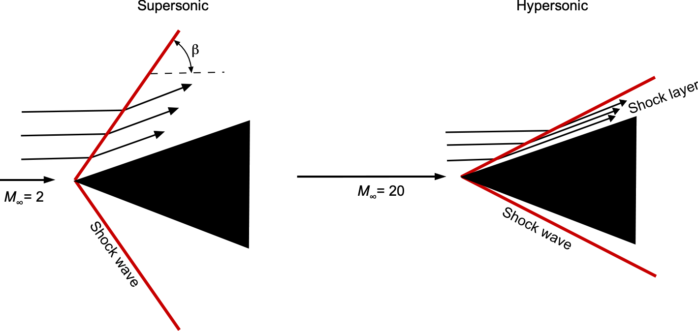
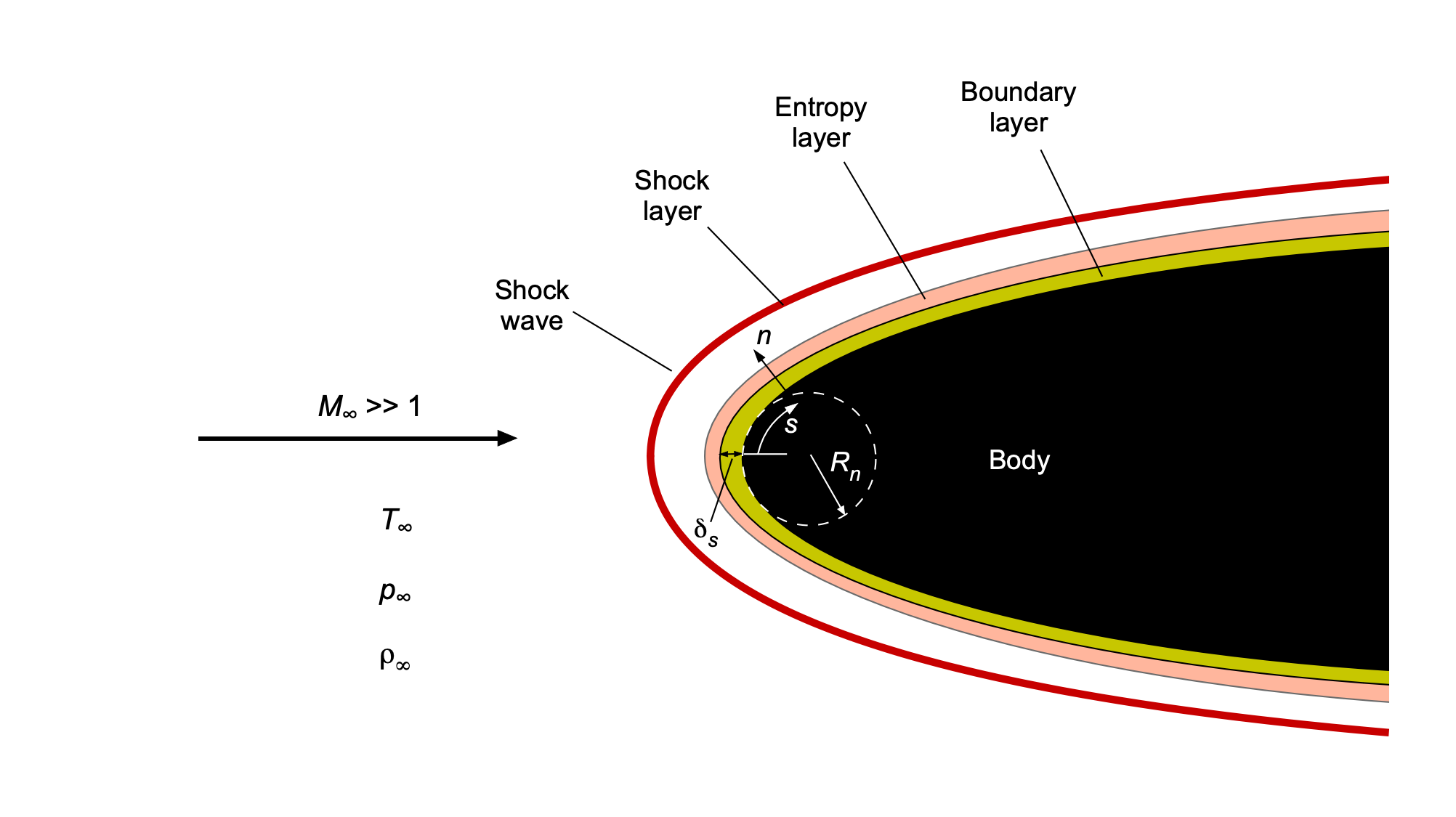
At hypersonic speeds, this shock standoff distance becomes very small, and the region between the shock and the body surface is often referred to as a shock layer. This shock layer can be extremely thin in hypersonic flow over slender bodies, particularly at high altitudes where the Reynolds number is low. Under such conditions, the shock layer may interact with or merge into the boundary layer, forming a fully viscous shock layer. This complex regime has a significant influence on heat transfer, surface pressures, and overall aerodynamic characteristics.
Slender Bodies
When a supersonic flow encounters a sharp compression surface, such as a wedge or ramp, the flow is deflected through an angle  relative to the incoming stream, as shown in the figure below. In response, an oblique shock forms at an angle
  with respect to the upstream flow direction. The relationship between the deflection angle , the shock angle , and the upstream Mach number
  is described by the ––
 relation, a fundamental expression in compressible flow theory. As discussed in the previous chapter, this relationship is given by
(1) 
where  is the ratio of specific heats, which is 1.4 for air.

For a given Mach number and deflection angle, a weak shock and a strong shock. The weak solution is typically observed in external aerodynamic flows, as it produces lower pressure and allows for temperature increases, enabling the flow to remain supersonic downstream of the shock. Although mathematically valid, the strong solution is usually associated with internal or confined flows and is rarely seen in freestream conditions.
At high Mach numbers and small deflection angles, the shock angle is only slightly greater than the deflection angle , resulting in a thin shock layer that hugs the body. However, as the deflection angle increases toward a critical value, the oblique shock becomes increasingly intense and eventually detaches from the surface. Beyond this point, the shock detaches, forming a curved bow shock ahead of the body. This shock detachment phenomenon is particularly significant in hypersonic flow, where even slight changes in body geometry can dramatically alter surface pressure and thermal loads.
The onset of shock detachment can be examined using the –– relation, which links the upstream Mach number  , the flow deflection angle , and the shock angle . For a given , there exists a maximum allowable deflection angle
  beyond which no attached oblique shock solution exists. This critical angle depends on the Mach number and the specific heat ratio , marking the transition from an attached oblique shock to a detached bow shock. To maintain shock attachment and predictable pressure distributions, designers must ensure that surface deflections stay below this threshold. For blunt geometries or large deflection angles, detached shocks and intense local heating are unavoidable and must be accounted for in the thermal protection system design.
Blunt Bodies
In contrast to slender bodies that produce oblique shocks, blunt bodies generate normal shock waves when the incoming supersonic flow is brought to rest abruptly, typically at a stagnation point. This occurs, for instance, at the nose of a reentry vehicle, as shown in the figure below, where the flow cannot turn smoothly around the body as it does over a wedge. Instead, the air must decelerate to near-zero velocity over a very short distance. In supersonic or hypersonic regimes, the only physically admissible way for this to occur is through the formation of a detached bow shock standing off from the surface. This strong normal shock induces a sudden and severe rise in pressure and temperature, initiating the thin but highly energetic shock layer that envelops the front of the vehicle.
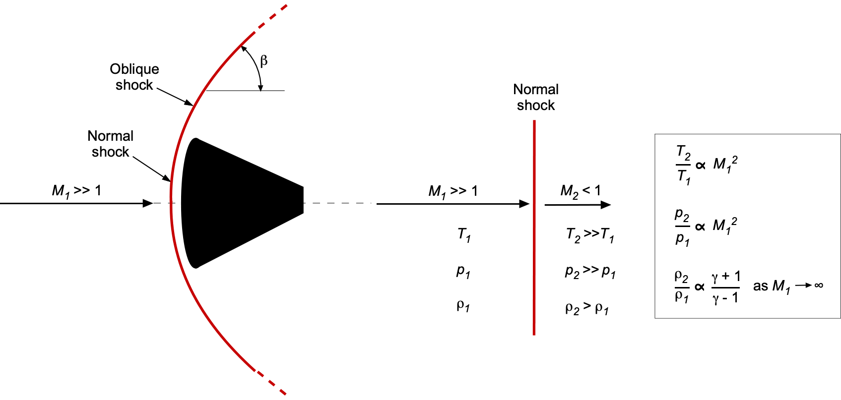
Notice that the shock is normal only on the centerline, where the freestream stagnates directly. It is oblique elsewhere, wrapping around the body and becoming more inclined as it moves further from the centerline. Across an oblique shock, only the velocity component normal to the shock is compressed, while the tangential component remains unchanged. The governing equations for pressure, temperature, and density changes are still those of a normal shock, but they apply to the normal component of the upstream Mach number, i.e.,
(2) 
where is the freestream Mach number and is the local shock angle between the flow and the shock front. The downstream Mach number is computed from the turned flow, taking into account both components. The flow behind the shock remains supersonic if the shock is weak (i.e., associated with a small flow deflection), or subsonic if the shock is strong (i.e., associated with a large deflection).
A normal shock wave abruptly increases pressure, temperature, and density, accompanied by a sharp reduction in Mach number. As the upstream Mach number increases, these thermodynamic changes become more pronounced. In the strong-shock limit ( ), the post-shock pressure and temperature scale approximately with
  . For a calorically perfect gas, the leading-order approximations for the temperature and pressure ratios across a normal shock are
(3) 
where is the ratio of specific heats, which is 1.4 for air. These relations are valid as long as the post-shock temperature remains within the range where the gas can be considered calorically perfect, generally below 1,000–1,500 K for air.
These expressions highlight the sensitivity of post-shock conditions to the freestream Mach number. Even moderate increases in can significantly increase downstream pressure and temperature. In hypersonic flow, where Mach numbers are extremely high, normal shocks produce steep thermal gradients that significantly influence boundary layer behavior and surface heating. A key consequence of this heating is the dramatic rise in convective heat flux experienced by the surface of a hypersonic vehicle. Empirically, the convective heat flux  scales approximately as the cube of the freestream velocity, i.e.,
(4) 
Given that the velocity is related to the Mach number by  , and the speed of sound is
  , assuming constant ambient density and temperature leads to the simplified scaling
(5) 
This result implies that doubling the Mach number results in an approximate eightfold increase in convective heating. Such sensitivity highlights the importance of designing accurate thermal protection systems for hypersonic flight regimes.
Several important limiting cases illustrate this behavior. At the stagnation streamline,  , so
, so  , and the result is a full normal shock. As the shock angle decreases with increasing distance from the centerline,
  becomes smaller and the shock weakens. In the limit as
  , the shock becomes a Mach wave. Consequently, the strength of the shock, and therefore the heating and pressure rise, varies continuously over the body’s surface. The highest heating and pressure occur near the nose, where the shock is nearly normal and the freestream kinetic energy is most effectively converted into internal energy. This has direct consequences for aerodynamic loading and the design of thermal protection systems.
Shock Layers and Boundary Layer Behavior
As previously described, at hypersonic speeds, the bow shock formed at the nose of a blunt body detaches and stands off from the surface, enclosing a narrow region of compressed, decelerated gas known as the shock layer, as shown in the figure below. Near the nose, this shock layer can be quite thin relative to the overall body size, though it contains steep gradients in pressure, temperature, density, and velocity. As the freestream flow passes through the bow shock, it undergoes an abrupt rise in pressure and temperature, accompanied by a rapid deceleration, especially along streamlines near the stagnation region. The balance between shock curvature and body shape governs the geometry of the shock layer. Near the nose, where the shock is nearly normal to the surface, the post-shock flow slows significantly, and the viscous and thermal layers are relatively thick. Further downstream, as the shock becomes increasingly oblique, the post-shock velocity remains higher and the shock layer narrows, conforming more closely to the body’s surface.
When the surface deflection angles are small and the freestream Mach number is high, the local flow can often be modeled using the thin shock-layer approximation. This approach assumes that variations in flow properties occur primarily in the direction normal to the surface, rather than along it, i.e.,
(6) 
where  is the surface-normal direction, and
  is tangential. This simplification reduces the governing equations, making it easier to estimate surface pressure and thermal loads.
Near the stagnation point, a useful scaling for the shock layer thickness is
(7) 
where  is the nose radius of curvature and
  is the freestream Mach number. As the Mach number increases, the shock layer becomes thinner and more compressed, a defining feature of hypersonic flow.
In this regime, the viscous boundary layer behaves differently than in subsonic or low-supersonic flows. It grows more rapidly, driven by strong shock compression, elevated surface temperatures, and increased gas viscosity. As a result, the boundary layer becomes dynamically significant and may interact with shock waves, affecting the overall flow structure.
Unlike lower-speed flows, where boundary layers tend to transition quickly to turbulence, hypersonic boundary layers often remain laminar for longer distances. An approximate scaling for the laminar boundary layer thickness  over a flat plate at hypersonic speeds is
(8) 
where  is a characteristic length,
  is the Reynolds number based on distance from the leading edge, is the specific heat ratio, and is the freestream Mach number. In the high-Mach limit, this simplifies to
(9) 
depending on wall temperature and thermal boundary conditions. These scalings highlight how boundary layer thickness increases more rapidly with Mach number than in incompressible flows, making it a dominant factor in aerodynamic performance and heating.
The rise in surface pressure in high-speed flow is commonly expressed using the pressure coefficient, i.e.,
(10) 
where  is the wall (surface) pressure and
  is the freestream dynamic pressure. At the stagnation point, where the flow comes to rest and the shock is strongest, the pressure coefficient reaches its maximum value, denoted
  . This value can be estimated using normal shock relations from the post-shock pressure
  .
.
In regions with steep surface deflection, such as the nose of a blunt body, the incoming flow behaves as if it were a direct impact. In this limit, the pressure coefficient approaches the Newtonian approximation
(11) 
where is the angle between the freestream direction and the surface normal. This model, although approximate, offers an effective method for estimating surface pressure distributions in hypersonic flow over blunt geometries.
Check Your Understanding #1 – Analysis of the nose of a reentry vehicle
Consider a reentry vehicle traveling at a freestream Mach number of = 10 through the upper atmosphere at an altitude of approximately 40 km. The vehicle has a hemispherical nose with a radius of curvature = 0.5 m. At this altitude, the freestream conditions are:  = 0.003996 kg/m
 ,
,  = 250 K, and
  = 2,871 Pa. Assume the gas behaves as a perfect gas with a specific heat ratio of = 1.4 and gas constant
  = 287 J/(kg K).
Show solution/hide solution.
This example focuses on the leading nose geometry of the vehicle, where hypersonic compression effects and shock-layer behavior are most intense. The surface pressure and pressure coefficients can be predicted at key locations along the nose using the thin shock-layer approximation and Newtonian theory. The isentropic relation gives the freestream velocity for a perfect gas, i.e.,
![\[ V_\infty = M_\infty \sqrt{\gamma R T_\infty} \]](https://eaglepubs.erau.edu/app/uploads/quicklatex/quicklatex.com-d11c973543c45157d4c304526fbc649b_l3.svg "Rendered by QuickLaTeX.com")
Substituting the values gives
![\[ V_\infty = 10 \sqrt{1.4\, 287\, 250} = 3,170 \text{ m/s} \]](https://eaglepubs.erau.edu/app/uploads/quicklatex/quicklatex.com-7637c3f3e179894c811c65f0b91e4993_l3.svg "Rendered by QuickLaTeX.com")
The dynamic pressure is calculated using
![\[ q_\infty = \frac{1}{2} \rho_\infty V_\infty^2 = \frac{1}{2} \, 0.003996 \, (3170)^2 \approx 2.01 \times 10^4 \text{ Pa} \]](https://eaglepubs.erau.edu/app/uploads/quicklatex/quicklatex.com-3ff72502f021e42bdc6b754adc748f3a_l3.svg "Rendered by QuickLaTeX.com")
To estimate the pressure at the stagnation point, the normal shock approximation for high Mach numbers can be used, i.e.,
![\[ \frac{p_2}{p_\infty} = \frac{2\gamma}{\gamma + 1} M_\infty^2 - \frac{\gamma - 1}{\gamma + 1} = \frac{2.8}{2.4} \, 100 - 0.167 = 116.5 \]](https://eaglepubs.erau.edu/app/uploads/quicklatex/quicklatex.com-4e1b21147046f65a02bd5e2a88f60c25_l3.svg "Rendered by QuickLaTeX.com")
so that
![\[ p_w = 116.5 \, p_\infty \approx 3.34 \times 10^5 \text{ Pa} \]](https://eaglepubs.erau.edu/app/uploads/quicklatex/quicklatex.com-99c01a5a97188485b6f1669c83fada5b_l3.svg "Rendered by QuickLaTeX.com")
The stagnation-point pressure coefficient is then
![\[ C_{p,0} = \frac{p_w - p_\infty}{q_\infty} = \frac{3.34 \times 10^5 - 2871}{2.01 \times 10^4} = 15.5 \]](https://eaglepubs.erau.edu/app/uploads/quicklatex/quicklatex.com-68c8d7ca5a5eb068dd0bee22e71203b2_l3.svg "Rendered by QuickLaTeX.com")
To estimate the pressure at an off-stagnation location, say  , the Newtonian pressure approximation can be used, i.e.,
![\[ C_p(\theta) = C_{p,0} \cos^2 \theta = 15.5 \, \cos^2(45^\circ) = 15.5 \, 0.5 = 7.75 \]](https://eaglepubs.erau.edu/app/uploads/quicklatex/quicklatex.com-586fadc56e1ac1799e95a5996dadc415_l3.svg "Rendered by QuickLaTeX.com")
The local surface pressure is
![\[ p_w(\theta) = p_\infty + C_p(\theta) \, q_\infty \]](https://eaglepubs.erau.edu/app/uploads/quicklatex/quicklatex.com-0d4217e193be61dfd0847b8584852bee_l3.svg "Rendered by QuickLaTeX.com")
so that
![\[ p_w(45^\circ) = 2871 + 7.75 \, 2.01 \times 10^4 \approx 1.58 \times 10^5 \text{ Pa} \]](https://eaglepubs.erau.edu/app/uploads/quicklatex/quicklatex.com-c022bf97c10ad5d5925785fd7536fa88_l3.svg "Rendered by QuickLaTeX.com")
Finally, the stagnation-point shock-layer thickness can be estimated using
![\[ \delta_s \ \propto \ \frac{R_n}{M_\infty^2} = \frac{0.5}{100} = 0.005 \text{ m} = 5 \text{ mm} \]](https://eaglepubs.erau.edu/app/uploads/quicklatex/quicklatex.com-560054e904fbaea011b62bcef6a299f4_l3.svg "Rendered by QuickLaTeX.com")
These results demonstrate key features of hypersonic flow over blunt reentry geometries, including strong compression and thin shock layers.
Entropy Gradients and Flow Interactions
An increase in entropy typically means that energy is lost to irreversible processes, such as shock compression and viscous dissipation, in aerodynamic flows. Across a shock wave, entropy always increases because of the irreversible nature of the compression process. Across a curved bow shock, entropy increases significantly, especially near the stagnation streamline. This behavior creates a high-entropy layer near the body centerline, displacing lower-entropy gas outward. The result is a distortion in the outer flow and the surface boundary layer, which are relatively thick in hypersonic flows.
A viscous interaction parameter is used to characterize the influence of viscous effects in hypersonic flow, particularly in the coupling between the boundary layer and the outer inviscid field. The thick boundary layer in hypersonic flow can exert a significant displacement effect on the inviscid flow outside the boundary layer, causing a given body shape to appear substantially thicker than it actually is. Two related but distinct forms are commonly used, namely  and
and  . The parameter is defined using surface heat transfer as
(12) 
where  is the wall heat flux, is the freestream density, and
  is the freestream velocity. This dimensional form quantifies the relative magnitude of energy extracted from the flow by conduction at the wall. A larger value of indicates stronger viscous interaction and greater boundary-layer displacement effects.
In contrast, is a nondimensional scaling parameter defined in terms of freestream properties and Reynolds number as
(13) 
where is the freestream Mach number and  is the Reynolds number based on a characteristic length and freestream viscosity
  . This form of the interaction parameter is often used to classify flow regimes by the strength of viscous interaction. Values of less than one indicate weak interaction, values near unity indicate moderate interaction, and larger values of greater than 3 correspond to strong interaction with significant effects on shock shape, boundary layer growth, pressure gradients, as well as lift and drag.
Boundary Layer Scaling and Surface Heating
The most dominant aspect of high temperatures in hypersonic flow about a body is the resultant high heat-transfer rates to the surface. Indeed, thermal loads are a primary design constraint in hypersonic vehicles. The kinetic energy of a high-speed flow is dissipated by the influence of friction within a boundary layer. The extreme viscous dissipation within hypersonic boundary layers can create very high temperatures. The boundary layer in hypersonic flow is generally thicker than in subsonic or transonic conditions because of compressibility and elevated viscosity values at higher temperatures. For a laminar boundary layer over a flat plate, the thickness scales as
(14) 
where  is the distance from the leading edge and
  is the dynamic viscosity. In hypersonic conditions, temperature-dependent viscosity leads to additional thickening, particularly under cold-wall assumptions.
Near the stagnation point, the kinetic energy of the freestream is converted into internal energy, resulting in intense surface heating. A representative scaling law for stagnation-point heat flux is
(15) 
highlighting the strong cubic dependence on velocity. Even modest velocity increases can cause dramatic rises in heat flux, necessitating robust thermal protection. For adiabatic[2] surfaces, the recovery temperature indicates the effective surface temperature from frictional heating. For a laminar boundary layer, the recovery temperature is approximately
(16) 
assuming a recovery factor near unity. Heat is transferred into the surface if the wall temperature is below this value.
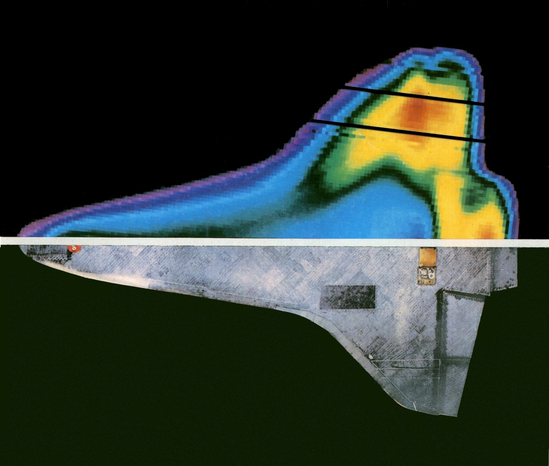
The resulting kinetic heating on a hypersonic flight vehicle can raise its surface temperatures to several thousand oK, especially in regions such as stagnation points and along the leading edges. These extreme thermal loads severely constrain materials selection, structural design, and aerodynamic shaping. Conventional metals like aluminum and titanium quickly lose strength or melt at such temperatures, making them unsuitable for exposed surfaces. Hypersonic vehicles must incorporate specialized thermal protection systems (TPS) and high-temperature structural materials to withstand these conditions. Extensive studies were conducted to measure the temperatures on the Orbiter during re-entry, as shown in the figure below. Highest temperatures[3] reached 1,544 oC (2,840 oF.) on the reinforced carbon/carbon TPS surfaces in the nose area, as well as along the leading edges of the wings.
Depending on the size, shape, and mission profile of a hypersonic flight vehicle, several TPS strategies may be employed:
- Insulating tiles and blankets, such as those used on the Space Shuttle, provide reusable protection for lower-heating areas. These materials rely on low thermal conductivity and bulk insulation rather than surface ablation.
- Ablative coatings, such as phenolic-impregnated carbon or silicone-based materials, are used for short-duration, high-heat flux scenarios (e.g., atmospheric reentry). These materials absorb heat through chemical decomposition and erosion, carrying energy away from the surface.
- Refractory composites, including carbon-carbon and reinforced carbon-silicon carbide, are often used for leading edges and nosecones. These materials retain mechanical integrity at extremely high temperatures and are suitable for repeated heating cycles.
- Actively cooled structures, though more complex, may be necessary for sustained hypersonic cruise vehicles. These involve circulating coolants through internal channels to remove heat from critical components.
High-Temperature Gas Behavior
As hypersonic conditions are approached, air initially behaves as a compressible but still ideal gas. In this regime, many classical thermodynamic tools remain applicable. However, at post-shock temperatures exceeding approximately 2,000 K, the gas begins to exhibit high-temperature, “real gas” behavior because of the activation of internal molecular energy modes and chemical transformations, as illustrated in the figure below.
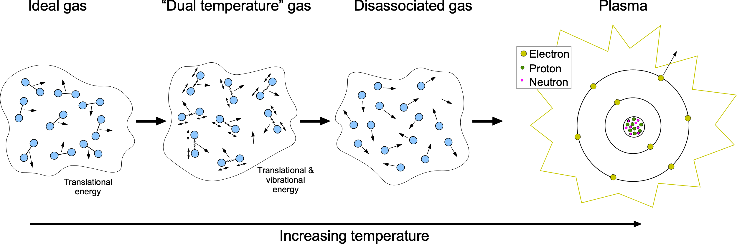
This transition unfolds in stages, each corresponding to increasing levels of kinetic energy in the flow:
- Ideal gas: According to the equipartition theorem, internal energy is shared equally among all active degrees of freedom, with each contributing /2 per mole. For a diatomic gas at room temperature, its kinetic energy and, hence, its temperature result from three translational degrees of freedom and two rotational degrees of freedom. Vibrational modes are inactive at these temperatures.
- Vibrational Excitation: Diatomic molecules such as
 and
and  begin to vibrate internally as the flow temperature increases. This vibrational internal energy is not captured by the standard temperature, effectively introducing a second mode of thermal behavior.
 - Dissociation: At higher temperatures, molecular bonds begin to break. For example, dissociates into individual oxygen atoms near 2,000 K, while dissociates around 4,000 K. This bond-breaking consumes energy and alters the thermodynamic properties of the air.
- Ionization: With even more energy input, atoms begin to lose electrons, producing a plasma, which is a partially ionized gas containing free electrons and ions. For instance, a typical oxygen atom with 8 protons, 8 neutrons, and 8 electrons may lose one of its electrons, resulting in a charged species.
- Radiative Heat Transfer: At extreme temperatures, typically in the upper range of hypersonic reentry, radiative heat transfer can dominate over conduction and convection. This regime marks the most severe thermal environment currently encountered in aerospace applications.
These thermochemical processes increase the internal energy storage capacity of the gas and alter its specific heat capacities ( and
and  ), which become temperature-dependent. As a result, the perfect gas assumption breaks down. In some cases, chemical equilibrium can be assumed; in others, nonequilibrium models are required, especially near shock layers and within high-temperature boundary layers where finite-rate chemistry is significant. Therefore, understanding these real gas effects is critical in predicting heat transfer rates, boundary layer behavior, and surface pressure distributions. They become crucial in atmospheric reentry systems where post-shock temperatures generally exceed several thousand oK.
Hypersonic “Newtonian” Theory
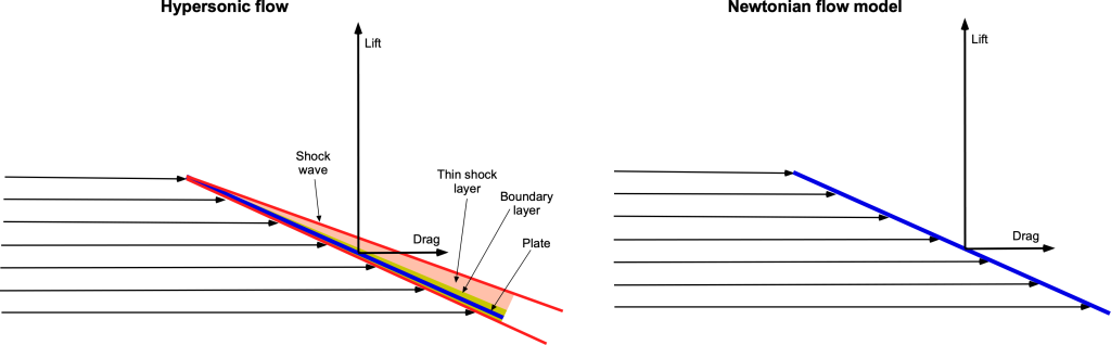
Like all aspects of flight vehicle design, the ability to predict quantitatively aerodynamic forces for the right physical reason is fundamental. To this end, a relatively parsimonious but validated method must often be used, providing the necessary focus to establish initial designs from which more detailed analysis can follow. A widely used approximation in hypersonic aerodynamics is Newtonian impact theory. Although it does not account for boundary layer effects, viscous heating, or “real gas” (high-temperature) behavior, it effectively estimates surface pressures based on local flow deflection. The core idea is geometric and kinematic: the freestream flow is treated as a stream of particles that transfer momentum normal to the surface upon impact. This leads to a pressure distribution that depends only on the local surface inclination angle relative to the freestream.
Isaac Newton was unaware of shock waves, supersonic, or hypersonic flows. Still, in his Principia of 1687, he hypothesized some simple hydrodynamic principles, which have seen application to hypersonic flows in recent decades. Newton proposed that fluid flow forces exerted on a surface consisting of a uniform stream of “particles” in which the time rate of change of the normal component of the momentum of each particle would be transferred to the plate, whereas the tangential component would be preserved. He assumed that the upper surface always remains in the “shadow” of the flow and is hence uninfluenced by the freestream flow.
Newtonian Flow on a Slender Body
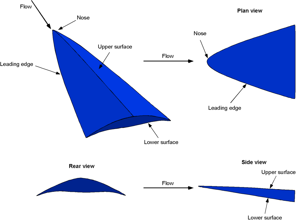
The figure below illustrates a hypersonic flow impinging on a thin body, resulting in a shock wave near the surface and a thin shock layer. In a supersonic flow, disturbances cannot be propagated upstream, so there is no streamline curvature as the flow approaches the wing. Indeed, the resulting flow field bears a remarkable resemblance to that proposed by Newton more than three centuries ago, despite the physical disparity in detail. Indeed, although the so-called Newtonian aerodynamics theory is flawed for several reasons, it remains a reasonably good model for describing the lift and drag of bodies in hypersonic flows.
In the context of hypersonic lift and drag estimation, Newtonian theory can be applied to slender flat plates or symmetric wedges at an angle of attack. The central assumption is that only the windward surface makes a significant contribution to pressure forces. At the same time, the leeward side is effectively pressure-less, which is a valid approximation in high Mach number regimes. The surface pressure coefficient is given by
(17) 
where is the angle between the local surface normal and the freestream direction.
Consider a symmetric wedge of half-angle  flying at an angle of attack
  . Newtonian theory can provide an approximate method for estimating the aerodynamic pressure distribution in hypersonic flow. The inclination angles of the upper and lower surfaces relative to the freestream are
  and
and  , respectively. According to the Newtonian theory, the local pressure coefficients on each surface are
(18) 
These pressure forces act normally on the wedge surfaces and are decomposed into lift and drag components by projection in the direction of the freestream. Assuming unit span and chord length  , the total lift and drag coefficients are given by
(19) 
These expressions highlight the nonlinear dependence of aerodynamic forces on both the angle of attack and the wedge geometry. The theory is most accurate for slender wedges at high Mach numbers, where pressure forces dominate over viscous effects and shock-layer interactions. Despite its simplicity, the Newtonian theory remains useful for preliminary estimates of aerodynamic loads in hypersonic design.
Consider also a flat plate at an angle of attack , where the surface is uniformly inclined at  . Applying Newtonian theory and resolving the normal pressure force into freestream-aligned components, the resulting aerodynamic coefficients are
(20) 
The corresponding lift-to-drag ratio is
(21) 
Validation
While the Newtonian “hypersonic” theory is elementary, at least in terms of predicting lift and drag coefficients, the question is how well it works in practice, i.e., can it be used to predict anything useful? To this end, the results shown in the figures below compare the Newtonian theory with NASA wind tunnel measurements on a hypersonic body at Mach numbers of 6 and 10. Measurements are available for angles of attack of -5.5o to 35o at Mach numbers from 1.5 to 10.
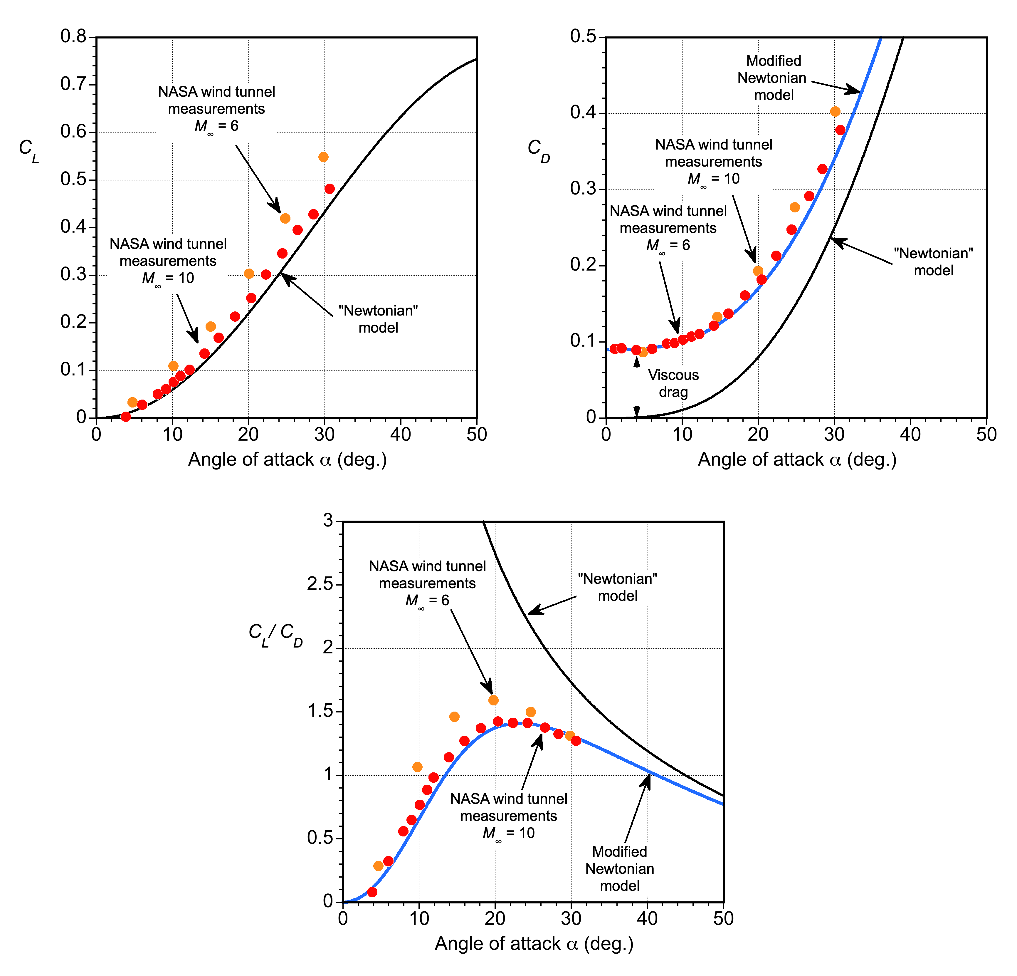
Despite its simplicity, the Newtonian theory is in remarkable agreement with the measurements. The drag is underpredicted because the Newtonian theory does not account for wave drag and viscous effects. However, the drag equation can be modified empirically to
(22) 
where  is the wave drag and
  is the viscous shear stress drag, both of which will depend on the specific body shape. One approximation used for the wave drag of a body in hypersonic flow is
(23) 
which is attributed to Nonweiler. Notice that for  = 10 then
  = 0.02. Furthermore, it is often assumed that high-speed bodies have a viscous friction drag proportional to their wetted area times a known constant, i.e., the skin friction coefficient,
  , which comes from boundary layer theory or the von Driest equation, i.e.,
(24) 
Therefore, approximately, for the upper and lower surfaces, then
(25) 
Naturally, there are flow interference effects to consider as well. In this case, a value of  aligns well with the wind tunnel measurements. The corresponding lift-to-drag ratio now becomes
(26) 
which again is seen to be in good agreement with the wind tunnel measurements. Notice that in the absence of viscous effects, the Newtonian theory becomes singular at exactly zero angle of attack, but this is of no practical significance.
It can be concluded that, despite its limitations, Newtonian “hypersonic” aerodynamics can still be used in some instances to provide reasonable estimates and initial approximations for aerodynamic lift and drag. Therefore, it can be helpful in conceptual design studies or in situations where a rapid assessment of the aerodynamic characteristics of a hypersonic vehicle is required.
Hypersonic Forces on General Shapes
Understanding how aerodynamic forces act on different shapes at hypersonic speeds is crucial for designing reentry vehicles. To this end, analytical results can be obtained for some common shapes, which help address certain design aspects. While slender bodies, such as cones, minimize drag, they suffer from intense surface heating. In contrast, blunt shapes like hemispheres endure much higher drag but provide critical thermal shielding by keeping the shock layer detached and away from the surface. This trade-off between aerodynamic efficiency and thermal survivability defines much of modern hypersonic design practice.
Hypersonic Cone
Consider a slender flight vehicle modeled as a cone with half-angle , moving at hypersonic speed through the atmosphere. Using the Newtonian impact theory, the pressure coefficient on the cone surface is approximated as
(27) 
The surface pressure becomes
(28) 
A differential ring element at axial position has radius  and surface area
(29) 
The axial (drag) component of the pressure force is
(30) 
Integrating over the cone from  to
to  , the total drag force is
(31) 
This result gives the total axial force on a slender cone, expressed in terms of dynamic pressure  , cone length , and cone half-angle . It provides a helpful estimate of hypersonic drag based on an idealized surface pressure distribution.
Hypersonic Blunt Body
A useful comparison can be made to the drag on a blunt body, such as a hemispherical forebody, where the pressure distribution is stronger and the shock layer is thicker because of the detached bow shock. Using the impact theory, the pressure coefficient on the stagnation point of a hemisphere is approximated by = 2. Assuming a uniform pressure distribution over the frontal area of the hemisphere (a simplification), the drag force becomes
(32) 
where  is the projected area of the hemispherical cap and is its radius.
To compare this with the slender cone, express the cone’s drag in terms of its base radius  , giving
(33) 
Now consider the ratio of blunt body drag to slender cone drag, i.e.,
(34) 
Because , this result becomes
(35) 
The outcome shows that the drag on a blunt hemisphere is significantly greater than that on a slender cone, especially for small , where  . The result quantitatively confirms the high aerodynamic drag associated with blunt reentry vehicles, which trade drag for reduced thermal loads.
Representative Drag Values in Hypersonic Flow
The table below summarizes approximate drag values for generic shapes in hypersonic flow, based on Newtonian or empirical formulations. Values are assumed to be idealized and are intended for comparative purposes.
| Shape | Drag Coefficient,  |
Expression (if applicable) | Notes |
|---|---|---|---|
| Flat Plate (normal) | 2.0 |  |
Maximum theoretical Newtonian drag |
| Flat Plate (45o inclined) | 1.0 |  o o |
Simplified oblique impact |
Cone ( o) o) |
 0.12 0.12 |
 |
Small-angle approximation |
| Hemisphere | 1.4–1.5 | Empirical | Common blunt-body approximation |
| Sphere | 1.1 |
Empirical | Typical high-Mach result |
Wedge ( o) o) |
0.47 |
 |
Symmetric wedge model |
| Blunted Cone | 0.5–1.5 | — | Depends on bluntness ratio |
| Reentry Capsule (Apollo-type) | 1.5 |
Empirical | Highly blunt shape for thermal effectiveness |
Check Your Understanding #2 – Hypersonic flow over a slender cone
A sharp, slender cone with a half-angle of = 10 is flying at Mach = 10 through the upper atmosphere. The freestream conditions are: air density = 0.0185 kg/m, static temperature = 270 K, ratio of specific heats = 1.4, and gas constant = 287 J/kg/K. The cone has a base diameter of
  = 0.5 m. Assume the surface is smooth and inviscid, and that Newtonian impact theory applies uniformly across the surface. Using Newtonian theory:
- Derive an expression for the surface pressure distribution as a function of the cone angle.
- Integrate this distribution to find the total axial force (drag) in terms of , , and .
- Derive the corresponding drag coefficient
 using the base area as the reference.
 - Evaluate the freestream velocity, dynamic pressure, cone length, total axial force, and drag coefficient for the given conditions.
Show solution/hide solution.
- The pressure coefficient on the surface of a slender cone using Newtonian theory is
![\[ C_p(\theta) = 2 \, \sin^2 \theta \]](https://eaglepubs.erau.edu/app/uploads/quicklatex/quicklatex.com-3a052c833ceaab29178e5a22b0a7f44b_l3.svg "Rendered by QuickLaTeX.com")
The surface pressure becomes
![\[ p(\theta) = C_p(\theta) \, q_\infty = 2 \, q_\infty \, \sin^2 \theta \]](https://eaglepubs.erau.edu/app/uploads/quicklatex/quicklatex.com-19a0119f09f64b05ea84885e7f842a45_l3.svg "Rendered by QuickLaTeX.com")
- A differential ring element at axial position has radius
 and surface area
![\[ dA = 2 \, \pi \, x \, \tan \theta \, \frac{dx}{\cos \theta} \]](https://eaglepubs.erau.edu/app/uploads/quicklatex/quicklatex.com-0af1b4b56e950fc7b84fe32355506233_l3.svg "Rendered by QuickLaTeX.com")
The axial component of the pressure force is
![\[ dF_x = p(\theta) \, \cos \theta \, dA = 2 \, q_\infty \, \sin^2 \theta \, \cos \theta \, 2 \, \pi \, x \, \tan \theta \, \frac{dx}{\cos \theta} = 4 \, \pi \, q_\infty \, x \, \tan \theta \, \sin^2 \theta \, dx \]](https://eaglepubs.erau.edu/app/uploads/quicklatex/quicklatex.com-64f0691d752c64e356adff4c6daab243_l3.svg "Rendered by QuickLaTeX.com")
The total axial force is obtained by integration over the cone length, i.e.,
![\[ F_x = \int_0^L dF_x = 4 \, \pi \, q_\infty \, \tan \theta \, \sin^2 \theta \int_0^L x \, dx = 2 \, \pi \, q_\infty \, L^2 \, \tan \theta \, \sin^2 \theta \]](https://eaglepubs.erau.edu/app/uploads/quicklatex/quicklatex.com-d02e7a221c120d1aba563ccb77e27c9a_l3.svg "Rendered by QuickLaTeX.com")
- The reference area is the base area of the cone, i.e.,
![\[ A = \frac{\pi \, D^2}{4} = \pi \, L^2 \, \tan^2 \theta \]](https://eaglepubs.erau.edu/app/uploads/quicklatex/quicklatex.com-c5b79953269e54944251d9377e8b4327_l3.svg "Rendered by QuickLaTeX.com")
The drag coefficient is, therefore,
![\[ C_D = \frac{F_x}{q_\infty \, A} = \frac{2 \, \pi \, q_\infty \, L^2 \, \tan \theta \, \sin^2 \theta}{q_\infty \, \pi \, L^2 \, \tan^2 \theta} = \frac{2 \, \sin^2 \theta}{\tan \theta} \]](https://eaglepubs.erau.edu/app/uploads/quicklatex/quicklatex.com-5cdc90362562b4d393943ed82711ee3e_l3.svg "Rendered by QuickLaTeX.com")
Substituting
 gives
gives  and
and  , so that
![\[ C_D = \frac{2 \, (0.1736)^2}{0.1763} \approx \frac{0.0603}{0.1763} = 0.342 \]](https://eaglepubs.erau.edu/app/uploads/quicklatex/quicklatex.com-87ae91304226a396672f6e75bfc3a4d3_l3.svg "Rendered by QuickLaTeX.com")
- The freestream speed of sound is
![\[ a_\infty = \sqrt{\gamma \, R \, T_\infty} = \sqrt{1.4 \, \times \, 287 \, \times \, 270} = 328 \, \text{m/s} \]](https://eaglepubs.erau.edu/app/uploads/quicklatex/quicklatex.com-e32cb423d6b0d0a0648d404179811587_l3.svg "Rendered by QuickLaTeX.com")
and so the freestream velocity is
![\[ V_\infty = M_\infty \, a_\infty = 10 \, \times \, 328 = 3280 \, \text{m/s} \]](https://eaglepubs.erau.edu/app/uploads/quicklatex/quicklatex.com-389c31acd63052eddb1b170a7c513287_l3.svg "Rendered by QuickLaTeX.com")
The dynamic pressure is
![\[ q_\infty = \frac{1}{2} \, \varrho_\infty \, V_\infty^2 = \frac{1}{2} \, \times \, 0.0185 \, \times \, (3280)^2 \approx 99{,}450 \, \text{Pa} \]](https://eaglepubs.erau.edu/app/uploads/quicklatex/quicklatex.com-1404c7918550c3b78ae0794bb2c6560e_l3.svg "Rendered by QuickLaTeX.com")
The cone length is
![\[ L = \frac{R}{\tan \theta} = \frac{0.25}{\tan(10^\circ)} \approx 1.418 \, \text{m} \]](https://eaglepubs.erau.edu/app/uploads/quicklatex/quicklatex.com-4482568008cac81fdd754b7757658b73_l3.svg "Rendered by QuickLaTeX.com")
Finally, the total drag force is
![\[ F_x = 2 \, \pi \, q_\infty \, L^2 \, \tan \theta \, \sin^2 \theta = 6.67 \, \text{kN} \]](https://eaglepubs.erau.edu/app/uploads/quicklatex/quicklatex.com-9c94d98b1170dc9801ac506c3fc7def6_l3.svg "Rendered by QuickLaTeX.com")
Other Methods
To obtain more accurate predictions for hypersonic flow about various bodies, researchers and engineers rely on more advanced approaches such as shock-expansion theory, computational fluid dynamics (CFD), and wind tunnel testing. CFD methods consider the complexities and non-idealities of hypersonic flows, including shock wave interactions, boundary layer effects, chemical reactions, and high-temperature gas dynamics. If properly conducted, wind tunnel testing represents the datum or benchmark against which CFD and other methods can be tested and validated.
Shock-Expansion Theory
Shock-expansion theory is another widely used method for modeling hypersonic flow. It is based on the observation that the pressure distribution on a slender body in high-speed flow can often be approximated by treating the surface as a series of compression and expansion segments. When the flow turns into the body, a shock wave forms, producing a sudden increase in pressure, temperature, and density. When the flow turns away from the body, an expansion fan forms, causing a smooth and continuous decrease in these properties.
In hypersonic flows, the analysis proceeds by treating each surface segment individually. Compression regions are analyzed using the oblique shock relations, and expansion regions are treated using the Prandtl-Meyer function. The local pressure on the surface can be computed by applying these relations at each surface segment. Once the pressure distribution over the body is known, the aerodynamic forces such as lift and drag can be obtained by integrating the pressure components along the body surface.
For compression regions, the pressure ratio across an oblique shock is given by
(36) 
where  is the Mach number normal to the shock and is the shock angle. The surface pressure is then computed as
(37) 
For expansion regions, the flow turning angle is related to the change in Mach number through the Prandtl-Meyer function  , i.e.,
(38) 
The downstream Mach number  is found by solving
  , and the pressure ratio is computed from
(39) 
Shock-expansion theory is particularly applicable to slender bodies at high Mach numbers, where the flow remains attached and the interaction between the shock and expansion waves is weak. It is commonly applied in analyzing sharp-nosed wedges, cones, and other faceted geometries where curvature effects are minor and the flow can be considered piecewise planar. However, it does not account for viscous effects and viscous-inviscid interactions that characterize many hypersonic flows.
For example, consider a double-wedge profile at zero angle of attack in a hypersonic freestream Mach number of = 8. The first surface segment deflects the flow inward by  (compression), and the second segment turns it outward by
  (expansion), restoring the flow to its original direction. The steps are:
- Use shock relations for a
 compression turn. Compute shock angle from and
  using the –– relation (typically solved numerically or graphically).
 - Use and to find
 such that
(40)

- Compute the pressure ratios using
 from the shock and
  from expansion} givin
(41)

The net force on the surface can then be found by integrating the pressure distribution over the two segments. In this example, symmetry leads to zero net lift but a finite axial force (drag).
Unsteady Aerodynamics
Piston theory is widely used to analyze unsteady aerodynamic loading in high-speed flows, especially where detailed solutions of the compressible flow equations are impractical. Applications include predicting panel flutter on aircraft skins and missile bodies, aeroelastic modeling of slender wings and control surfaces at high Mach numbers, estimating unsteady pressures for dynamic stability analysis, and conducting preliminary design analysis for hypersonic vehicle concepts.
In supersonic and hypersonic flows, the piston theory simplifies the problem by treating each element of the surface as a one-dimensional piston pushing into the flow, generating pressure waves that propagate downstream. The approximation is valid in regimes where the Mach number is high, the flow remains attached, and the disturbances are of small amplitude.
Consider a thin surface immersed in a uniform supersonic flow of freestream Mach number , pressure , density , and sound speed  . Let
. Let  denote the normal velocity of the surface at location and time
  . The first-order, or linear, piston theory approximation gives the surface pressure as
(42) 
This expression shows that the unsteady pressure perturbation is proportional to the time rate of change of the surface normal velocity. The simplification assumes small disturbance theory, which is valid when the normal velocity is much smaller than the freestream speed and the flow direction is nearly aligned with the surface.
To account for weak nonlinear effects, a second-order piston theory expression can be used, i.e.,
(43) 
This second-order form captures compressibility effects in the surface motion and is often sufficient for many practical applications in supersonic and hypersonic aeroelasticity.
For a thin surface of chord , the lift per unit span is obtained by integrating the pressure difference over the surface, i.e.,
(44) 
Substituting the first-order piston theory approximation gives
(45) 
If the motion is harmonic, i.e.,
(46) 
then the lift becomes
(47) 
For a pure plunging motion where the entire surface translates vertically as  , then
  and so
(48) 
and therefore the lift per unit span becomes
(49) 
The corresponding sectional lift coefficient is defined as
(50) 
so
(51) 
To express this result in a nondimensional form, assume harmonic motion  , so that
  , and introduce the reduced frequency
  . Then the lift coefficient becomes
(52) 
While piston theory provides a practical and computationally efficient tool for supersonic and hypersonic unsteady aerodynamics, it has significant limitations. It is valid only for small amplitude surface motions, assumes attached flow and quasi-one-dimensional wave propagation, and neglects shock waves, separation, and complex three-dimensional effects. The accuracy decreases significantly at low Mach numbers or near flow discontinuities. Despite these limitations, piston theory remains a foundational tool for modeling high-speed unsteady flows and is frequently employed in aeroelastic simulations and conceptual vehicle design.
Hypersonic Aircraft Design
A thin, flat plate is theoretically known to be the most efficient aerodynamic shape for hypersonic flight, with the highest achievable lift-to-drag ratio. However, a plate is an unrealistic design solution for a practical flight vehicle because of the need to contain engines, fuel, systems, and payload, among other components. Wind tunnel measurements of candidate hypersonic shapes have shown that their maximum achievable aerodynamic efficiency in terms of lift-to-drag ratio,  , decreases with increasing flight Mach number according to
(53) 
which is often referred to as Küchemann’s equation. The conclusions to be drawn here are that the aerodynamic efficiency is relatively low in hypersonic flight and that increasing the lift-to-drag ratio will be challenging.
To maximize the aerodynamic efficiency of a flight vehicle in hypersonic flight, experts in the field recommend adhering to specific general design principles. Such vehicles should generally be designed with body shapes that incorporate integrated forebodies, propulsion systems, and afterbodies. More specifically, they should have a small frontal area and a highly streamlined overall shape to minimize the surface area. A short-span, low-aspect-ratio wing should be used to keep the wing’s leading edge behind the Mach cone, with the fuselage suitably shaped to generate lift, i.e., as a lifting body. The propulsion system must be well-integrated into the vehicle’s overall shape to prevent shock waves from one component from adversely interfering with the flow at another component.
Waveriders
A waverider is another type of hypersonic wing design with an improved lift-to-drag ratio relative to other shapes. This goal is accomplished by utilizing the shock waves generated during its flight as a lifting surface, a phenomenon known as compression lift. The waverider concept originated from Terence Nonweiler’s work on winged atmospheric re-entry vehicles in the 1950s. A waverider is a delta wing with some anhedral, often called a caret wing. With the advent of computational fluid dynamics (CFD) and advanced hypersonic prediction methods, various optimized waverider shapes have been developed, as shown in the figure below. However, heat dissipation is an issue with such optimized designs because of the closer proximity of the shock waves to the surfaces.
Propulsion Issues
Achieving combustion and propulsion is another major problem at hypersonic speeds, and the most likely candidate is a variation of a ramjet engine called a scramjet, or supersonic combustion ramjet. A scramjet, as shown in the schematic below, operates on the principle that the shock waves generated by the vehicle can slow down and compress the air to support combustion within the engine, without reducing the airflow to subsonic speeds. This contrasts with a conventional ramjet, where the incoming air is slowed to subsonic before combustion. In a scramjet, the flow remains supersonic throughout the entire engine cycle, avoiding the significant total pressure losses associated with subsonic diffusion at high Mach numbers.
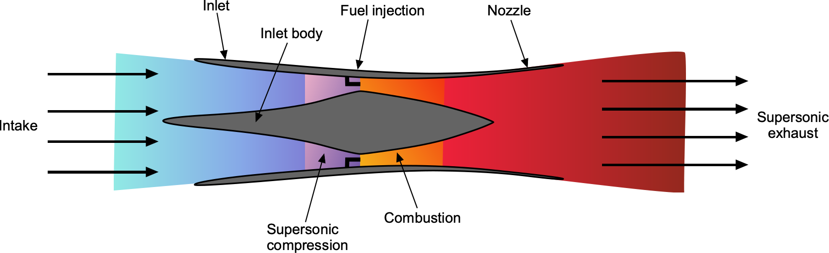
Scramjets offer the possibility of efficient, sustained propulsion in the Mach 5 to 10 regime. Their ability to operate without an onboard oxidizer and extract energy from atmospheric air makes them attractive for high-speed cruises and access-to-space missions. However, their dependence on high-speed entry, narrow operating envelope, and sensitivity to combustion stability and thermal limits remain open areas of research and development.
Combustion Process
The scramjet’s principle works on the Brayton cycle and relies on the vehicle’s forward motion compressing the incoming flow through a system of oblique and bow shocks. These shocks increase the air temperature and pressure to sufficient levels for combustion, even though the air remains moving at supersonic speeds inside the engine. Because of this, a scramjet cannot start or operate at low airspeeds; it requires the incoming air to be supersonic to ignite and sustain combustion. While it may operate inefficiently at lower Mach numbers, a scramjet typically requires acceleration to speeds near Mach 4 by another propulsion system, such as a rocket, turbojet, or ramjet.
Maintaining continuous combustion in supersonic flow is very challenging. The fuel-air mixture has an extremely short residence time in the combustor, typically just a few milliseconds, before it exits the engine. This short time makes it difficult to achieve efficient mixing and complete combustion. A rough estimate of the available combustion time is given by
(54) 
where is the length of the combustion chamber and  is the flow velocity, which remains supersonic. The challenge is further compounded by the formation of shock waves within the engine and complex shock-boundary layer interactions, which can lead to flow separation or instability that disrupts the combustion process. In addition, the high-speed flow produces severe aerodynamic heating, which requires the use of high-temperature materials and sometimes active cooling to manage the thermal loads on engine components.
Thrust Production
Momentum and pressure differences between the inlet and exhaust determine the thrust,  , that a scramjet produces. A simplified thrust expression based on a control volume momentum balance is
(55) 
where  is the incoming air mass flow rate,
  is the exhaust mass flow rate, is the freestream velocity,
  is the exhaust velocity,
  and are the exhaust and ambient pressures, and
  is the nozzle exit area. The fuel mass flow rate is denoted
  , so the total exhaust mass flow rate is
(56) 
In the ideal case of perfect expansion, the exit static pressure matches the ambient pressure ( ), eliminating the pressure thrust term and reducing the thrust equation to
(57) 
This form indicates that thrust arises from the momentum gained by both the incoming air and the injected fuel. The added fuel mass, although small compared to the air mass, carries significant chemical energy, allowing the exhaust velocity to exceed the freestream velocity . For good engine performance, the nozzle must be designed to produce at cruise Mach number. If the nozzle is not expanded correctly, then is reduced, and a pressure mismatch develops at the exit, resulting in degraded thrust and efficiency.
Specific Impulse
Unlike a rocket, which carries its oxidizer, a scramjet pulls in atmospheric air for combustion, making it more efficient in terms of specific impulse at high speeds. The specific impulse, defined as thrust per unit weight flow rate of fuel, is given by
(58) 
where  is the standard gravitational acceleration. Because a scramjet does not carry oxidizer, the total mass flow through the engine is significantly greater than the fuel flow alone, allowing for more momentum exchange with the atmosphere and resulting in greater thrust per unit of fuel consumed. This leads to significantly higher
  values than rockets, particularly in the Mach 5 to 10 range. Consequently, scramjets offer improved propulsive efficiency in high-speed atmospheric flight, although they are limited to operation within the atmosphere and require careful inlet and combustion control to maintain stability.
Thermodynamics
From a thermodynamic standpoint, combustion in a scramjet can be modeled as a high-speed, nearly constant-pressure process, similar to Rayleigh flow. The simplified energy equation is
(59) 
where  is the stagnation enthalpy[4] of the incoming flow, and is the heat addition per unit mass from fuel combustion. The flow gains total enthalpy from the chemical energy of the fuel, but experiences stagnation pressure losses because of shock interactions and viscous effects.
Although this framework describes the energy transfer in the flow, the amount of heat that can be added is ultimately limited by the thermal and structural capacity of the engine materials. The high-speed flow within the scramjet generates intense aerodynamic heating, particularly in the combustor and inlet regions. Surface temperatures can exceed 1,500 K and may reach over 2,000 K, depending on the Mach number, altitude, and flight duration.
Material limits impose strong constraints on the maximum allowable wall temperature. Conventional aerospace alloys, such as titanium or nickel-based superalloys, are generally limited to about 1,000–1,200 oK. Advanced ceramics, ultra-high-temperature composites, and refractory metals can tolerate higher temperatures, but are often brittle, expensive, or difficult to fabricate. Techniques such as regenerative cooling, thermal barrier coatings, or ablative surfaces may be employed to prevent thermal failure.
The maximum surface temperature a structure can reach in an adiabatic, uncooling case is approximately given by the recovery temperature, i.e.,
(60) 
where is the freestream temperature, is the Mach number, and  is the recovery factor, typically about 1.0 for laminar flow and 0.89 for turbulent flow. If this temperature exceeds material tolerances, active or passive cooling is required. Ultimately, the amount of energy that can be safely injected into the flow is limited not just by fluid dynamic choking effects but also by the capacity of engine walls to withstand thermal loads. These material constraints tightly couple thermodynamic performance to structural survivability in scramjet engine design.
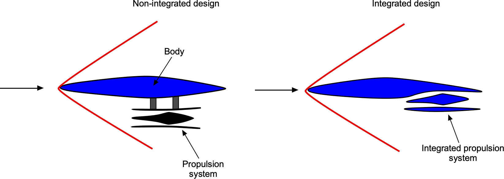
Airframe/Engine Integration
One feature of a hypersonic airplane is the need to carefully integrate all the parts of the aircraft that provide volume, such as for payload and fuel, with those for propulsion, like an engine or a scramjet. The figure below illustrates the basic concept of a “two-dimensional” configuration. An externally carried scramjet attached to the airframe (body) on a pylon would have an unacceptably high drag. However, properly integrating the body and the propulsion system could be expected to reduce wave drag on the body and a significant portion of the external nacelle drag. The penalties for this achievement include a slight loss of useful volume and the ingestion of some boundary layers on the body surface. Studies have shown that careful aircraft and propulsion design can be expected to increase maximum lift-to-drag ratios by approximately 1.5 times compared to a non-integrated design.
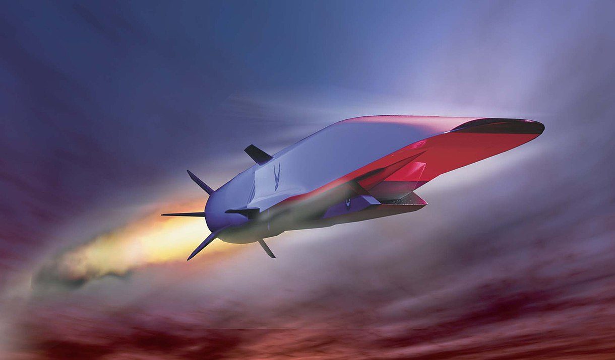
The Boeing X-51A scramjet demonstration aircraft was a waverider concept tested from 2011 to 2013, as shown in the artist’s impression below. The X-51A was used to demonstrate scramjet engine operations at hypersonic airspeeds and other aspects of hypersonic flight. The aircraft sustained Mach 5 flight for 200 seconds during its longest tests. Measurements made during these test flights have been compared with those made in hypersonic wind tunnels and predictions made using computational fluid dynamics (CFD).
Sonic Booms in Hypersonic Flight
In hypersonic flight, a critical acoustic phenomenon is the sonic boom. As a flight vehicle travels significantly faster than the speed of sound, it generates intense shock waves that coalesce into a sharply defined, cone-shaped disturbance trailing behind the vehicle. These waves propagate through the atmosphere and, upon reaching the ground, are perceived as a loud and sudden boom. In the hypersonic regime, the increased shock strength and wave compression result in more concentrated and potentially more damaging sonic boom signatures. The pressure rise across the shock is much steeper, and the resulting wave fronts are sharper and more nonlinear than those in lower supersonic regimes.
Quantitatively, the peak overpressure  of a sonic boom at ground level scales approximately linearly with the weight and with the square of the flight Mach number, i.e.,
(61) 
This relation indicates that a vehicle flying hypersonically at Mach 6 can produce a ground-level boom several times stronger than one flying at Mach 2, assuming similar geometry, weight, and altitude. The high energy associated with hypersonic shocks also reduces atmospheric attenuation, allowing the boom to propagate further at the ground.
Mitigating sonic boom intensity is a significant challenge in hypersonic vehicle design, especially for applications involving flight over land. Strategies to reduce boom intensity include increasing flight altitude, streamlining the vehicle’s planform and nose shape to distribute shock strengths more gradually, and employing “low-boom” design principles, such as boom shaping, which involves tailoring the vehicle’s volume distribution to produce a pressure signature that deviates from the classic N-wave. Continued research into sonic booms at hypersonic speeds is crucial for advancing high-speed flight, particularly in supporting future commercial, military, and space access vehicles that operate over populated areas.
Summary & Closure
Hypersonic flight vehicles operate in a regime where conventional aerodynamic assumptions no longer apply. At Mach numbers above 5, strong shock waves, high-temperature gas effects, and viscous-inviscid interactions dominate the flow field. The resulting kinetic heating can raise surface temperatures to thousands of degrees, imposing severe demands on materials and structural design. To withstand these conditions, hypersonic vehicles must incorporate specialized thermal protection systems and high-temperature materials, often involving ceramics, carbon-carbon composites, or ablative coatings. These constraints make thermal management a central aspect of vehicle design, tightly coupled to aerodynamic shaping and mission trajectory.
Propulsion remains one of the most challenging aspects of hypersonic flight. While scramjets (supersonic combustion ramjets) offer a promising solution for air-breathing propulsion in this regime, their operational stability, ignition, and integration with the airframe remain active areas of research. One of the most promising aerodynamic configurations is the waverider, which generates lift by aligning its lower surface with the shock wave it produces during flight. By effectively “riding” its own shock, the waverider minimizes wave drag while maximizing lift-to-drag ratio, offering improved efficiency at hypersonic speeds. The future of hypersonic flight will likely depend on continued advances in propulsion, high-temperature materials, and integrated vehicle design, culminating in systems capable of sustained, efficient, and potentially reusable high-speed atmospheric flight.
5-Question Self-Assessment Quickquiz
For Further Thought or Discussion
- What defines hypersonic speed, and why is it different from just “very fast”?
- Why does aerodynamic heating become a significant issue at hypersonic speeds?
- What kinds of shapes work best for hypersonic vehicles, and why?
- Why can’t regular jet engines work at hypersonic speeds?
- How do shock waves form, and why are they stronger at higher Mach numbers?
- What are some challenges in keeping a hypersonic vehicle stable in flight?
- Why do hypersonic vehicles fly high in the atmosphere?
- What kinds of materials are needed to survive the extreme heat of hypersonic flight?
- Why is testing hypersonic vehicles on the ground so difficult?
- How might hypersonic vehicles be used in the future, e.g., for space, military, or travel?
Other Useful Online Resources
For additional resources on hypersonic flight, follow up on some of these online resources:
- Hypersonic Waverider – How the USAF X-51A scramjet works – see the video here.
- Hypersonic Aerodynamics: Basic and Applied – start to watch the multi-part lecture here.
- 2025 AIAA Durand Lecture by Kevin Bowcutt – view the talk here.
- Testing and Analytical Challenges in Hypersonics – Dr. Mark Lewis – video available here.
- Hypersonic Flight Vehicle Design and Performance Analysis (AIAA short course) – see course info here.
- Hypersonic and High-Temperature Gas Dynamics by John D. Anderson – PDF available here.
- The Insane Engineering of Re-Entry – video available here.
- Entropy is a thermodynamic quantity that measures a system's disorder or randomness. ↵
- In aerodynamic flows, entropy increases when energy is degraded by shocks or viscous dissipation. ↵
- https://archive.org/details/nasa_techdoc_19930074866 ↵
- Enthalpy is a thermodynamic property that represents the total heat content of a system. ↵
