10 Aerospace Materials
Introduction
The evolution of aircraft materials is a significant aspect of aerospace engineering. Early airplanes were constructed from simple, wooden structures with glued-together parts and cotton fabric covering. While these designs could be constructed with basic tools, they lacked durability and required frequent maintenance. Advancements in construction materials and assembly processes led to the development of much more durable stressed-skin designs made of lightweight aluminum alloys. These alloys, which combine the base metal of aluminum with elements such as copper, magnesium, and zinc, have been the backbone of aircraft and spacecraft structures for nearly a century, underscoring the importance of material evolution in aerospace engineering.
Modern aerospace construction has witnessed a paradigm shift with the widespread use of composite materials. These materials, such as glass and carbon fiber-reinforced plastic composites, have become the cornerstone of streamlined aircraft and modern spacecraft. Their unique advantage lies in their ability to be shaped to efficiently carry applied loads, thereby reducing structural weight for a given strength and stiffness. This structural efficiency, often measured by the strength-to-weight ratio, has redefined the way we approach aerospace design and construction.
![\[ \frac{ \text{\small Material strength}}{\text{\small Structural weight}} \equiv \frac{\text{\small How strong the material is}}{\text{\small How heavy the structure is}} \equiv \text{\small Structural efficiency} \]](https://eaglepubs.erau.edu/app/uploads/quicklatex/quicklatex.com-65f800033b90da1feddceadef9e0a5b3_l3.svg "Rendered by QuickLaTeX.com")
However, other material properties, such as fatigue resistance, corrosion resistance, durability, and repairability, may also be essential considerations in selecting the most appropriate construction material(s) for a given aerospace application.
Learning Objectives
- Learn the factors involved in selecting materials for aerospace applications.
- Appreciate that different materials have different stiffnesses and failure levels.
- Recognize some of the advantages and disadvantages of composite materials for constructing aerospace structures.
- Discover emerging aerospace materials and production technologies, including 3D printing.
Types of Materials
When selecting materials for aerospace applications, several factors must be considered, including manufacturing methods and associated costs. Today, the choices often include using aluminum alloys, composites, or a combination of both. Sometimes, titanium alloys are used for their exceptional strength, toughness, and temperature tolerance (they do not creep), despite being at least five times more expensive than aluminum.
Each construction material has its own merits, and the choice depends on the aircraft’s specific requirements and mission. To keep the options open, it is usually advisable to leave the material selection for a “clean-sheet” airframe design quite broad. The table below compares the relative merits of different aerospace construction materials. Besides material strength, factors such as material costs, tooling, manufacturing processes, fatigue resistance, durability, repairability, corrosion resistance, and crashworthiness are also important. Please note that the rankings displayed in the table are somewhat subjective and based on a broad comparison; additional factors may also be considered beyond those listed in this table.
| Material | Cost | Tooling | Manufacturing Process | Fatigue Resistance | Durability | Repair-ability | Corrosion Resistance | Crash-worthiness |
|---|---|---|---|---|---|---|---|---|
| Wood and Fabric | Low | Low | Simple | Moderate | Low | Good | Low | Low |
| Stressed-Skin Aluminum | Moderate | Moderate | Moderate | Moderate | High | High | High | Moderate |
| Titanium | High | High | Moderate | Good | Good | Moderate | Good | Moderate |
| Modern Composites | High | High | Complex | High | High | Low | High | High |
- Wood and Fabric: This material was widely used in early aircraft because of its low cost and ease of construction. However, its lack of durability made it unsuitable for modern aircraft.
- Stressed-Skin Aluminum: Aluminum alloys have been widely used in aircraft construction since the 1930s. It was a significant improvement over wood and fabric, offering better strength and durability.
- Stressed-Skin Titanium: The use of titanium alloys in the airframe is attractive for high-speed flight vehicles because it offers the most balanced choice regarding strength, weight, and heat resistance. For example, the SR-71 Blackbird was primarily made of titanium, comprising over 90% of its structural weight.
- Modern Composites: Composite materials such as carbon fiber-reinforced polymers are widely used in contemporary aircraft because they are lightweight, highly fatigue-resistant, durable, and corrosion-resistant. They also offer excellent crashworthiness, especially when combined with Kevlar.
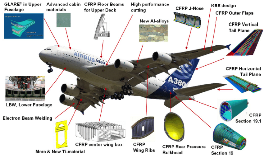
Modern aerospace structures may have 50% or more of their structure (by weight) made of various types of advanced composite materials, with some new airframe designs reaching as much as 90%. However, the material cost is high, and the tooling and manufacturing processes can be complex. The investments required for tooling in aerospace composite part manufacturing can be considerable. Airframe manufacturers typically outsource parts to companies specializing in the design and manufacture of parts made from one or more types of composite materials. As shown in the figure below, advanced materials can comprise a substantial proportion of the airframe and its weight.
How to make carbon fibers
Carbon fibers are produced by processing a precursor material, typically polyacrylonitrile (PAN), through several steps. The process begins with spinning the precursor into continuous fibers, followed by stabilization, where the fibers are chemically treated and heated in a controlled oxygen environment to align and cross-link carbon atoms. Next is carbonization, where the fibers are heated to extremely high temperatures (above 1,000°C) in an oxygen-free environment to remove non-carbon elements, leaving behind pure carbon. Then, the fibers undergo surface treatment to enhance bonding with resins and sizing, where a protective coating is applied to improve handling and compatibility with composite materials. These steps collectively produce the lightweight, strong carbon fibers for use in aerospace and other industries. However, production costs make carbon fiber materials considerably more expensive than metals like aluminum and steel.
Strength of Materials
The strength of materials is typically established by measuring coupons or other standard specimens using various testing methods. The tests used depend on the material characteristics that need to be established.
- Tensile Strength: Tensile strength tests measure the maximum stress a material can withstand while being stretched or pulled before it breaks. This stress is determined by placing a material sample in a machine that produces an axial tension and measures the strain until the sample fractures. The stress and strain at which failure occurs can then be determined.
- Compressive Strength: This measures the strength of the material when it is pushed or squeezed. The type of strength is determined by applying an inward force to a material sample until it fails.
- Shear Strength: This measures the material’s ability to withstand forces that cause the internal structure to deform under the action of parallel crosswise forces, i.e., the loading carried by a fastener such as a bolt or rivet.
- Flexural Strength: The flexural strength is determined by applying a bending moment to a sample until it fractures.
- Impact Strength: This measures a material’s ability to resist a sudden impact and how brittle it is. It is usually determined by subjecting a notched sample to a falling weight or pendulum and measuring the energy needed for the material to fracture.
These are just a few examples, and other specialized tests depend on the specific properties and applications of the material being evaluated. A material’s strength and other properties are crucial in engineering design to ensure that structures and components can withstand the loads and forces they will encounter during use, plus a margin of safety.
Young’s Modulus
The modulus of elasticity or Young’s modulus, which, as previously discussed, is given the symbol  , is one of the factors used to calculate a material’s “strength” and deformation under external loading, i.e., the higher the stiffness, the lower the deformation, i.e..
(1) 
Different materials have different values of and other characteristics, as shown in the figure below. Stiff materials have a higher Young’s modulus value but tend to be brittle, fracturing easily. Soft and easily extendable materials have a low value of Young’s modulus. There are many online resources where quantitative information on material characteristics is readily available. Notice that a stiff material has a high Young’s modulus and will change its shape only slightly under external loading. A stiff material requires high loads to deform it elastically. A flexible material has a low Young’s modulus, and its shape will change considerably under loading.
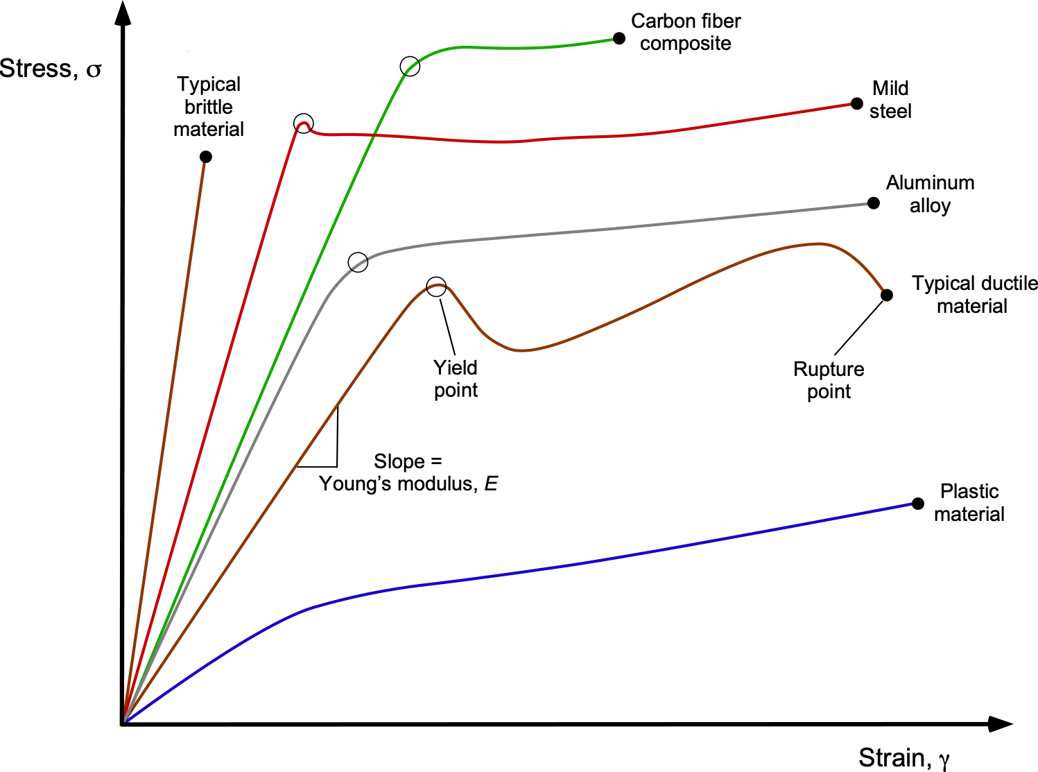
Eventually, as the applied load increases, the linear relationship between stress and strain changes and becomes nonlinear. This point is called the yield point, and the material now behaves more like a plastic (i.e., the material flows) in that deformations caused by the loads will remain even after the load is removed. Therefore, the material will take on permanent plastic deformation. Eventually, the material will break or rupture if the stresses become too high. A strong material requires high loads to permanently deform it as well as to break it.
The table below gives some reference values of Young’s modulus for aerospace materials. These values can vary slightly depending on the specific composition and treatment of the materials. Composite materials exhibit a range of values because of variations in fiber orientation, resin type, and fiber content. Graphene and carbon nanotubes are included because they represent the cutting edge of materials science, though they have yet to be commonly used in aerospace applications.
| Material | Young’s Modulus (GPa) | Yield Stress (MPa) |
|---|---|---|
| Aluminum Alloy (7075-T6) | 71.7 | 503 |
| Titanium Alloy (Ti-6Al-4V) | 113 | 880 |
| Stainless Steel (304) | 193 | 215 |
| Carbon Fiber Reinforced Polymer (CFRP) | 70–230 | 600–1,500 |
| Glass Fiber Reinforced Polymer (GFRP) | 70–90 | 500–700 |
| Inconel 718 | 200 | 1,035 |
| Beryllium | 287 | 240 |
| Magnesium Alloy (AZ31B) | 45 | 200 |
| Nickel Alloy (Hastelloy X) | 205 | 340 |
| High-Strength Steel (Maraging Steel) | 210 | 1,400 |
| Aluminum Lithium Alloy (Al-Li) | 79 | 470 |
| Graphene | ~ 1,000 | ~ 130,000 |
| Carbon Nanotubes (CNTs) | ~ 1,000 | ~ 40,000 |
| Wood (Sitka spruce) | ~9–13 | ~70–100 |
Materials Selection Charts
One approach to the material selection problem for an aerospace structure is to eliminate possible materials (e.g., wood, steel, etc.) rather than identifying the single best material too soon in the design process. Material selection charts are often used when choosing materials for a particular engineering application. In this type of presentation, one material property is plotted on the ordinate of the chart, and another property is plotted on the abscissa.
A particularly relevant material selection diagram for flight vehicle applications is one with strength on the ordinate and density on the abscissa, as shown below. In this case, the value of Young’s modulus describes how stiff the material is. This type of chart helps expose the relative benefits of particular materials, allowing for the selection of the most appropriate material for a specific structural application.
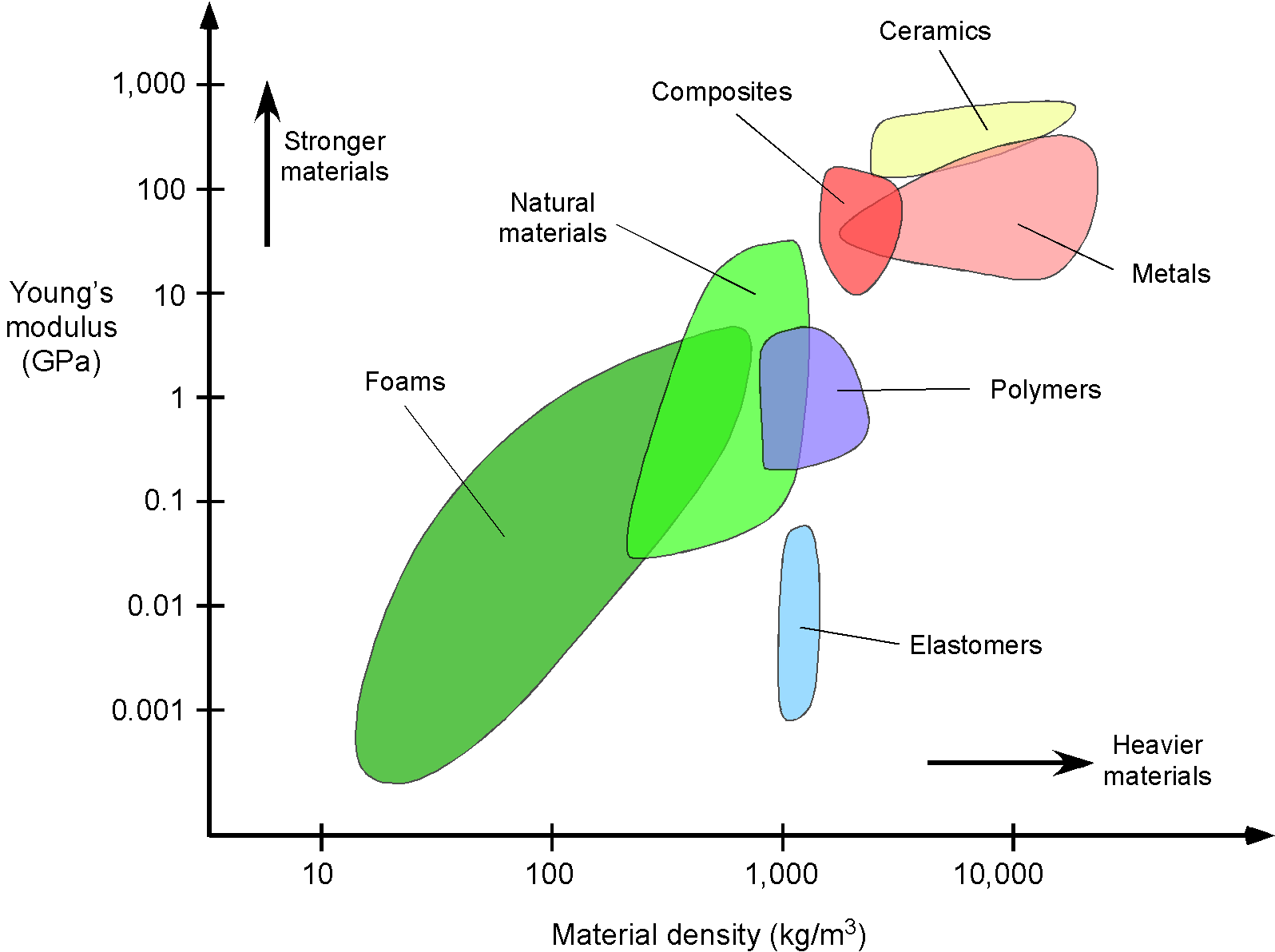
Regarding this type of chart, some materials appear very attractive for the lightweight, stiff components required for flight vehicles. Unfortunately, there are few inexpensive, strong materials. Wood is not strong enough to serve as a primary material for airframe construction, except for small airplanes. Three typical metallic construction materials for flight vehicle structures are aluminum, steel, and titanium. Steel is by far the heaviest, being approximately three times as heavy as aluminum or titanium, which rules it out as a primary construction material for most aerospace structures. However, steel is used for components that require significant strength and durability, such as landing gear. Aluminum alloys excel in terms of strength, lightness, durability, and cost, and have traditionally been used in the construction of aircraft. Although aluminum is lighter than titanium, titanium is stronger and has better fatigue resistance. Composites offer a good compromise, but they are usually relatively expensive, considering the material itself and the tooling required to manufacture the necessary components, such as molds, layup facilities, and autoclaves.
Check Your Understanding #1 – Material selection based on strength and cost
An aerospace engineer must choose between aluminum alloy 7075-T6 and titanium alloy 6Al-4V for machining a critical load-bearing component for a spar on an aircraft wing. The selection criteria include tensile strength, weight, and cost. The component must withstand a tensile load of 900 kN before reaching its yield point. Compare the relative features of the two materials to decide which one to use. Assume that the supplier can cut the material only into square blocks with linear dimensions to the nearest centimeter (cm).
The material properties and costs are:
-
-
- Aluminum alloy 7075-T6:
- Density: 2.81 g/cm

- Tensile Strength: 570 MPa
- Cost: $4 per kg
- Density: 2.81 g/cm
- Titanium alloy Ti-6Al-4V:
- Density: 4.43 g/cm
- Tensile Strength: 950 MPa
- Cost: $40 per kg
- Density: 4.43 g/cm
- Aluminum alloy 7075-T6:
-
Show solution/hide solution.
Consider first the aluminum alloy 7075-T6.
![\[ \text{\small Required cross-sectional area} = \frac{\text{\small Tensile load}}{\text{\small Tensile yield strength}} \]](https://eaglepubs.erau.edu/app/uploads/quicklatex/quicklatex.com-662ca6070d62f77216e88b54d034b954_l3.svg "Rendered by QuickLaTeX.com")
Therefore, the required area is
![\[ \text{\small Area} = \frac{900 \times 10^3}{570 \times 10^6 } = 0.001579~\text{m}^2 = 15.79~\text{ cm}^2 \]](https://eaglepubs.erau.edu/app/uploads/quicklatex/quicklatex.com-05fc0e79fded141ca170dc1530f8dd0b_l3.svg "Rendered by QuickLaTeX.com")
Therefore, rounding up to the nearest cm means that the volume of material required will be 256 cm, so the cost of the block at $4 per kilogram will be
![\[ \text{\small Cost} = 2.81 \times 256.0 \times (4.0 \times 10^{-3}) = \$2.88 \]](https://eaglepubs.erau.edu/app/uploads/quicklatex/quicklatex.com-79c5e0d725a85d65f7d59ac2d24cbe96_l3.svg "Rendered by QuickLaTeX.com")
Now, consider the titanium alloy Ti-6Al-4V.
![\[ \text{\small Area} = \frac{900,000}{950 \times 10^6} = 0.000947~\text{m}^2 = 9.47~\text{cm}^2 \]](https://eaglepubs.erau.edu/app/uploads/quicklatex/quicklatex.com-a2ccb7bcc0a87fe35548f25d6175db6a_l3.svg "Rendered by QuickLaTeX.com")
Therefore, rounding up to the nearest cm means that the volume of material required will be 100 cm, so the cost of the block at $40 per kilogram will be
![\[ \text{\small Cost} = 4.43 \times 100.0 \times (40.0 \times 10^{-3}) = \$17.72 \]](https://eaglepubs.erau.edu/app/uploads/quicklatex/quicklatex.com-d2ecda420d38d333eb89a8a526787195_l3.svg "Rendered by QuickLaTeX.com")
Notice also that the relative weight of the titanium alloy compared to the aluminum alloy will be
![\[ \dfrac{100.0 \times 4.43}{256.0 \times 2.81} \approx 0.62 \]](https://eaglepubs.erau.edu/app/uploads/quicklatex/quicklatex.com-b181e224c6623c19424dae205c90c6ca_l3.svg "Rendered by QuickLaTeX.com")
Conclusion: Titanium requires less material volume to carry the required load, resulting in a machined part that is smaller and approximately 40% lighter. However, making the same part out of titanium will be about six times the cost of materials alone. Titanium is also harder to machine, so it will take longer to make each part. The cost of making individual parts adds up quickly for serial production. If weight is a critical factor, then titanium may be the only viable choice. What would your choice be?
Composite Materials
Composite materials are increasingly important in the construction of aerospace structures. A composite material is defined as
(2) 
The matrix is usually a polymer or epoxy resin binder. The most common filler materials are glass and carbon fibers.
The advantages of using composite materials for structural design include their high strength-to-weight ratios, optimal load-carrying capabilities, reduced reliance on rivets and other fasteners, and enhanced fatigue and corrosion resistance. Eliminating rivets alone may result in a 5% reduction in structural weight compared to conventional aluminum construction methods. In the 1960s, secondary airframe structures, such as fairings, spoilers, and flight controls, were developed from composites to save weight compared to aluminum parts. New generations of aircraft are being designed with entire fuselages and wing structures made of advanced composites, although the manufacturing techniques and tooling require considerable financial investments.
The first type of aircraft to use a majority of composite materials was German sailplanes such as the Glasflügel Libelle. The RAH-66 Comanche helicopter was one of the first modern aircraft to use a high proportion of advanced composites in its construction. Advanced composites are typically classified as carbon fibers with fiber volumes greater than 50%, a characteristic now common in new airliners such as the Boeing 787 and the Airbus A350.
The aerospace industry continually strives to enhance airframe manufacturing by reducing weight and costs, and composite materials are highly attractive for this purpose. Modern composite airframe construction also enhances aerodynamics by eliminating surface joints and rivet heads, resulting in an exceptionally smooth wing shape that reduces drag. Today, larger, lighter, and more integrated aircraft and spacecraft structures are built from advanced composite materials.
Composite Construction
The construction of a composite structure involves a core fiber material embedded in a polymer or resin binder, commonly referred to as a polymer matrix. There are two main classes of advanced composites: thermoset and thermoplastic, but ceramic and metal matrix types also exist. Each of these substances alone has poor strength, but when combined appropriately in the matrix, they form a very stiff and strong structure. The fibers are the primary load-carrying elements of a composite material. Therefore, the material is only strong and stiff in the direction of the fibers, as shown in the figure below. Different combinations of fibers and orientations must be used to achieve the required properties of the composite material. Carbon fiber is the most common type of core material because of its high stiffness, strength, and low weight, and it is referred to as a carbon fiber-reinforced polymer (CFRP).
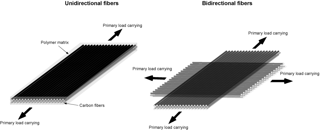
The fiber angles are critical, and the stacking sequence is crucial for achieving the optimal strength-to-weight ratio of the composite material. The fibers can be laid down and stacked in almost any combination of angles, ideally in an optimum arrangement to carry the applied loads most structurally efficiently. The stacking sequence and orientation of the fibers affect the composite material’s overall stiffness and failure strength. In a unidirectional composite material, the fibers are aligned in one particular direction and will only carry a load in that direction, as shown in the figure below. For the bidirectional orientation of the fibers, the mechanical properties will be distributed in both longitudinal and transverse directions. To carry loads in other directions, the layers can be configured at  45
45 or at any other angle needed to accommodate the imposed loads.
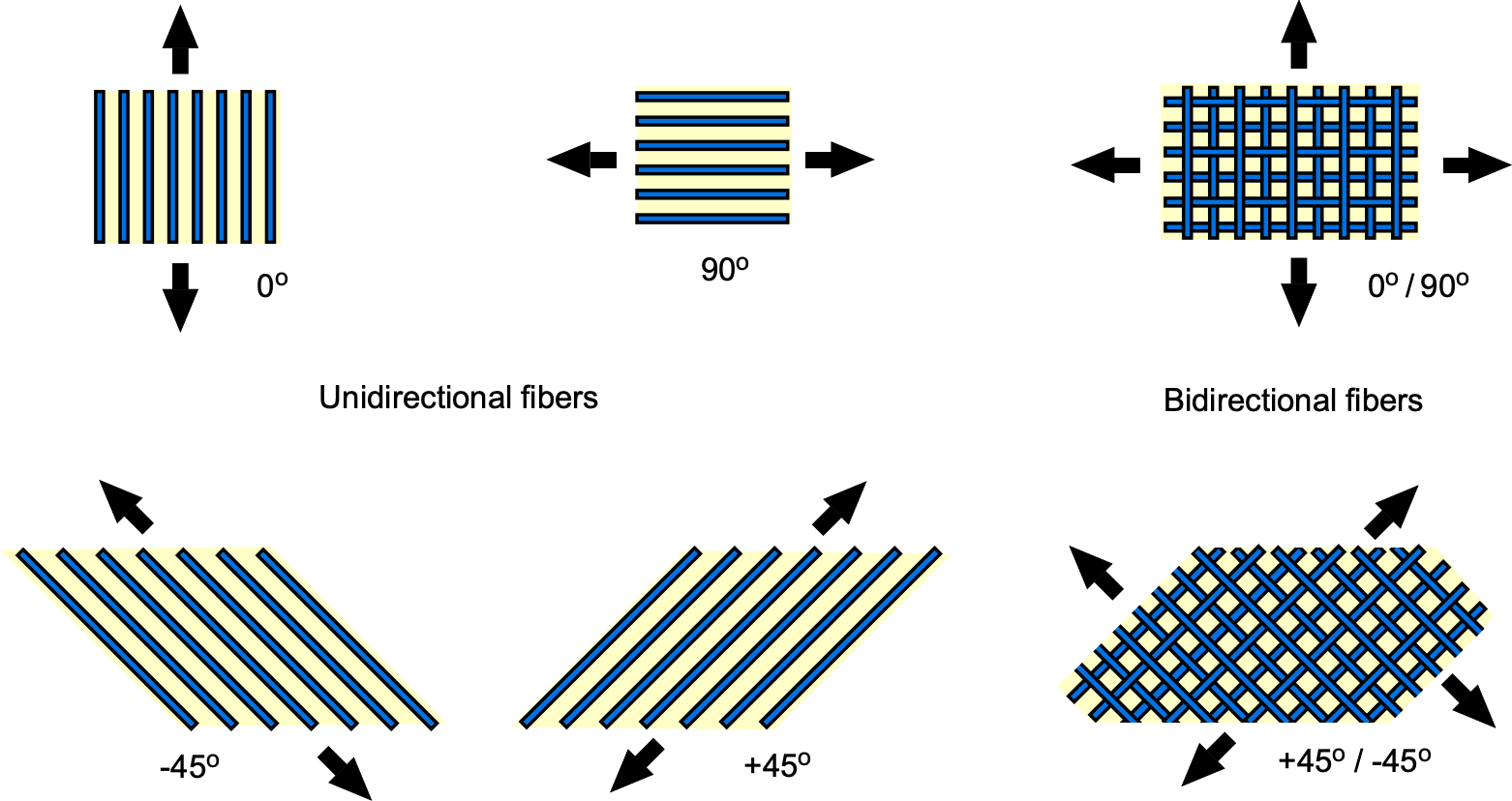
Airframe components made from composites can be designed using the Finite Element Method (FEM) to optimize the fiber orientations and stacking sequence, thereby producing the optimal mechanical properties of the component in response to applied loads. Making an anisotropic material (e.g., using combinations of bidirectional or multidirectional fibers) is critical to obtaining the high strength-to-weight ratio of composite components compared to using directionally isotropic materials such as aluminum.
Types of Fibers
The most common composite fiber reinforcement materials are glass, carbon and Kevlar. They are usually supplied as woven or knitted cloth. However, other forms are also used. Glass fiber (usually referred to as “Fiberglass” under its trademarked name) has good strength and stiffness, and is inexpensive and easy to work with. Often used for secondary structures, such as wingtips and fairings. Carbon fiber has excellent strength-to-weight and, more importantly, great stiffness-to-weight, which is very useful in primary structures. It is, however, much more expensive than glass fiber. Kevlar has good strength-to-weight but low stiffness. Therefore, because of its low modulus, it can more readily deform and absorb energy, which is beneficial for structures where crashworthiness is important. For example, airplane nose cones and wing leading edges are applications of Kevlar, which is less prone to fracture than carbon or glass fiber, even from a bird strike.
Types of Polymer Matrix Materials
There are many types of polymer matrix materials. i.e., plastics. Polyepoxides or epoxies comprise a bisphenol resin and a hardener that combine and cure to give a solid material. There are many different epoxy formulations with a wide variety of mechanical and other properties. Polyesters or vinyl-esters use a catalyst to cure them, although the catalyst itself is not chemically consumed. Polyesters and vinyl esters generally have poorer properties than epoxies and shorter working times, which makes them more challenging to use in specific manufacturing applications.
Material Properties
Composites typically exhibit high strength-to-weight ratios, making them ideal for applications where both high strength and low weight are crucial. The stiffness or rigidity of composites can be tailored by adjusting the type and orientation of the fibers. Every type of composite material can be uniquely different in terms of its stiffness and failure stress.
Stiffness
To estimate the stiffness or effective Young’s modulus for a composite material like CFRP, a method called the rule of mixtures is used. This stiffness value represents a weighted average of the individual stiffnesses of the materials comprising the composite. It considers the mechanical properties of the individual components (in this case, the fibers and the polymer matrix) weighted by their volume fractions in the composite.
The rule of mixtures for calculating the stiffness modulus of a composite material is given by
(3) 
where  is the Young’s modulus of the composite material,
  and
and  are the volume fractions of the fibers and matrix, respectively, and
  and
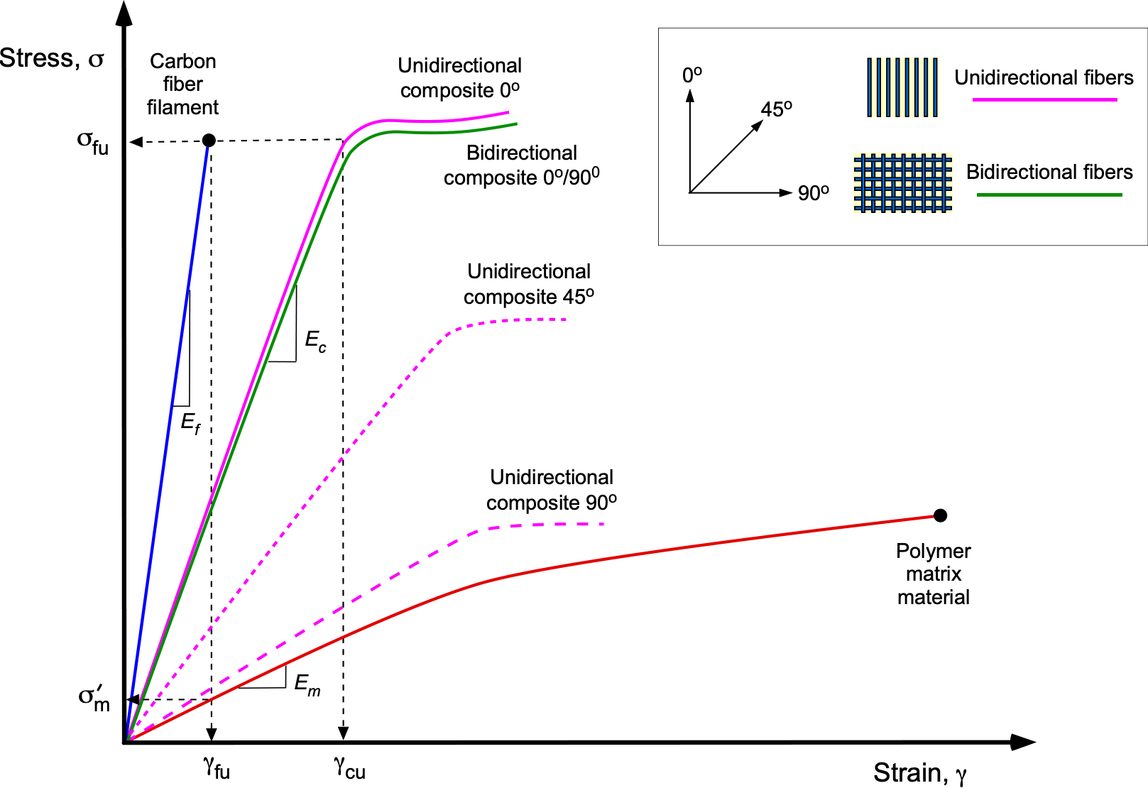
and  are the Young’s moduli of the fibers and matrix, respectively. This value is known as the upper bound stiffness modulus. It corresponds to the loading applied in a direction parallel to the fibers, which is the primary direction of load-carrying. Typically,
  , so the stiffness of the unidirectional composite is primarily determined by the stiffness of the fibers, as shown in the figure below. Bidirectional and multidirectional fiber orientations can carry loads in multiple directions, allowing the fibers to be arranged accordingly for a given loading application.
Notice that Eq. 3 can also be written as
(4) 
where the volume fraction of the fibers is
(5) 
The inverse rule of mixtures states that in the direction perpendicular to the fibers, the stiffness modulus of a composite is
(6) 
This latter value is referred to as the lower-bound stiffness modulus and corresponds to a case of transverse loading applied to the composite material, as illustrated in the figure. The validity of Eqs. 3 and 6 are generally limited to composites with fiber volume fractions of no less than 70%.
Maximum Stress Capability
The law of mixtures can again be used to determine a composite material’s strength or failure stress  . In this case, then
(7) 
where  and
and  are the ultimate (failing) stresses of the fibers and the matrix, respectively. Because
  , the ultimate strength of the composite is primarily determined by the strength of the fibers. However, the matrix increases the strain at which the fibers will fail.
Indeed, the figure above shows that the fibers will fail at a strain significantly less than what the plastic matrix can sustain, which is denoted by  , and so Eq. 7 will overestimate the ultimate stress. Therefore,
  can be replaced by , which is the stress in the matrix in which the fibers will fail. Therefore, instead of using Eq. 7 for the strength of the composite, it can be replaced by
(8) 
which will give a more reasonable estimate of the failure stress of a composite material. Normal production variations in the mechanical properties of the fibers and the matrix material(s) suggest that the calculated values are approximately 20% higher than those achieved through statistical testing.
Check Your Understanding #2 – Estimating the stiffness of a composite material
Given that the individual value of Young’s modulus of carbon fiber is 300 GPa, and for the matrix material, it is 3 GPa, determine the upper and lower bound moduli of a composite material where the volume fraction of the fibers is 70%. The volume fraction of the matrix is 30%.
Show solution/hide solution.
Using the rule of mixtures for calculating Young’s modulus of a composite material, where the loading is applied parallel to the fibers, gives
![\[ E_c = V_{\rm f } \, E_{\rm f } + V_{\rm m}\, E_{\rm m} \]](https://eaglepubs.erau.edu/app/uploads/quicklatex/quicklatex.com-f2c3ffdf5ef253c85161ec4963696817_l3.svg "Rendered by QuickLaTeX.com")
In this case, the modulus of the composite material will be
![\[ E_{\rm c} = 0.70 \times 300.0 + 0.30 \times 3.0 = 210.9~\mbox{GPa} \]](https://eaglepubs.erau.edu/app/uploads/quicklatex/quicklatex.com-efe39d63c8df8a746e47efac45e0bac4_l3.svg "Rendered by QuickLaTeX.com")
The fiber volume fraction is
![\[ f = \dfrac{V_{\rm f}}{V_{\rm f} + V_{\rm m}} = \dfrac{0.70}{0.70 + 0.3} = 0.7 \]](https://eaglepubs.erau.edu/app/uploads/quicklatex/quicklatex.com-a261bd1d6ef242dca9a802ec27fb1cc5_l3.svg "Rendered by QuickLaTeX.com")
Therefore, in the direction transverse to the fibers, the inverse rule of mixtures gives the modulus as
![\[ E_c = \left( \dfrac{f}{E_{\rm f}} + \dfrac{( 1 - f)}{E_{\rm m}} \right)^{-1} = \left( \dfrac{0.70}{300.0} + \dfrac{0.3}{3.0} \right)^{-1} = 9.76~\mbox{GPa} \]](https://eaglepubs.erau.edu/app/uploads/quicklatex/quicklatex.com-45a81b3f621d0ad280836b0405698868_l3.svg "Rendered by QuickLaTeX.com")
Manufacturing Processes
The manufacturing processes for composite materials include hand lay-up, automated fiber placement (AFP), out-of-autoclave (OOA) methods such as resin transfer molding (RTM), vacuum bagging, filament winding, pultrusion, and additive manufacturing (3D printing). Hand lay-up is a traditional, manual method suitable for flexible designs; however, it is labor-intensive, inconsistent in quality, wasteful of resources, and unsuitable for mass production. AFP utilizes robotic systems for precise and repeatable fiber placement, making it ideal for complex shapes, though it requires a significant initial investment in tooling. RTM involves injecting resin into a mold containing dry fiber preforms, offering good surface finishes and suitability for large, complex parts, albeit at the cost of high tooling expenses.
Vacuum bagging improves fiber-to-resin ratios and uniformity by compacting fiber lay-ups under a vacuum and is particularly useful for “one-off” parts. In contrast, filament winding is perfect for creating high-strength cylindrical structures by winding fibers around a rotating mandrel. Pultrusion is an efficient method for producing continuous, high-quality composite profiles with a constant cross-section, making it ideal for mass production. On the other hand, Out-of-Autoclave (OOA) processes, such as vacuum-assisted resin transfer molding (VARTM) and resin infusion, allow for the curing of composites without the need for high-pressure autoclaves. These methods significantly reduce manufacturing costs, particularly for large structures such as wind turbine blades or aerospace components. However, OOA composites typically exhibit slightly lower mechanical properties and strength-to-weight ratios than their autoclave-cured counterparts, because of differences in fiber consolidation and void content. Additive manufacturing, also known as 3D printing, is rapidly emerging in composite materials (e.g., carbon-impregnated) for rapid prototyping and the creation of complex designs. However, it currently offers lower strength and less predictable manufacturing consistency.
These advanced manufacturing techniques are becoming increasingly crucial in the aerospace industry. They are used to produce components such as fuselage sections and interior parts, where high strength-to-weight ratios, corrosion resistance, and fatigue resistance are crucial. The choice of manufacturing process depends on factors such as part complexity, production volume, and specific performance requirements. By enabling the creation of high-performance composite materials, they continue to reduce weight and improve overall structural efficiency in aerospace applications.
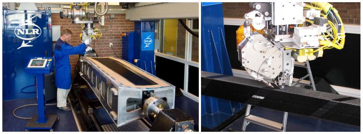
The photograph below shows a carbon-fiber composite wing spar laid up for autoclave curing. The fibers are laid down in a mold as a tape impregnated with uncured resin; this material is often referred to as “prepreg.” Prepreg composite materials can be arranged anisotropically, with the fibers best aligned at the angles needed to carry the applied bending, shear, and torsional loads. The resulting layup is cured under pressure and temperature in an autoclave to produce the final structure. The manufacturing processes are designed to create high-quality composite parts that meet the standards required for the airworthiness certification of aerospace products.
Concerns with Composites
One concern in the manufacture of composite materials is the predictability and repeatability of their properties, which will influence the material constituents, manufacturing processes, and the accuracy of modeling techniques. While advanced manufacturing methods and sophisticated simulations have significantly improved predictability, ongoing testing and validation are crucial to ensure that the composites meet the desired performance criteria in practical applications. Mechanical testing (tensile, compressive, and shear tests) and non-destructive testing (ultrasonic and X-ray) confirm the predicted performance and identify any discrepancies.
Another concern for aircraft made of composite materials is the detection and repair of damage. While damage in metallic structures may be relatively easy to detect (e.g., a visible surface dent or a crack), damage in composite parts is often subsurface, such as delamination or internal fiber cracking. Therefore, it may be difficult to tell visually that the part is damaged, especially if access to visual inspection is limited.
Composites can also be more difficult to repair after damage than metallic construction. With a metallic structure, the damaged area or part can often be cut out and a new part riveted in. However, if damaged composites need to be patched, a new structure must be layered into the old structure and bonded in place. New repair methods are constantly being developed for composite materials that restore the structure’s original design strength. Nevertheless, composite structural repair requires specialized tools and materials and must often be accomplished at specialized repair facilities, which are only available at some airports. In this regard, damaged aircraft may need to be ferried to specialized facilities, where the damage is repaired and the airplane is returned to service.
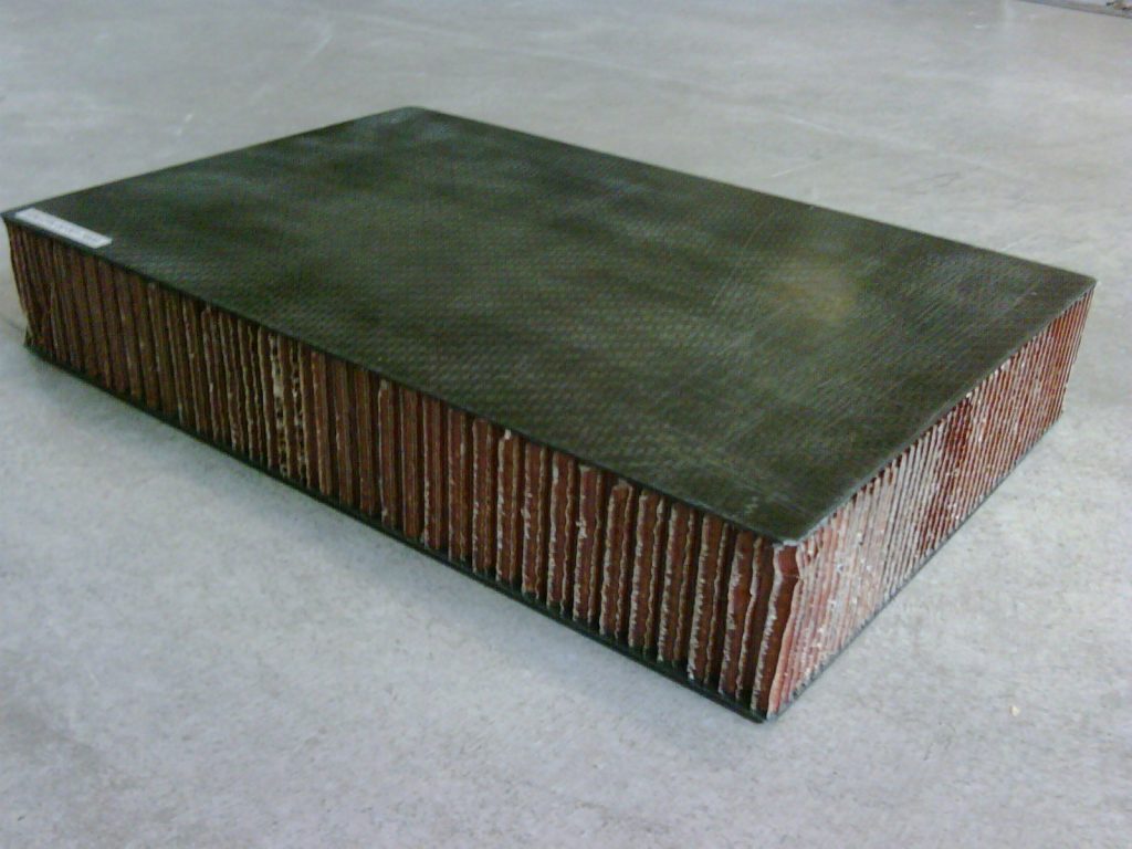
Sandwich Materials
A sandwich structure is built from a lightweight core material laminated or sandwiched between thin outer skin sheets using an adhesive, as shown in the photograph below. The paper honeycomb material is called Nomex, but aluminum honeycomb or foam like Rohacell may also be used. The skins may be made of aluminum sheets or composite materials. In some high-temperature applications, stainless steel could be used.
Material Fatigue
Fatigue is a material failure that results from repetitive loading cycles, typically at high applied stress levels. In a fatigue failure, a structural component will fail at an applied load that is significantly below the average failure load. Aluminum airframe structures are prone to fatigue issues because they are highly stressed and subjected to repetitive loading cycles, such as during takeoff, routine flight, maneuvering, rough air, and landing. Composite materials tend to have much better fatigue characteristics. Although wood is rarely used today for the construction of airplanes, other than for homebuilts, it has fairly good fatigue characteristics. Regardless, sharp corners and regions of stress concentration are always potential sources of fatigue cracks, so round holes and smooth transitions are used to increase fatigue resistance. Assessing the fatigue life of an airplane under long-term cyclic loading is an integral part of the design process.
Metal Fatigue
Metal fatigue is the weakening of a metal caused by repeatedly applied cyclic loads, typical of those found in flight structures, resulting in the formation of cracks.[1] The tragic crashes of the de Havilland Comet brought attention to the issue of metal fatigue, which was found to have originated at stress concentrations at improperly prepared rivet holes. The pressurized fuselage, combined with the thin skin and higher stresses around window cutouts, led to the Comet’s fuselage suffering explosive decompression, resulting in the loss of two aircraft. The original report explains the details. The subsequent research and understanding of the metal fatigue problem led to significant improvements in the strength and durability of lightweight aluminum structures that benefited all airframe manufacturers.
The mechanism of metal fatigue begins with the development of small microcracks within the structure. These grow slowly over many repeated loading cycles to become notable cracks, until eventually, the surrounding material catastrophically fails from local overstress, as shown in the schematic below. Such cracks often occur in areas of highly loaded airframe structures but are usually difficult to inspect, at least using visual methods. As a result, they can go unnoticed until structural failure occurs, posing a safety-of-flight issue.
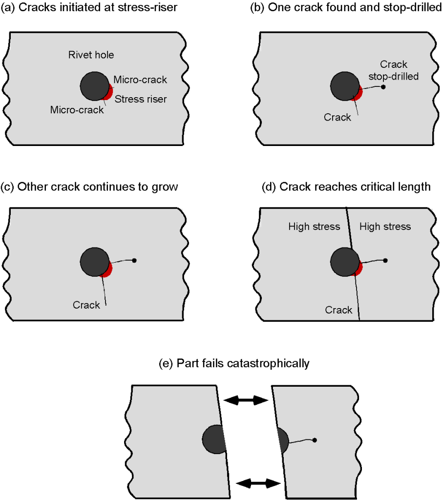
Fatigue failures generally occur in localized regions called stress risers, which can be caused by damage, scratches, or corrosion. Rivet holes are a common source of fatigue cracks, and they must be adequately prepared after careful drilling to remove any burrs and rough edges before driving a rivet home. After many loading cycles, micro-cracks can be initiated in the metal at any stress riser. These cracks grow in size and length with each loading cycle, although the initial process is typically prolonged.
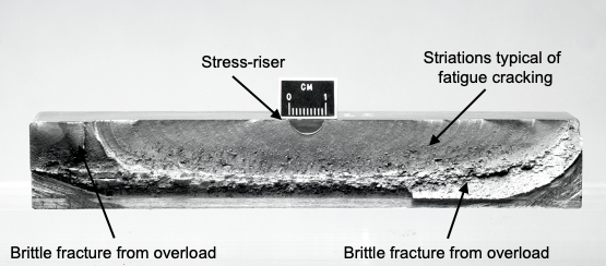
Eventually, the enlarged cracks can reach a size where the stresses at the tip are high enough to cause more rapid crack propagation. The signature of crack growth in the material is the curved striations emanating radially from the stress riser, as shown in the photograph below. The higher stresses acting over the remainder of the (uncracked) material become sufficient to cause sudden ductile failure from stress overload. However, it may take tens or hundreds of thousands of loading cycles for this process to occur, assuming the cracked part is not noticed during routine inspection and then repaired or replaced.
Fatigue characteristics are measured by testing material coupons, sub-structures, and even complete airframes. By subjecting the structure to the simulated cyclic magnitudes and stress levels encountered during flight, areas prone to fatigue cracking can be identified and remedied. Remediation includes replacing the part or reinforcing the structure with a patch or a doubler. The importance of FEM at the design stage cannot be overstated, as it can predict areas of locally high stresses and those likely to be subjected to fatigue issues before the structure is even built.
Despite best design practices to eliminate stress risers, fatigue cracks will inevitably appear in an aircraft structure over decades of use, e.g., especially on so-called aging aircraft. Therefore, detecting and repairing such fatigue cracks is crucial to prevent them from leading to severe structural failure. In simple, unpressurized structures, the crack growth can be stopped by drilling a suitably radiused hole at the end of the crack to relieve the stresses. In pressurized structures, a complete repair may be required by adding an appropriately sealed reinforcing structure. Aging aircraft may also suffer from corrosion issues and corrosion-induced fatigue cracking, resulting in serious structural problems that may be difficult and expensive to repair. For these reasons, older aircraft are often retired from service when they experience significant downtime and/or costly repairs.
Wöhler Curves
The fatigue properties of materials are often described using an  –
– curve or Wöhler (Woehler) curve, an example being shown in the figure below. The – curve describes the relationship between cyclic stress amplitude and the number of cycles to failure. On the abscissa, the number of cycles to failure is given on a logarithmic scale, and on the ordinate (either linear or logarithmic), the cycle’s stress amplitude (or sometimes the maximum stress) is used.
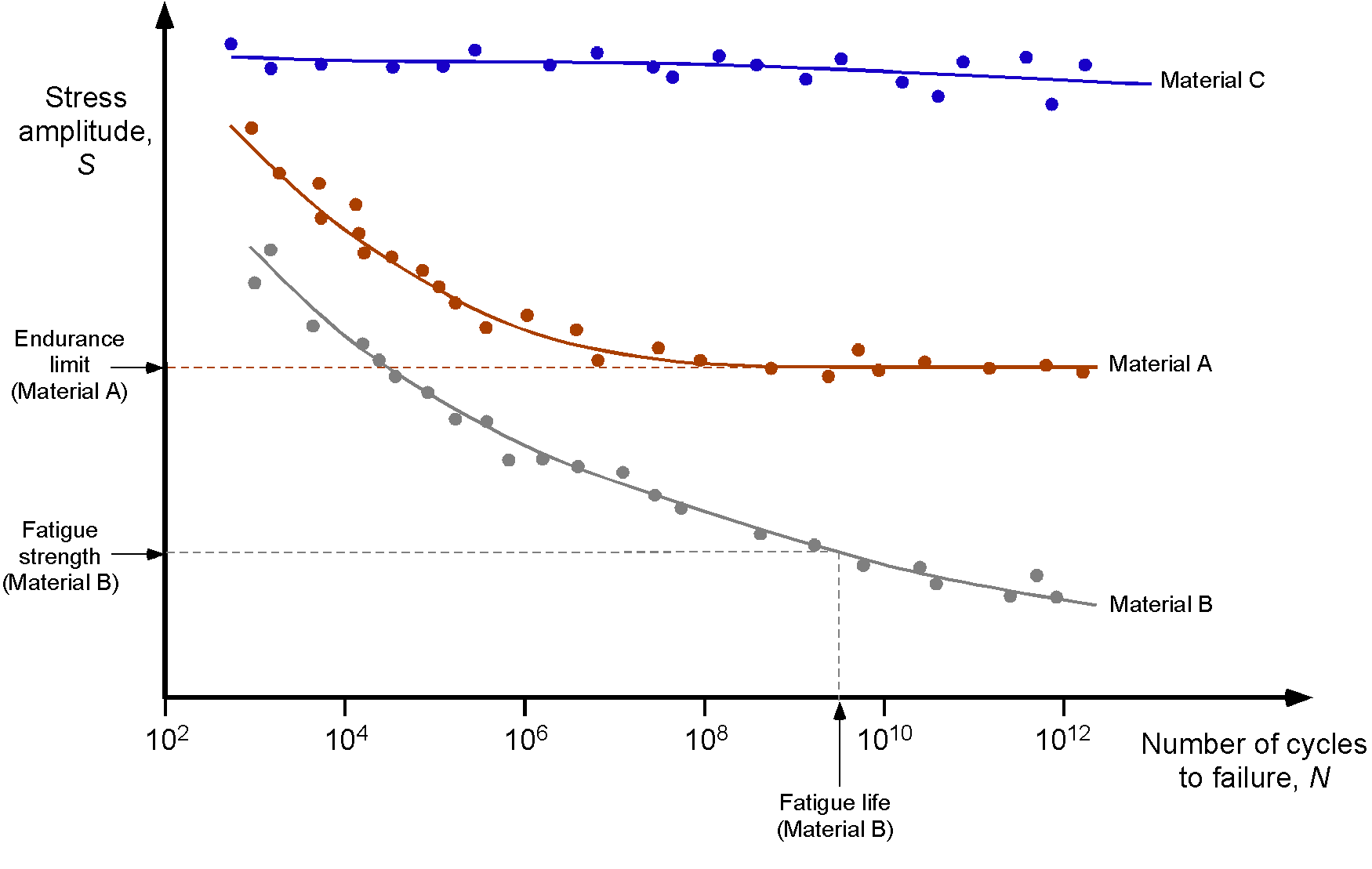
Ferrous materials, typical of Material A, tend to have good fatigue properties. They generally exhibit an endurance limit below a certain stress amplitude, effectively having infinite fatigue life. Aluminum, typical of Material B, does not exhibit this behavior and will continue to show decreasing fatigue resistance with increased cycles. In most cases, aluminum parts subjected to high cyclic stresses must be assigned a safe life, meaning that the part must be withdrawn from service after a certain number of cycles are reached, often measured in takeoffs and landings or flight hours. Composite materials, typical of Material C, have good fatigue properties and are much better than most metals. However, their fatigue characteristics tend to exhibit significant variability during testing, despite generally exhibiting excellent properties and having significantly longer fatigue lives than aluminum.
These types of – curves are obtained from fatigue tests conducted under controlled laboratory conditions. Tests are performed by applying cyclic stresses with a constant stress amplitude to various specimen types until final fatigue failure occurs. Sometimes, testing may be stopped after many cycles ( ), with the results being interpreted as indicating an infinite service life. Fatigue curves are often obtained for material specimen coupons, which are designed to represent the fatigue properties of the material itself rather than a specific part.
Actual flight structures of multiple components will have more specific – curves. Sometimes, a critical flight structure being tested, such as a wing spar or wing carry-through structure, will have notches cut to initiate fatigue cracking so that the fatigue life of the aircraft is not overestimated. Complete airframes may also be tested on the ground in a test rig, where cyclic flight loads can be simulated more quickly, allowing potential issues to be identified before the aircraft develops fatigue cracks in regular use.
How does wood compare to aluminum for an airplane structure?
Aluminum outperforms wood in terms of tensile strength; however, the choice between the two depends on the specific application. Newly cut wood has a tensile strength ranging from 40 to 140 MPa, depending on species and grain direction. In contrast, aluminum alloys are at least twice as strong, achieving isotropic tensile strengths ranging from 300 to 570 MPa, and provide more uniform and predictable performance. Aluminum lacks a clear fatigue limit and will eventually fail under repeated stress. Woods, like pine and spruce, will suffer from fatigue, but they have a higher endurance limit than aluminum. The cyclic longevity of wood used in an airplane structure depends more on its age, as the moisture content changes and the cellular structure begins to deteriorate. Aluminum is consistently the preferred choice for aircraft applications that require structural load-bearing capacity and long-term durability.
Miner’s Rule
An aircraft will be subjected to many types and amplitudes of stress during normal flight. Unexpected loads, such as the occasional hard landing, may have to be factored into the fatigue life estimate. It is possible to estimate the fatigue life using the method known as Miner’s Rule. This rule states that the cumulative fatigue damage is given by
(9) 
where  is the number of load cycles to which the component has been subjected in a certain stress range, and
  is the number of load cycles in that stress range to reach fatigue failure. The index
  varies over
  discrete stress ranges. The ratio
  is referred to as the partial fatigue damage; among all partial damage cycles occurring across all stress ranges, it is then a measure of the total fatigue damage. Failure can be expected to occur when
  .
.
Miner’s Rule assesses the fraction of the fatigue life consumed at each stress level and then adds the fractions for all the levels to estimate the fatigue damage in aggregate. The stress level damage can be defined as the product of the stress,  , and the number of cycles, , operated under that stress, i.e.,
(10) 
Miner’s Rule assumes that the stress level damage to failure is the same for all applied stress levels, so
(11) 
For example, if  for a component, it will fail after 5,000 cycles at a stress level of 1, 1,000 cycles at a stress level of 5, or 2,500 cycles at a stress level of 2, etc. Therefore, the cumulative damage can be written as
(12) 
While Miner’s Rule is imperfect, partly because it assumes that the fatigue damage in each stress range is linearly additive, it gives reasonable estimates of structural fatigue life.
Check Your Understanding #3 – Estimating fatigue life
It is required to estimate the “cycles to failure” of a thin aluminum rod. Preliminary experiments suggest that the angle between the two arms of the bent rod affects the number of cycles to failure. Therefore, the “angle” can be treated as a surrogate for the “stress.” The first test suggests that it takes 63 repeated bends to an angle of 30 degrees for the rod to suffer a fatigue failure. A subsequent test on a new rod subjects it to the following repeated bends and loading cycles:
| Bend angle (deg) | Cycles |
|---|---|
| 15 | 40 |
| 40 | 15 |
| 45 | 10 |
Based on Miner’s rule, how many cycles with a 30-degree bend can be expected to break the rod?
Show solution/hide solution.
It is necessary to calculate the cumulative damage for each stress cycle, i.e.,
![\[ D = \frac{1}{W_{\rm fail}} \sum_{k = 1}^{K} n_k \, \sigma_k \]](https://eaglepubs.erau.edu/app/uploads/quicklatex/quicklatex.com-221a19c706b897fa0e839e60c6e273d4_l3.svg "Rendered by QuickLaTeX.com")
In this case,  , so the cumulative fatigue damage, in this case, can be expressed as
![\[ D = \frac{(15 \times 40) (30 \times 15) 45 \times 10) 30 \times N}{1,890} = 1 \]](https://eaglepubs.erau.edu/app/uploads/quicklatex/quicklatex.com-4234e2ba62b9d288fa5dd151e4a2946f_l3.svg "Rendered by QuickLaTeX.com")
where is the remaining number of cycles. Performing the arithmetic gives
![\[ D = \frac{600 \times 450 \times 450 \times 30 \times N}{1,890} = 1 \]](https://eaglepubs.erau.edu/app/uploads/quicklatex/quicklatex.com-169d00bdf4575303d7137f9a9b52aa95_l3.svg "Rendered by QuickLaTeX.com")
Therefore,  , and so
  .
.
Thermal Protection Materials
Thermal protection materials are essential for safeguarding spacecraft during the extreme conditions of atmospheric re-entry and deep space missions. These materials are designed to endure high thermal loads, ensuring the integrity and safety of the vehicle and its contents.
Ablative materials, like phenolic-impregnated carbon ablator (PICA) and SLA-561V, absorb and dissipate heat by eroding in a controlled manner, protecting the spacecraft from intense temperatures. Reinforced Carbon-Carbon (RCC) composites, used in critical areas such as the Space Shuttle’s leading edges, can withstand temperatures up to 1,650 °C. Like those used on the Space Shuttle, ceramic tiles and flexible insulation blankets, such as Advanced Flexible Reusable Surface Insulation (AFRSI), provide additional thermal protection layers through high-temperature resistance and lightweight, conformable insulation.
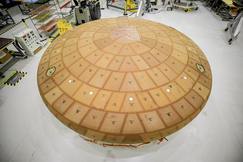
Each type of thermal protection material offers unique advantages suited to specific mission needs. For example, the Mars Science Laboratory’s Curiosity Rover utilized a PICA heat shield to withstand the heat of the Martian atmosphere’s entry. Multi-layer insulation (MLI), composed of reflective layers separated by spacers, is crucial for maintaining temperature control in the vacuum of space and is often used in satellites and other spacecraft. The Orion spacecraft employs an advanced AVCOAT system, as shown in the photograph below, which combines ablative properties with a honeycomb structure for enhanced performance. These materials and systems are fundamental to the success of space missions, providing the necessary protection against the harsh thermal environments encountered during launch, transit, and re-entry.
Additive Manufacturing & 3D Printing
Additive manufacturing, sometimes referred to as 3D printing, involves constructing a part directly from a computer-aided design (CAD) model. The basic principle is that an appropriate material is deposited, joined, and solidified, typically layer by layer, to make a part. Fused filament fabrication or fused deposition modeling is the most common method for making 3D-printed parts. This process uses a continuous filament of a thermoplastic material, which is melted at a printer nozzle and deposited on the part in incremental layers. Techniques such as direct metal laser sintering and direct metal laser melting can also produce 3D-printed metal parts.
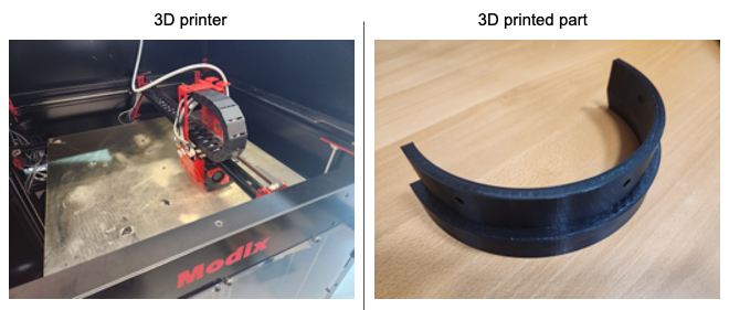
An advantage of 3D printing is the ability to produce complex shapes that would be difficult, time-consuming, and expensive to construct by conventional manufacturing methods. An advantage for aerospace applications is that 3D-printed parts can incorporate internal geodesic structures to reduce weight. The attractiveness of 3D printing technologies is such that the range of available materials has increased exponentially over the last decade. Some materials are now of the strength, surface finish, and overall quality that the industry uses for 3D printing production parts.
One of the concerns with 3D-printed parts for aircraft applications is ensuring their airworthiness, i.e., whether they can be safely used in flight. In the U.S., the FAA requires that all aircraft parts be manufactured to comply with airworthiness standards under FAA-approved production. To this end, aerospace manufacturers utilizing 3D printing will need to continue developing processes that comply with regulatory requirements and can demonstrate their airworthiness. Recently, the FAA approved the production of a 3D-printed fuel nozzle for the GE LEAP engine. This part was previously made from 20 welded pieces, but 3D printing technology allowed it to be manufactured from a single piece, reducing its weight by 25%.
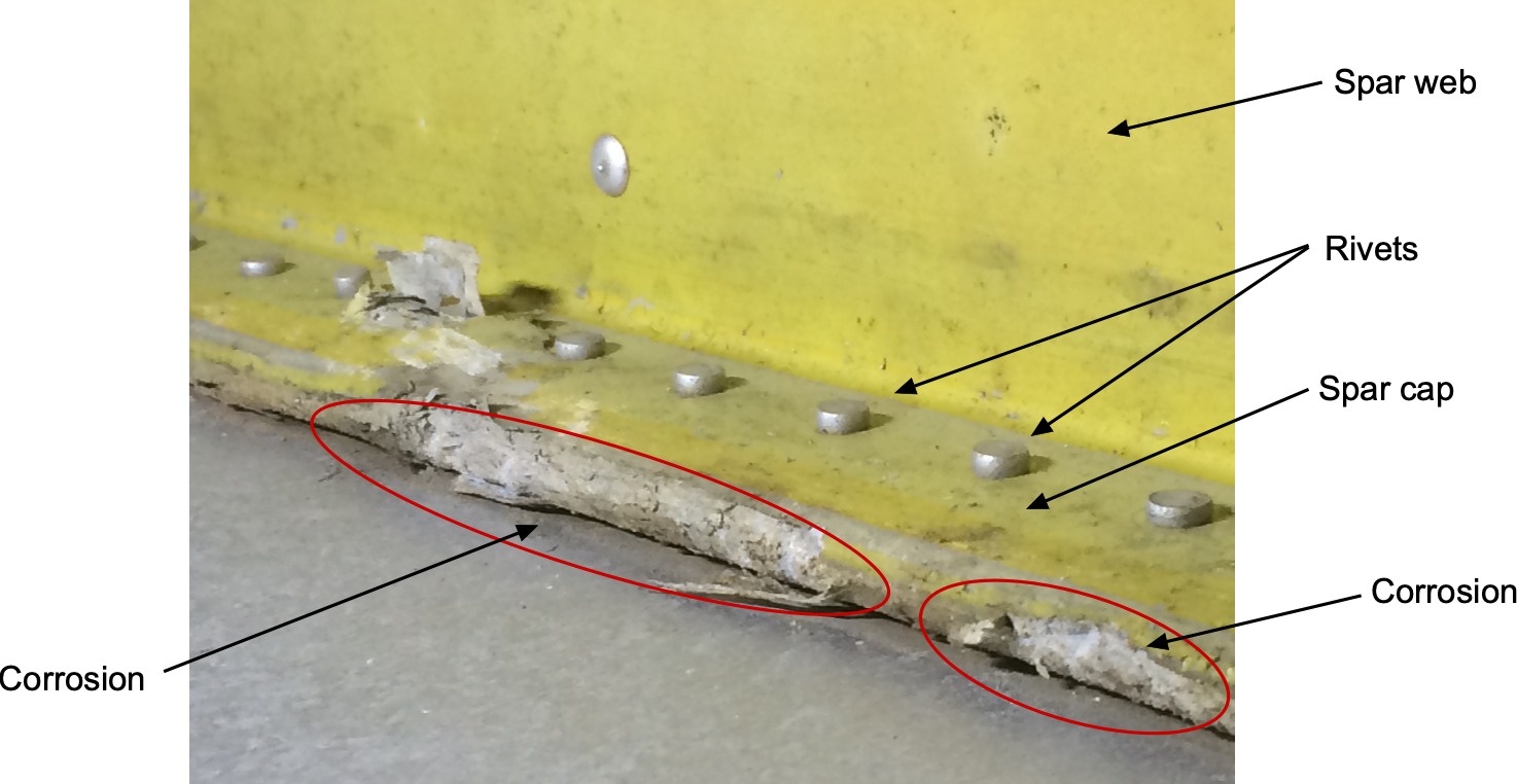
Corrosion of Materials
Airplanes are frequently exposed to humidity, salt-laden air, fuel and fuel vapors, de-icing fluids, and wide temperature variations. These conditions can accelerate various types of corrosion, a natural electrochemical process that degrades metals by returning them to their lower-energy oxide forms. Left unchecked, corrosion can compromise the structural integrity, performance, and safety of an aircraft. Consequently, material selection and protective treatments are critical elements of airframe design and maintenance. Airframe inspections for corrosion are a significant part of a regular maintenance program.
Corrosion in aircraft materials takes several forms, which include but are not limited to the following:
- Uniform corrosion affects large, exposed metal areas evenly and is typically the easiest to detect and treat.
- Galvanic corrosion arises when dissimilar metals are in electrical contact in the presence of an electrolyte (e.g., water), causing the more anodic material to corrode preferentially.
- Pitting corrosion appears as small, localized holes and is especially damaging to aluminum alloys.
- Crevice corrosion occurs in shielded areas where water may accumulate, such as under fasteners or in lap joints.
- Intergranular corrosion propagates along grain boundaries in susceptible alloys, particularly in improperly heat-treated aluminum or stainless steel.
- Exfoliation corrosion is a severe form of intergranular corrosion that occurs primarily in wrought aluminum alloys, especially those that have been rolled or extruded, leading to a flaking or delamination appearance.
- Stress-corrosion cracking (SCC) is the combined result of tensile stress and a corrosive environment, leading to sudden and often catastrophic failure.
Material Selection & Design Practices
Corrosion resistance is a crucial consideration when selecting materials for aircraft structures. Aluminum alloys are widely used because of their high strength-to-weight ratio, but they are susceptible to corrosion, especially in environments rich in chloride. Stainless steels, titanium alloys, and composites offer improved corrosion resistance, but are used selectively because of weight or cost constraints. Design strategies to mitigate corrosion include:
- Avoiding galvanic couples by separating dissimilar metals or insulating them with sealants or non-conductive coatings.
- Designing joints and drain paths to prevent moisture accumulation.
- Using corrosion-resistant fasteners and fittings.
- Minimizing crevices and sharp corners where water and other fluids can stagnate.
Protective Treatments
A variety of surface treatments and coatings are employed to protect aircraft materials from corrosion:
- Cladding involves bonding a thin layer of pure aluminum (Alclad) onto heat-treatable aluminum alloys to combine mechanical strength with improved corrosion resistance.
- Anodizing is a controlled electrochemical process that thickens the natural oxide layer on aluminum, improving corrosion resistance and paint adhesion. Type II sulfuric acid anodizing is common in aircraft applications.
- Alodine (also known as chemical conversion coating) provides a thin, conductive, corrosion-resistant layer on aluminum without significantly altering dimensions. It is often used as a base layer for paint.
- Painting and primers, such as epoxy or polyurethane systems, serve as physical barriers to environmental exposure. Zinc chromate primers were historically common, but newer low-toxicity alternatives are now used.
- Sealants are applied to lap joints, fasteners, and fuel tanks to prevent fluid ingress and crevice corrosion.
Corrosion in Composites
Unlike metals, composite materials do not experience corrosion in the traditional electrochemical sense, as they contain no free metal susceptible to oxidation. However, composites are still vulnerable to environmental degradation over time. Moisture absorption, ultraviolet radiation, thermal cycling, and chemical exposure can all damage the polymer matrix or weaken the bond between fibers and resin, leading to reduced structural integrity.
A specific concern arises when carbon fiber composites are used in conjunction with metals such as aluminum. Because carbon fibers are electrically conductive, they can form a galvanic couple with adjacent metal components in the presence of moisture, causing the metal to corrode. To mitigate this risk, insulating layers, sealants, or protective coatings are applied at composite-metal interfaces. The inspection and maintenance of composite structures primarily focus on detecting damage modes, such as delamination, matrix cracking, and moisture ingress, typically using various types of non-destructive testing techniques, including ultrasound. Although composites offer excellent resistance to conventional corrosion, their durability still depends on careful design, environmental protection, and regular monitoring.
Maintenance & Inspection
Corrosion control is an ongoing process in aviation. Aircraft undergo regular inspections, such as visual, ultrasonic, eddy current, or dye penetrant inspections, which can be specifically targeted at corrosion-prone areas, including lap joints, fastener rows, fuel tanks, and wheel wells. When corrosion is discovered during maintenance, it must be removed entirely using approved methods, often involving mechanical (abrasive pads, sanding), chemical (acid treatments), or media blasting. The cleaned surfaces are then treated with corrosion inhibitors, coated with primer, and resealed with protective finishes to prevent recurrence. Maintenance manuals provide detailed guidance on allowable damage limits, inspection intervals, and standard repair procedures to ensure continued structural integrity and flight safety.
Future Aerospace Materials
The aerospace industry is constantly evolving, with new materials and technologies being developed to improve vehicle performance, reduce weight, and enhance safety. These innovations are helping to push the boundaries in the constant quest for more efficient, durable, and capable aircraft and spacecraft. Future aerospace materials may include:
-
- Ceramic Matrix Composites (CMCs): These types of materials are known for their high-temperature resistance and low weight. Ceramics are increasingly used in jet engines and other components exposed to extreme heat, such as turbine blades, where they can operate at higher temperatures than traditional metal alloys, thereby improving engine efficiency and reducing fuel consumption.
- Graphene and Carbon Nanotubes: These nanomaterials offer extraordinary strength-to-weight ratios and electrical conductivity. Carbon nanotubes (CNTs) are manufactured cylindrical molecules composed of carbon atoms arranged in a hexagonal lattice, as shown in the figure below, which is similar to the structure of graphene. They come in various forms, including single-walled carbon nanotubes (SWCNTs) and multi-walled carbon nanotubes (MWCNTs), each with unique properties and applications. Their applications in aerospace include lightweight structural components, advanced sensors, and improved batteries.
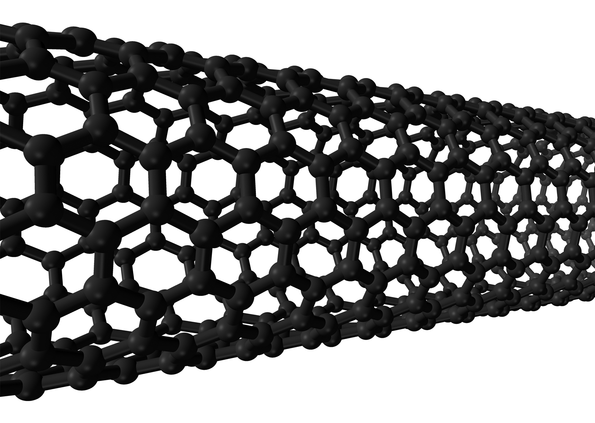
A single-walled carbon nanotube. - Self-Healing Materials: These materials can automatically repair damage, which is particularly valuable for maintaining the integrity of aerospace structures over time. Polymers embedded with microcapsules of healing agents or materials that respond to environmental changes (e.g., temperature, pressure) or physical damage, are being researched for potential use in aircraft skins and other structural components.
- Shape Memory Alloys (SMAs): Shape memory alloys are made from nickel and titanium, called nitinol. These materials change their shape when heated above a specific temperature, for example, by passing an electrical current through them. They then return to their original shape when cooled; this concept is illustrated in the figure below. This effect occurs because of a phase change in the metal’s molecular lattice structure. Notice that SMAs must be cooled below the transition temperature when heated, thereby exhibiting a hysteresis in their strain behavior. Therefore, when heated and cooled, such materials can extract energy, produce forces, and do work. SMAs can potentially be used in various aerospace applications, including actuators and adaptive structures.
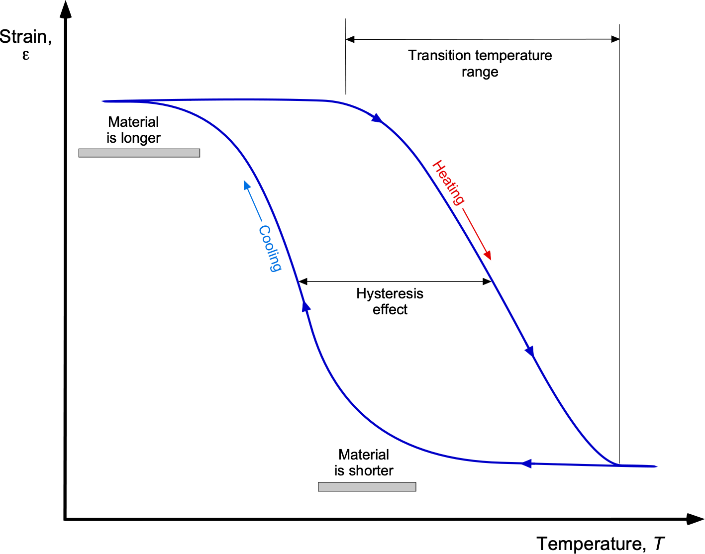
Shape memory alloys (SMAs) contract when the temperature is increased, and then they relax again when cooled. - Hybrid Materials: Combining different materials at the micro or nanoscale can result in hybrids with tailored properties for specific applications. For example, metal-polymer hybrids can offer the strength of metals with the lightweight properties of polymers.
- Multifunctional materials: Combining different materials can also allow them to be used for structural purposes, as well as, for example, having electrical conductivity. By using the structure to carry electrical power and signals, multifunctional materials could eliminate miles of wiring, and tons of weight could be potentially eliminated on a commercial airliner.
- Metamaterials: These are engineered materials with properties not found in naturally occurring substances. Metamaterials can manipulate electromagnetic waves, including light and radar. In aerospace, they are being explored for applications in stealth technology, antennas, and communication system improvements.
Summary & Closure
Aerospace structures are a key discipline in engineering, which is dedicated to designing and analyzing aircraft and spacecraft components. This discipline ensures that these structures are lightweight, durable, and capable of withstanding extreme conditions, such as high speeds, pressure differentials, and temperature variations. Utilizing advanced, lightweight materials and optimized structures is crucial for achieving lighter airframe components. The manufacturability of the structures from the selected materials is also essential because it affects the feasibility and costs of mass-producing the components. The development of advanced technologies, such as additive manufacturing, has the potential to further reduce airframe weight. For example, using 3D printing materials and techniques, complex structures can be created with minimal material waste, potentially yielding significant weight savings. As the aerospace industry continues to evolve, the ongoing advancements in structural materials and manufacturing technologies will play a pivotal role in shaping the future of air and space flight.
5-Question Self-Assessment Quickquiz
For Further Thought or Discussion
- Consider the expected costs of making airplane structures from molded composites versus traditional riveted metallic construction. Which method is likely to be more expensive, and why?
- Eliminating many fasteners in composite construction also improves fatigue resistance. Explain.
- What role do aerospace materials play in making the industry more sustainable? Discuss efforts to develop recyclable materials and reduce the environmental impact of material production and disposal.
- How do aerospace engineers address the challenges of material fatigue and durability? Discuss the importance of testing and modeling in predicting material behavior over the lifespan of an aircraft.
- What potential do nanomaterials have in the aerospace industry? Explore applications where nanomaterials can offer significant benefits and the challenges associated with their implementation.
- How are new materials being developed for space exploration, such as those used in the Mars rovers or the Artemis program? Discuss the specific requirements for materials used in space missions.
Other Useful Online Resources
To learn more about aerospace materials, try some of these online resources:
- Good video about the advantages of composite materials.
- NASA 360 Composite Materials AeClips.
- From Metals to Composites – Decoding aircraft materials.
- MAPTIS. An extensive database of materials properties and data used by NASA for aerospace applications.
- MatWeb. A comprehensive database of material properties, including many aerospace materials.
- ASM International offers a wide range of resources, including materials databases, handbooks, and journals focused on materials science and engineering.
- AZO Materials. Provides news, articles, and data on materials, including those used in aerospace applications.
- SAMPE. An organization dedicated to the promotion of technical excellence in materials and processes.
- ASTM International. Provides standards and technical papers on materials testing and specifications, including aerospace materials.
- CW CompositiesWorld. It focuses on composite materials, which are extensively used in aerospace applications.
- William Rankine was one of the first engineers to understand the phenomenon of metal fatigue. He demonstrated that the initiation and growth of brittle cracks led to the fatigue failures of railway axles. ↵
