67 Vertical Takeoff & Landing (VTOL) Aircraft
Introduction
Aircraft with vertical takeoff and landing (VTOL) capability can be realized in many ways, only one of which is the familiar helicopter. However, helicopters remain the most aerodynamically efficient form of vertical flight because their large, low-disk-loading rotors (i.e, their low thrust per unit of disk area) minimize the power required to hover and fly at low airspeeds. Engineers have nevertheless explored many other methods of generating vertical lift, mainly to integrate VTOL capability into fixed-wing aircraft that can cruise at much higher airspeeds than a helicopter can. These goals have produced a diverse range of non-helicopter VTOL and short takeoff and landing (STOL) concepts over the past eight decades.
The diversity of non-helicopter VTOL and STOL concepts is neatly illustrated by the V/STOL Wheel (of Misfortune), as shown in the figure below. This diagram catalogs decades of efforts to combine vertical takeoff with efficient wing-borne cruise. Initially developed by McDonnell Aircraft and later expanded by Michael Hirschberg, the Wheel serves as both a historical surve y and a reminder of how unforgiving the underlying physics can be. It also cautions engineers not to reinvent the wheel when selecting a configuration and reflects the many misfortunes encountered in advancing VTOL aviation.
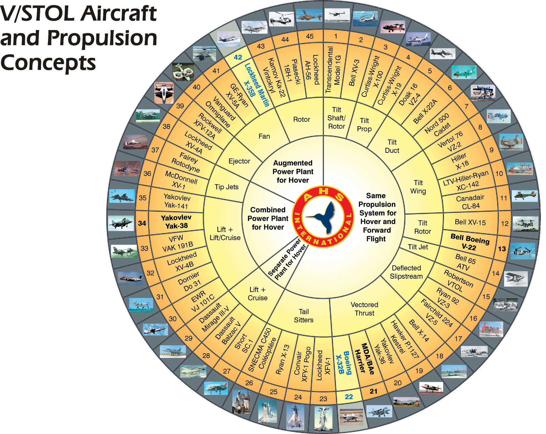
What unifies these VTOL aircraft is that vertical lift is produced by propulsion devices such as jet nozzles, highly loaded fans, or proprotors, rather than by large, low disk-loading helicopter rotors. These systems operate at conditions that significantly increase the power and fuel required per unit of flying weight compared to helicopters. Consequently, non-helicopter VTOL aircraft generally have limited hover endurance and restricted low-speed performance. Still, they may offer advantages in mechanical and structural simplicity, as well as more direct integration with high-speed fixed-wing configurations.
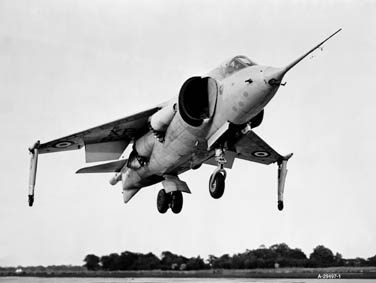
One VTOL aircraft that stands out in the Wheel is the Hawker P.1127 “Jump-jet,” which first flew in 1960, and became the McDonnell-Douglas AV-8B Harrier. It was the first practical aircraft to use a single vectored-thrust turbofan engine, the Rolls-Royce Pegasus, to provide all thrust required for takeoff, hover, transition, and forward flight, marking a significant advance in VTOL development. This integrated approach eliminated the weight penalty that plagued earlier lift-jet concepts, which often carried multiple vertical-lift engines that served no purpose in cruise. The P.1127 was also the first VTOL design to mature into an operational military fighter aircraft, evolving directly into the successful Harrier family and demonstrating that VTOL flight could indeed be achieved without sacrificing as much mission range, payload, or practicality to the extent seen in earlier VTOL designs.
It will become apparent that the engineering motivations for pursuing non-helicopter VTOL concepts are highly diverse, and each configuration reflects a different balance among hover efficiency, mechanical complexity, aerodynamic performance, and mission requirements. Jet-borne VTOL emphasizes compact, high-thrust platforms for demanding military operations, although efficiency is low and flight-control demands are high. Ducted-fan and blown-wing concepts explore ways to augment vertical lift or reduce the aircraft’s footprint while preserving acceptable aerodynamic performance. Tiltrotors and tiltwings seek to combine true vertical lift with the higher speed and range of efficient wing-borne cruise. Lift-plus-cruise and multirotor electric VTOL systems prioritize simplicity, redundancy, and good control authority, trading some aerodynamic efficiency for lighter structures and easier system integration.
This chapter examines these VTOL concepts within a reasonably unified framework. Rather than treating them as isolated inventions, the material emphasizes the shared physical principles governing vertical flight, the aerodynamic limitations, and the other requirements that differentiate each configuration. The discussion proceeds by configuration type, beginning with jet-borne VTOL and continuing through ducted-fan concepts, lift-plus-cruise architectures, tail-sitters, tiltrotors, and tiltwings. Helicopters are not included because they are covered comprehensively in another chapter of this eBook. The goal is to provide a coherent engineering foundation for understanding why so many VTOL concepts have been proposed, why relatively few have achieved operational success, and how modern electric propulsion concepts may now be reshaping the VTOL design space.
Learning Objectives
- Identify the major categories of VTOL concepts other than helicopters and explain the physical principles behind each.
- Describe the aerodynamic and other design features associated with tiltrotors, tiltwings, lift-plus-cruise designs, and ducted-fan systems.
- Be aware of the advantages and limitations specific to the various VTOL aircraft.
- Evaluate the trade-offs in performance between hover capability and forward flight across different configurations.
History
The pursuit of vertical flight beyond conventional helicopters has a long and varied history. Even before practical helicopters emerged in the 1930s and 1940s, engineers experimented with alternative ways to generate vertical lift by redirecting propulsive thrust or by mechanically tilting fixed wings and propellers. These early investigations and patents introduced many of the ideas that would later reappear in more mature VTOL concepts. From tilting propellers and tail-sitters to jet-borne VTOL fighters and today’s electrically powered VTOL concepts, the development of non-helicopter VTOL has followed recurring cycles of technological optimism, practical challenges, both technical and financial, and gradual progress. Each generation of VTOL aircraft designs has produced valuable insights, often through costly flight testing, into how vertical lift can be achieved and how to overcome the low-speed limitations of conventional helicopters.
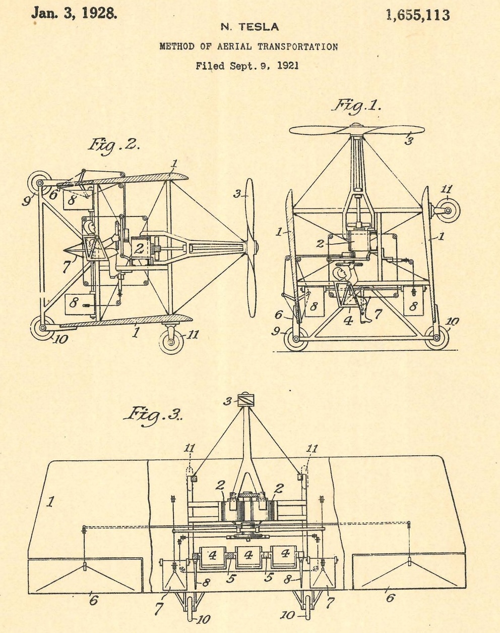
Early ideas for achieving vertical flight included several tilting-propeller concepts patented in the early twentieth century. One of the more imaginative examples was Nikola Tesla’s 1921 patent, which describes an aircraft in which a tractor propeller could be raised for vertical lift and then tilted forward to produce propulsion for wing-borne flight, as shown in the figure below. Although Tesla never built such a machine, the idea foreshadowed later tiltrotor and tiltwing aircraft by proposing a single propulsive system that could redirect thrust for vertical lift and then rotate forward for efficient wing-borne cruise.
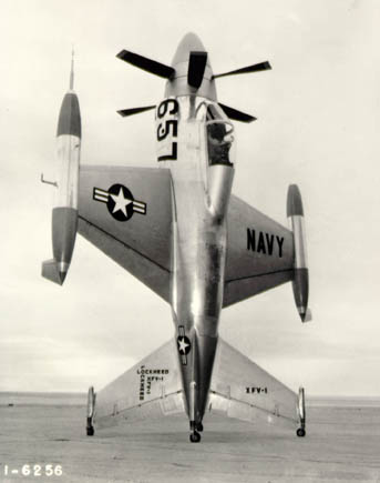
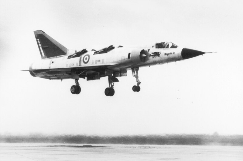
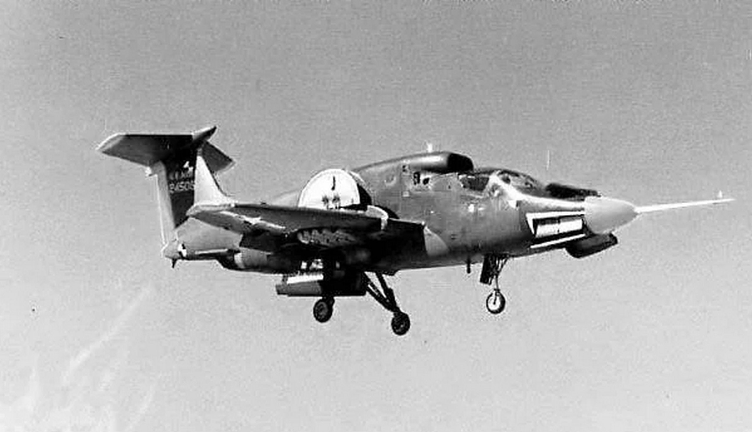
Work on tail-sitter types of VTOL airplanes was pursued in the 1940s and 1950s, proposing that an otherwise fairly conventional airplane could rest on its tail for takeoff and landing. The designs of the Convair XFY-1 “Pogo”, the Lockheed XFV-1, and the Ryan X-13 “Vertijet” were motivated primarily by the need for military fighters that could operate from forward operating bases without access to conventional runways. These ideas anticipated later operational experiments with tail sitters, but their capabilities were limited by inadequate control authority and underpowered engines.
With the development of powerful jet engines after WWII, a new generation of VTOL concepts emerged. The 1950s and 1960s saw an extensive exploration of jet-borne VTOL. Designs such as the Dassault Balzac, Mirage IIIV, and Yakovlev Yak-38 used dedicated lift jets or vertically vectored main engines to achieve vertical takeoff. Although technically impressive, most suffered from severe penalties in terms of payload, fuel consumption, and control complexity. These limitations kept them from becoming operationally successful, with the notable exception of the Harrier, to achieve practical VTOL performance and a long service life.
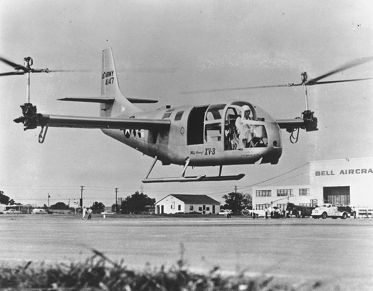
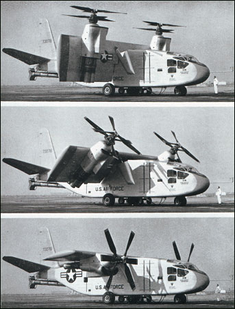
In parallel, considerable effort was devoted to tilting propulsion systems, another approach that sought to combine the vertical thrust needed for hover with the efficiency of a fixed-wing aircraft in forward flight. Early research prototypes such as the Bell XV-3, Bell XV-15, and Canadair CL-84 explored tiltrotor and tiltwing architectures. The XV-3 featured an engine mounted in the fuselage with driveshafts transferring power to two-bladed rotors mounted on the wingtips. The rotor assemblies were mounted to tilt from vertical to horizontal, allowing the XV-3 to take off and land like a helicopter but to fly at higher airspeeds than a helicopter. These programs provided the fundamental aerodynamic and control insights that eventually led to the V-22 Osprey, the first operational tiltrotor aircraft. Although these configurations still rely on relatively large rotors and so share some characteristics with helicopters, they represent a fundamentally different design philosophy, centered on powered lift from proprotors; proprotors are considered hybrids between propellers and rotors, with the attendant compromises of both.
Another line of VTOL aircraft development investigated ducted fans, internal lift fans, and blown-wing systems. The Ryan XV-5 Vertifan employed a fan-in-wing lift system to generate vertical thrust. First flown in 1964, it was powered by two jet engines feeding three vertically oriented fans, one in the nose and one embedded in each wing. The arrangement worked, but the aircraft remained difficult to handle during the transition between vertical and horizontal flight, with throttle changes resulting in rapid, often abrupt changes in flight attitude.
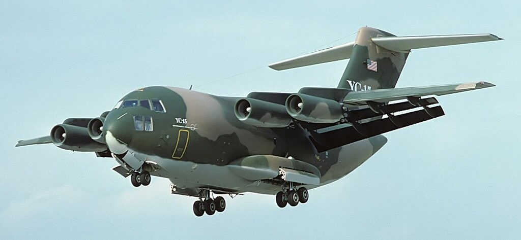
The Boeing YC-14 and McDonnell Douglas YC-15 demonstrated that upper-surface blowing over a fixed wing could produce remarkable lift without resorting to vertical thrust. Built for the Advanced Medium STOL Transport program as potential successors to the C-130, both prototypes achieved excellent low-speed and short-field performance. Although the programme did not proceed, several aerodynamic and systems concepts were later incorporated into the C-17.
Interest in non-helicopter VTOL has surged again in the 21st century, driven by advances in electric motors, high-power electronics, and autonomous flight control. These developments have enabled multirotor UAVs, lift-plus-cruise architectures, distributed electric propulsion, and electric tiltrotor or tiltwing concepts that would have been impractical with earlier technologies. Electric propulsion removes many of the mechanical complexities that limited earlier VTOL systems, improving redundancy, reducing maintenance, and expanding the viable design space for engineers.
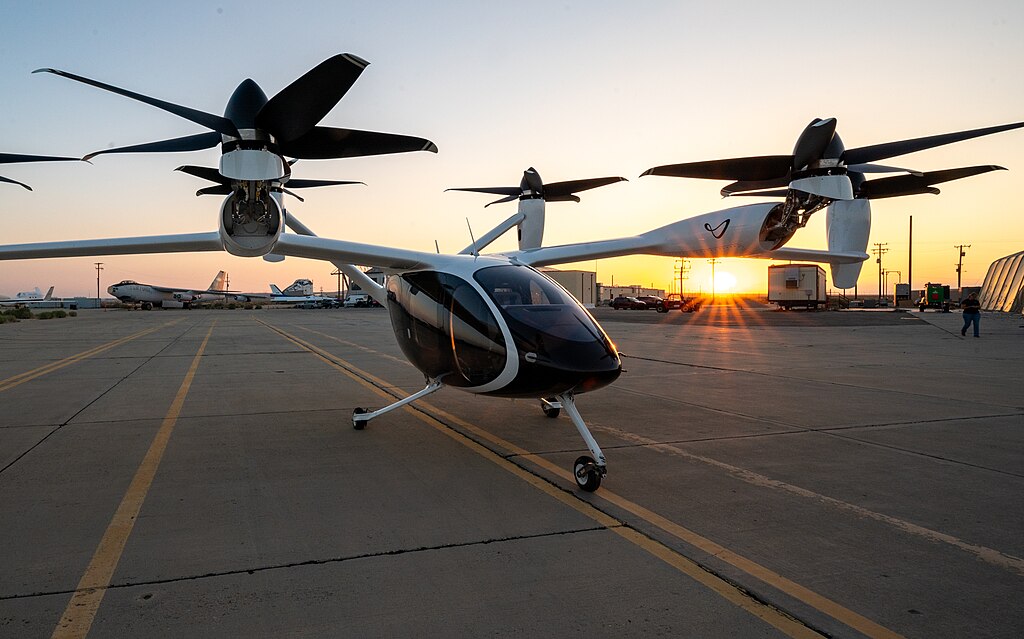
Hybrid quad-rotor configurations, often called quadcopters, as shown in the photograph below, use multiple electrically driven rotors for vertical lift and a fixed wing for forward flight. This arrangement has become common in uncrewed aerial vehicles (UAVs) and in many emerging electric VTOL (eVTOL) concepts. Although eVTOL aircraft remain constrained by the limited specific energy of current batteries, they are still the most active and rapidly evolving sector of VTOL research and development.
Disk Loading & Power Loading
For any VTOL aircraft, whether the lifting force is generated by a rotor, propeller, or jet exhaust, the disk loading is defined as the thrust per unit area over which momentum is imparted to the air. So, for an aircraft, if its weight  is supported by
  rotors or other lifting systems, then
  . This disk loading parameter is written as
  . For rotorcraft, the area
  is the physical disk area swept out by the rotor(s). For jet-thrust VTOL aircraft, however, the “effective” area is the cross-sectional area of the jet exhaust, which is much smaller compared to the area of a rotor. The consequence is that such vehicles have very high effective disk loadings because they accelerate a relatively small mass of flow with a very large “jet” velocity increment.
Notice that disk loading is measured in pounds per square foot (lb ft ) in the USC system or Newtons per square meter (N m) in SI. In the SI system, it is sometimes expressed in kilograms per square meter (kg m), although the kilogram is a unit of mass and its direct use as a surrogate for force is technically incorrect.
A related metric is power loading, defined as  where
where  is the power required, with units of lb hp
 in the USC system or N kW in SI units. Assuming the lifting system is modeled as an actuator disk, the momentum theory gives
(1) 
where the (ideal) induced velocity,  , is
, is
(2) 
This velocity is referred to as “ideal” because no losses attributable to viscosity have been assumed. Therefore, a low disk loading corresponds to a low induced velocity and a high power loading, meaning more thrust is produced per unit of input power. Naturally, the production power is reflected in the fuel consumption. Conversely, a high disk loading produces a high induced velocity, low power loading, and high fuel consumption, reflecting poor hovering efficiency.
The figure below shows the strong inverse relationship between power loading and disk loading when viewed on logarithmic axes. Vertical-lift devices with low disk loading achieve high hovering efficiency, requiring less power to generate thrust. As disk loading increases, power loading decreases rapidly, indicating a growing penalty in required power.
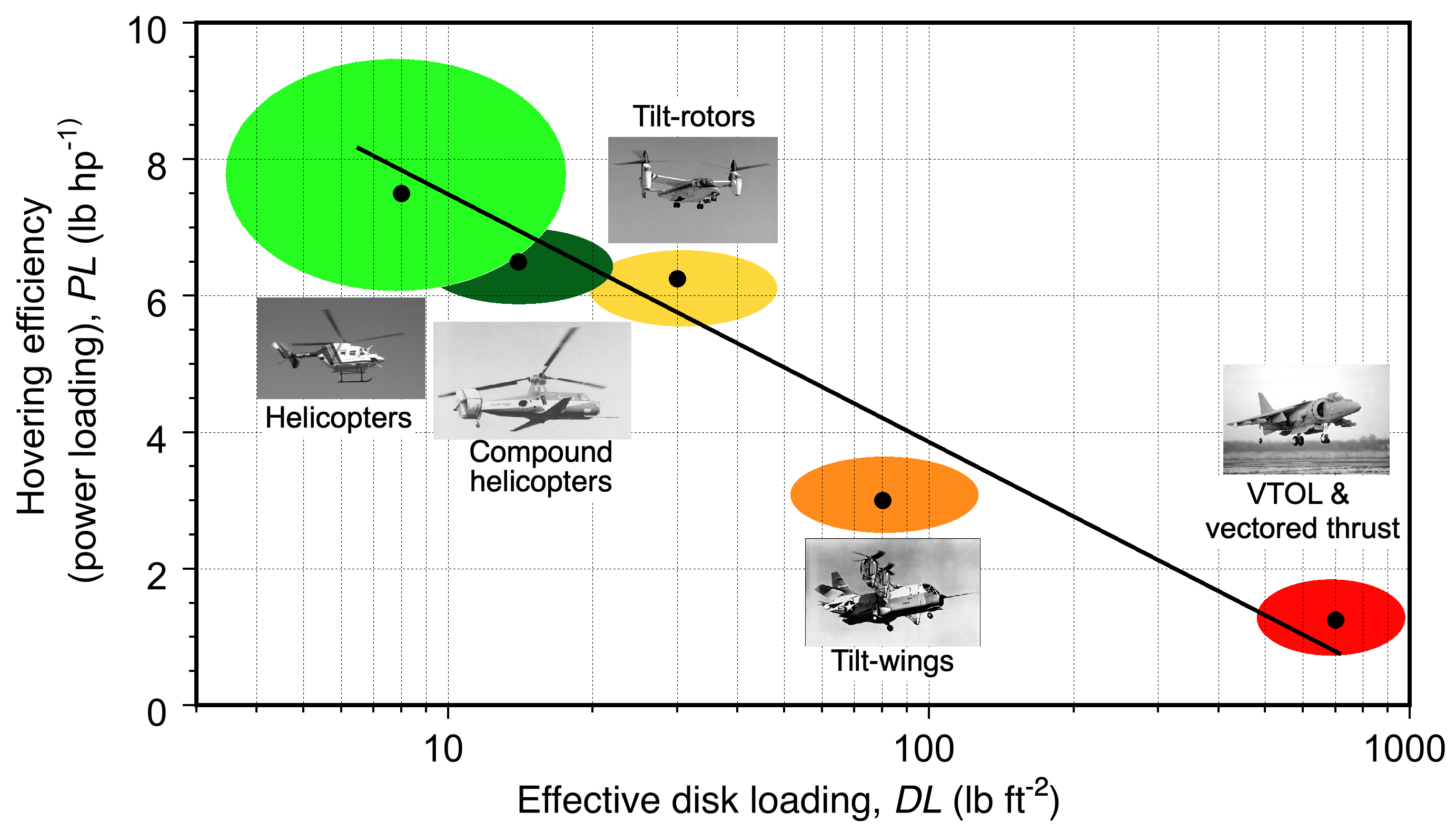
Helicopters occupy the low end of the disk-loading spectrum, with values typically between 5 and 10 lb ft (about 25 to 50 kg m). Their large rotor disks move a substantial mass of air with a comparatively small velocity increment, which results in excellent power loading and relatively low power requirements in hover. Tiltrotors operate at somewhat higher disk loadings because their rotors must also satisfy the constraints of efficient propulsion in forward flight; consequently, their hovering efficiency is lower than that of an equivalently sized helicopter of similar weight.
Jet-thrust VTOL aircraft occupy the high end of the disk-loading spectrum. The exit areas of jet nozzles and lift jets are small, and so the exhaust velocities are very large. The result is an extremely low power loading. In physical terms, jet-lift aircraft produce thrust by imparting a very large momentum increase to a small mass flow, rather than a modest momentum increase to a large mass flow. This approach is inherently inefficient in hover, leading to very high fuel consumption and limited hover endurance.
Taken together, these observations explain why jet-thrust VTOL concepts exhibit the poorest hovering efficiency of all vertical-lift systems, whereas rotor-based aircraft exhibit the best. The significant differences arise directly from the dependence of the induced velocity on disk loading and the fundamental aerodynamic constraints imposed by the mechanisms used to accelerate the air.
VTOL Jet-Thrust Airplanes
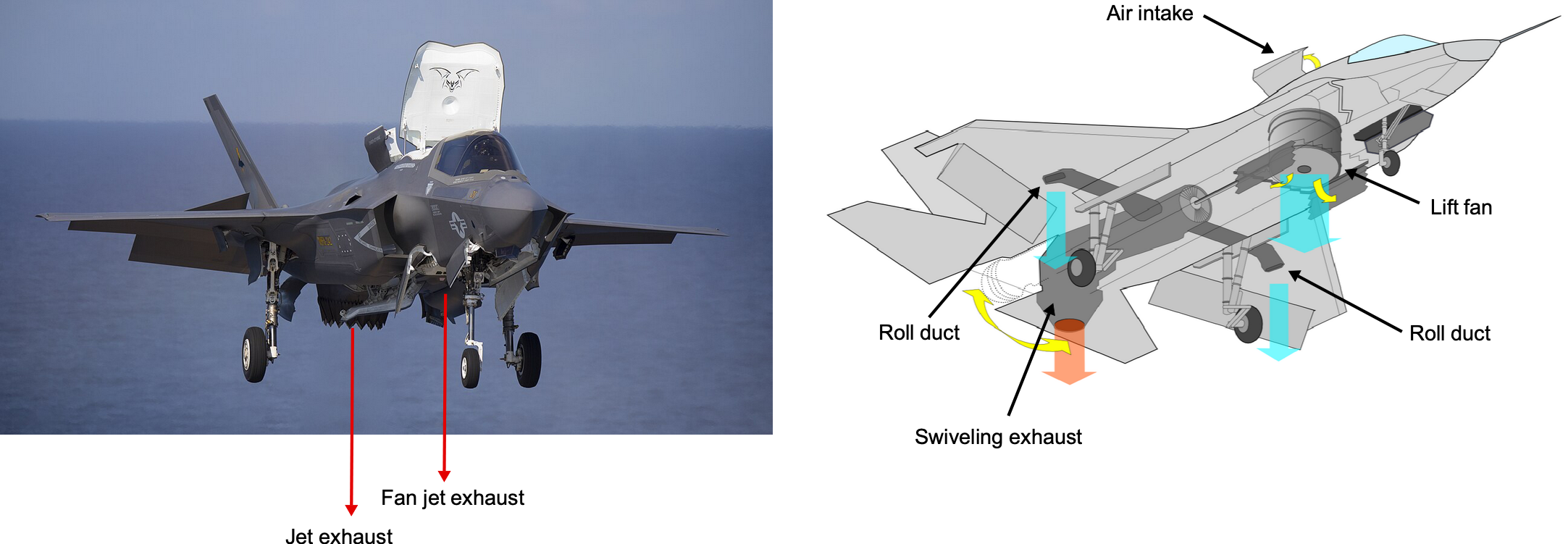
Only three of the numerous VTOL or V/STOL airplanes on the Wheel have succeeded and reached production. The best-known is the Harrier Jump Jet, which became the McDonnell-Douglas AV-8B Harrier. In recent years, a version of the Lockheed Martin F-35 Lightning Joint Strike Fighter, designed explicitly for V/STOL flight, has been developed (the F-35 B). This variant utilizes a powerful counter-rotating lift fan in the fuselage and a swiveling jet nozzle for vertical lift, inspired by the Russian Yak-141. The turbofan engine provides thrust for forward flight, but some of the power can also be diverted to a shaft to drive a dedicated lift fan for vertical takeoff and hovering, as shown in the figure below. Like the Harrier, the F-35B has two small nozzles in the wing to give roll control.
Jet Thrust
VTOL airplanes generate vertical thrust to take off, but hovering on jet thrust requires a substantial amount of power and fuel. The thrust for VTOL operation is governed by Newton’s second and third laws, i.e., from conservation of momentum, the jet thrust,  , is given by
(3) 
where  is the mass flow rate of exhaust gases,
  is the“jet” or “exit” velocity of the exhaust gases,
  is the exhaust pressure,
  is the ambient pressure at the inlet to the engine, and
  is the net or equivalent nozzle exit area. In most VTOL operations, the exit nozzles for vertical thrust are designed for ideal expansion so that
  , simplifying the thrust equation to
(4) 
To sustain hover, the net vertical thrust must balance the aircraft’s weight, i.e.,  . Therefore, a key metric for VTOL aircraft is the thrust-to-weight ratio (TWR), i.e.,
(5) 
For VTOL, a  is necessary to achieve takeoff and to initiate the flight into a vertical climb. Successful VTOL airplanes must have a TWR of at least 1.1, so just a modest excess thrust over and above that required to hover. The thrust requirements in forward flight are significantly less than those for hovering flight, allowing for impressive flight performance with excess thrust.
Aerodynamic Efficiency and Transition to Forward Flight
Hovering with pure jet thrust has high power requirements and is fuel-intensive. Therefore, VTOL jets transition quickly to aerodynamic lift, where the wings sustain flight more efficiently. The lift is given by the usual formula, i.e.,
(6) 
where  is the lift force,
  is the ambient air density,
  is the airspeed,
  is the maximum transition lift coefficient for the wing to start flying,
  is the wing area, and is the weight of the airplane. The transition speed at which aerodynamic lift replaces thrust-based lift will be
(7) 
This speed is crucial because the aircraft must accelerate to this airspeed to achieve routine wing-borne flight. In the Harrier, for example, the transition process is relatively seamless. The pilot gradually swivels the nozzles back, and the airplane accelerates quickly to the required airspeed to achieve full wing-borne flight.
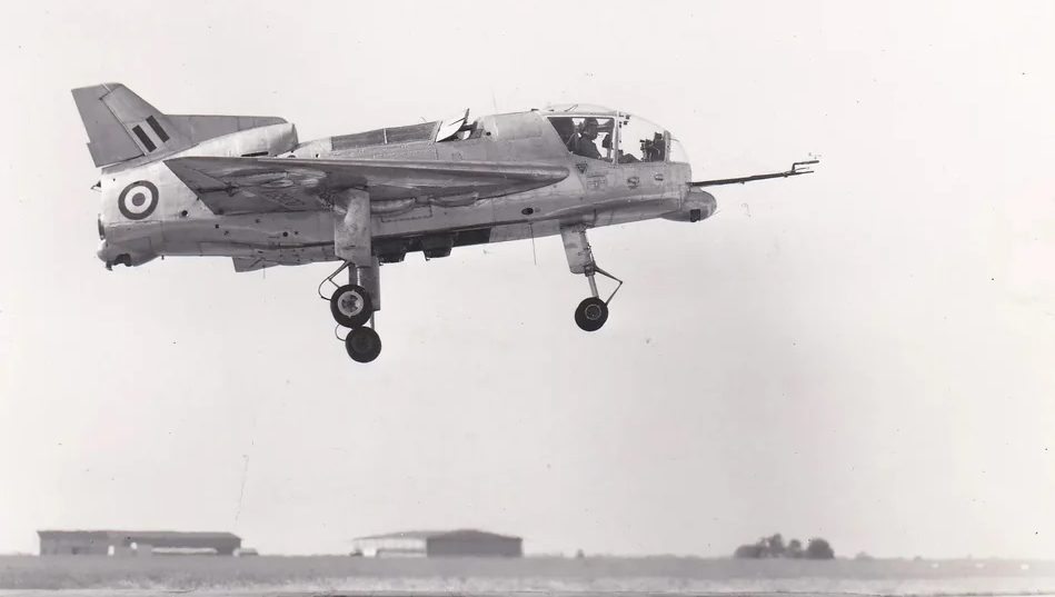
Harrier Thrust Vectoring System
The Harrier utilizes a unique thrust-vectoring system known as the “four-poster” configuration. This configuration consists of four small rotating nozzles positioned in pairs beneath the wings, as shown in the photographs below. The nozzles can be directed straight downward for hovering, fully aft for forward flight, or at intermediate angles to facilitate short takeoff, landing, and in-flight maneuverability.
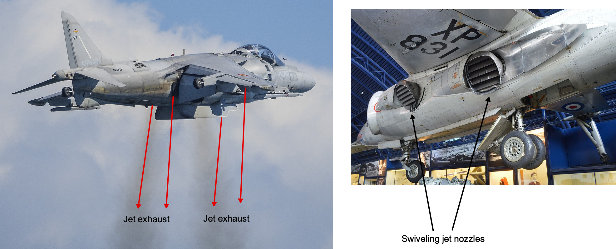
A feature of the Harrier is that all four swiveling nozzles, along with the roll-control jets in the wingtips, are powered by a single turbofan engine. This integrated propulsion system eliminates the need for dedicated lift engines but requires the engine to be positioned close to the aircraft’s center of gravity to maintain trim and effective control. Thrust vectoring gives the Harrier exceptional versatility, allowing operations from short runways, aircraft carriers, and rough or improvised sites. However, it also brings high pilot workload, high hover fuel consumption, and strict limits on payload and munitions when operating in full VTOL mode. Whenever sufficient runway is available, rolling takeoffs are preferred because they allow substantially greater takeoff weight.
A vertical takeoff is performed by rotating the nozzles downward so that the jet exhaust produces a nearly vertical lifting force. Let  denote the nozzle angle measured from the horizontal, with
  corresponding to the VTOL setting. The vertical thrust component is then
  , where is the total engine thrust. A vertical liftoff requires
  where is the aircraft’s weight. After advancing the power, the aircraft lifts into a steady hover a few feet above the ground to confirm a thrust margin before climbing vertically. Once airborne, the Harrier climbs vertically while maintaining approximately level attitude, as shown in the figure below. With little or no forward speed, it is entirely jet-borne, and the wings generate negligible lift.
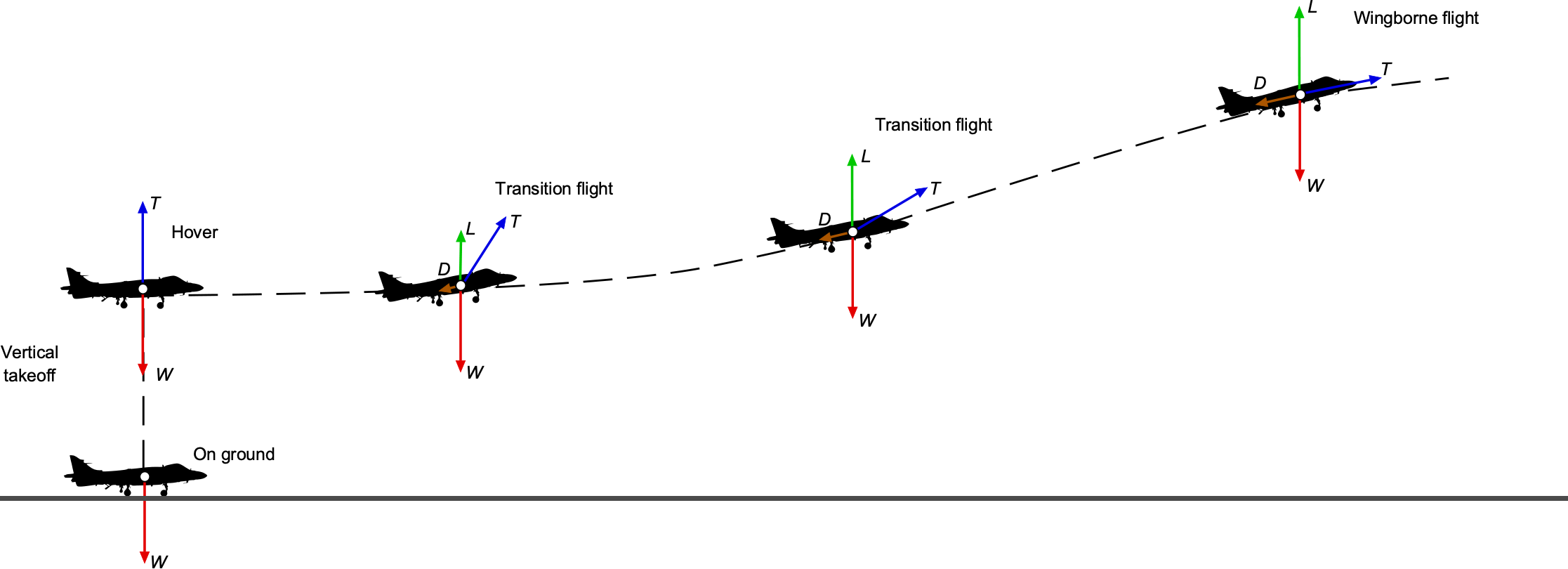
Above a safe height, the pilot begins the transition toward wing-borne flight by rotating the nozzles aft. As the nozzles move from  toward
  , a forward thrust component
  is produced, accelerating the aircraft. As the forward speed increases, the wings begin to generate lift, and the aircraft gradually transfers from jet-borne to wing-borne flight. When sufficient wing lift is available, the nozzles are rotated further aft toward conventional flight settings (
 ). Because the available vertical thrust decreases rapidly with increasing aircraft weight, temperature, and altitude, pure VTOL takeoffs are feasible only when the aircraft is lightly loaded. Operational missions carrying significant fuel and weapons almost always require a short rolling takeoff or, when operating from a carrier, a ski-jump to achieve safe takeoff.
Check Your Understanding #1 – Calculating the power and fuel consumption for the Harrier
Estimate the thrust, power, and fuel consumption for the Harrier AV-8B when it is hovering. Also, calculate the transition airspeed to wing-borne flight. The following parameters are readily available for the Harrier (AV-8B) airplane: Mass  kg, engine type Rolls–Royce Pegasus 11-61 with an exhaust velocity
  m/s, wing area
  m², wing transition lift coefficient
  , and propulsive efficiency
  .
.
Show solution/hide solution.
Based on the weight of the airplane, the thrust required for hovering flight is
![\[ T_{\text{req}} = W = M g = 9{,}400 \times 9.81 = 92{,}214~\text{N} = 92.2~\text{kN} \]](https://eaglepubs.erau.edu/app/uploads/quicklatex/quicklatex.com-60e0f7cbebe24d7ba40577650544b11f_l3.svg "Rendered by QuickLaTeX.com")
To sustain hover, the engine must provide 92.2 kN of thrust, which means the net mass flow rate (all four nozzles) must be
![\[ \dot{m} = \frac{T_{\text{req}}}{v_e} = \frac{92{,}214}{550} = 167.7~\text{kg/s} \]](https://eaglepubs.erau.edu/app/uploads/quicklatex/quicklatex.com-14d2396a7d1a77f15af62318a355c801_l3.svg "Rendered by QuickLaTeX.com")
Therefore, the Pegasus engine must expel the exhaust at a net mass flow rate of about 168 kg/s with an exhaust velocity of 550 m/s. The power associated with the jet exhaust can be estimated as
![\[ P \approx \frac{T_{\text{req}} \, v_e}{\eta} = \frac{92{,}214 \times 550}{0.5} = 1.014\times 10^{8}~\text{W} = 101.4~\text{MW} \]](https://eaglepubs.erau.edu/app/uploads/quicklatex/quicklatex.com-ef51089de883fd4096a0d459138870b1_l3.svg "Rendered by QuickLaTeX.com")
Hovering requires a high power level, which explains the very high fuel consumption in VTOL mode. The thrust-specific fuel consumption (TSFC) of the Rolls–Royce Pegasus engine is approximately
![\[ \text{TSFC} \approx 0.76~\text{lb}~(\text{lb hr})^{-1} \]](https://eaglepubs.erau.edu/app/uploads/quicklatex/quicklatex.com-959a7802820c8526fd2a9b17baf448eb_l3.svg "Rendered by QuickLaTeX.com")
which converts to
![\[ \text{TSFC} \approx 2.15\times 10^{-5}~\text{kg}~(\text{N s})^{-1} \approx 7.75\times 10^{1}~\text{kg}~(\text{kN hr})^{-1} \]](https://eaglepubs.erau.edu/app/uploads/quicklatex/quicklatex.com-dc7b71c7b40479d98733816527c931d8_l3.svg "Rendered by QuickLaTeX.com")
So, the fuel mass flow rate in hover at  is
is
![\[ \dot{m}_f = \text{TSFC}\,T_{\text{req}} = 2.15\times 10^{-5} \times 92{,}214 \approx 1.99~\text{kg/s} \approx 7{,}150~\text{kg/hr} \]](https://eaglepubs.erau.edu/app/uploads/quicklatex/quicklatex.com-e6c4b8e9ea3faed1f9bf99bfc8d14c6c_l3.svg "Rendered by QuickLaTeX.com")
The AV-8B has an internal fuel capacity of about 3,402 kg (7,500 lb), so if it attempted to hover continuously at this thrust level, the internal fuel alone would last only
![\[ t_{\text{hover,int}} \approx \frac{3{,}402}{7{,}150} \approx 0.48~\text{hr} \approx 29~\text{min} \]](https://eaglepubs.erau.edu/app/uploads/quicklatex/quicklatex.com-f15a8cea11d0068c61336fc5ecad683d_l3.svg "Rendered by QuickLaTeX.com")
and with up to three external drop tanks, the total fuel capacity increases to 6,122 kg, giving at most
![\[ t_{\text{hover,total}} \approx \frac{6{,}122}{7{,}150} \approx 0.86~\text{hr} \approx 52~\text{min} \]](https://eaglepubs.erau.edu/app/uploads/quicklatex/quicklatex.com-5a30071bbd1e3a07c6657741e8eb39d1_l3.svg "Rendered by QuickLaTeX.com")
of continuous hover. In practice, operational hover times are much shorter because the aircraft does not remain at full hover thrust for long, reserves must be maintained, and vertical operations are confined to brief periods during takeoff and landing.
The transition speed from hovering to fully wing-borne flight is
![\[ V_{\text{trans}} = \sqrt{\frac{2 \,W}{\varrho_{\infty}\,C_{L_{\rm trans}}\,S}} = \sqrt{\frac{184{,}428}{32.07}} = 75.9~\text{m/s} = 273~\text{km/h} = 147.4~\text{kts}.] \]](https://eaglepubs.erau.edu/app/uploads/quicklatex/quicklatex.com-b8a67494386ab9c9bdcc9fdc9b6fb2be_l3.svg "Rendered by QuickLaTeX.com")
Therefore, the Harrier must reach about 147 kts before fully transitioning so it can fly with full aerodynamic lift on the wings.
Lift-Jet VTOL Concepts
Another category of VTOL jet-thrust airplanes uses dedicated vertical-lift engines, or lift jets. These aircraft carry several small turbojets near the center of gravity that provide vertical thrust for takeoff, hover, and landing, while a separate main engine propels the airplane in forward flight. This approach was widely explored from the 1950s to the 1970s. It produced several notable prototypes, including the Dassault Balzac V and Mirage IIIV, as well as the British Short SC.1 and the Soviet Yakovlev Yak-38. Although technically ambitious, these aircraft suffered from severe payload penalties, high pilot workload, and the risk of catastrophic loss if a single lift jet failed. They remain prominent examples on the V/STOL Wheel, illustrating the inherent shortcomings of using dedicated lift jets for vertical flight.
In a lift-jet concept, the vertical engines are placed near the aircraft’s center of gravity so that their thrust lines pass close to the mass centroid and avoid large trim moments in hover. During vertical operations, the lift jets supply downward momentum to balance the airplane’s weight, as has been previously described. In forward flight, these engines are shut down, their inlets close, and they become inert mass for the remainder of the mission. The fundamental penalty of this configuration can be illustrated with a simple dead-weight fraction argument. If the aircraft requires a total hover thrust equal to its weight , and lift jets are used, then each engine must provide roughly  . If the installed weight of each lift engine and its supporting structure is
  , then the fraction of aircraft weight that becomes non-useful in cruise is
(8) 
Historical lift-jet aircraft typically had  values of 0.15 to 0.25, imposing severe payload and range penalties. Lift jets also have high specific fuel consumption during hover, further reducing mission efficiency.
A second inherent limitation concerns failure tolerance. If the lift jets are separated laterally by a distance  , the loss of one engine producing thrust creates an immediate roll moment of approximately
(9) 
This moment greatly exceeded the available roll-control authority on early lift-jet aircraft, and the resulting roll acceleration was often unrecoverable.
Despite these issues, several notable lift-jet aircraft were built and flown. The French Dassault Balzac V and Mirage IIIV used eight lift jets along with a main propulsion engine for forward flight. The Soviet Yakovlev Yak-38 also employed dedicated lift engines combined with a swiveling main nozzle. Although it achieved limited operational service, its payload, range, and safety record were poor. The Short SC.1 was the first British fixed-wing VTOL jet aircraft. It was powered by an arrangement of five Rolls-Royce RB.108 turbojets, four of which were used for vertical flight and one for conventional horizontal flight. The SC.1 was the first British fixed-wing VTOL aircraft and the first to transition between vertical and horizontal flight modes; it was also the first VTOL-capable aircraft with a fly-by-wire control system. The Bell X-14 was one of the few successful research aircraft in this category, mainly because of its simplicity and low operating weight.
The historical conclusion is clear. Concepts using lift jets can provide vertical thrust, but they impose a significant weight penalty in cruise and are highly vulnerable to asymmetric thrust failures. These shortcomings motivated the more successful Harrier, whose single engine eliminated the dead-weight problem through integrated vectored thrust, and later the F-35B, which uses a shaft-driven lift fan that can be disengaged in forward flight. Although lift-jet aircraft were ultimately a technological dead end, they clarified the aerodynamic, control, and structural challenges that any practical VTOL aircraft must address.
Ducted Rotor VTOL Concepts
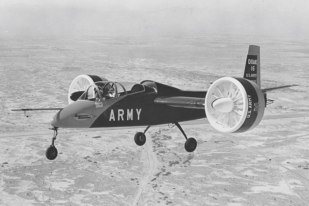
Ducted-rotor VTOL aircraft use one or more rotors enclosed within an annular shroud to generate vertical lift. The duct reduces tip losses, modifies the wake development, and can provide a significant increase in static thrust when it is properly shaped. These ideas have been explored for decades in VTOL experiments such as the Ryan XV-5 Vertifan and the Doak VZ-4, and they reappear today in many smaller UAVs and eVTOL concepts. Because the rotor is enclosed in an annular duct, its aerodynamic behavior differs from that of an open rotor, and the duct can enhance safety by shielding the blades and reducing high-frequency tip noise. The main advantages of a ducted rotor are its more compact size, improved static thrust for a given rotor diameter, and the protective function of the duct. These benefits make ducted rotors appealing for small aircraft that operate near people or in confined spaces.
However, the duct introduces penalties that limit broader application. Structural requirements add significant weight, and the duct produces substantial drag in forward flight, which reduces cruise efficiency. Performance can also deteriorate rapidly in crosswinds when the flow separates at the lip of the duct, and multiple ducts placed close together may interact unfavorably. For these reasons, ducted rotors are most effective when compactness, safety, and moderate hover efficiency outweigh the need for long-range performance or high forward speed.
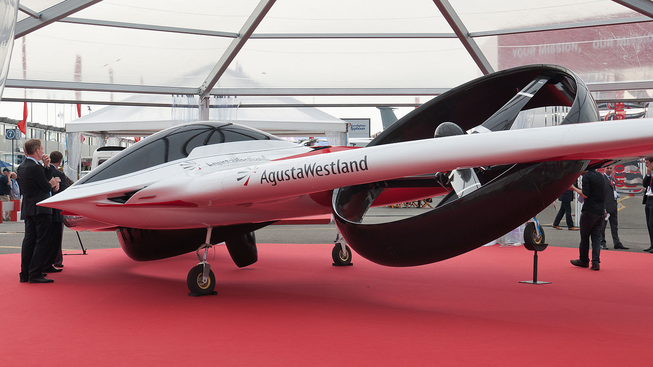
The Agusta-Westland Project Zero was an experimental aircraft built to explore the use of electrically driven ducted rotors for VTOL and forward flight. Each rotor was fully enclosed within a duct, reducing tip losses in hover, while the entire ducted-rotor assembly can tilt to transition between vertical lift and wing-borne cruise. As the world’s first all-electric tiltrotor, Project Zero demonstrated how ducted rotors can be integrated into a compact airframe to provide vertical lift, while also highlighting the aerodynamic and control challenges associated with operating ducted rotors across a wide flight envelope.
Theory of Ducted Rotors
Many theoretical models have been developed to predict the thrust and power characteristics of ducted rotors and fans. Foundational work was done by Krüger[1] and by Kuchemann and Weber[2] who have applied the principles of the momentum theory to analyze ducted rotor flows. Mort[3] and Mort and Gamse[4] provided experimental data and corrections for tip clearance and swirl losses. Lee[5] provides a more recent exposition of the performance of single- and coaxial-ducted rotors in hover and forward flight.
Numerous experiments have demonstrated that the downstream wake from a ducted rotor tends to follow the duct walls as it interacts with the internal surfaces. If the duct walls are adequately contoured (e.g., gently curved or flared in a diffuser-like manner), the flow tends to remain attached to the duct walls, which is a form of Coandă effect. This effect suppresses the natural contraction of the wake found with an unducted rotor, so maintaining a larger effective flow area and higher static pressure in the wake. The upshot is an augmented thrust on the rotor and pressure force on the duct, thereby increasing the net system thrust for a given power input.
Flow Model
The momentum theory of a ducted rotor or fan can be developed as an extension of classical actuator-disk theory, with modifications to account for the constrained wake and the flow properties imposed by the duct. The flow model is illustrated in the figure below. Ultimately, the analysis, including the incorporation of non-ideal effects, is not as “clean” or as easily generalized as for the unducted or open rotor. Still, the application of the underlying principles remains the same, including the use of the conservation laws of mass, momentum, and energy, as well as consideration of various quantifiable sources of non-ideal losses, such as tip-gap effects.
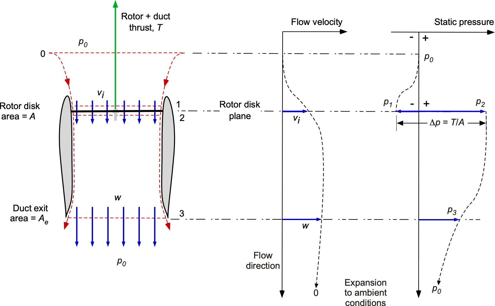
Far upstream of the rotor (station 0), the flow velocity is zero, and the static pressure is  . At the rotor disk, the induced velocity is denoted , as before, and there is a pressure jump across the disk. Because the shape and length of the duct allow some degree of control over the development of the rotor wake, the effective area of the slipstream at the exit becomes
  rather than
  for the open rotor. The corresponding relative exit velocity is denoted by
  .
.
Experiments have shown that the rotor wake tends to follow the duct walls because it interacts with the duct’s internal surfaces. If the duct walls are adequately contoured, i.e., they are sufficiently long and gently flared at the exit in a diffuser-like manner, thereby ensuring the flow remains attached to the duct walls. This behavior suppresses the natural contraction of the wake, maintaining a larger effective flow area and higher static pressure at the exit (station 3). The residual wake then expands into the ambient fluid, with the static pressure recovering asymptotically to , while the velocity decays more slowly because of the convected momentum flux. This latter behavior satisfies the far-field boundary conditions typical of actuator-disk models, including the open-rotor case previously analyzed.
Conservation Laws
The conservation principles can be applied to the rotor in the duct flow model, just as they are for the isolated rotor. Using the principle of conservation of mass gives
(10) 
Solving for the downstream velocity, , gives
(11) 
Conservation of momentum gives the total thrust produced by the rotor and its duct as a system. Considering a control volume from far upstream (station 0) to the duct exit (station 3), the total thrust is given by
(12) 
Substituting  gives
gives
(13) 
This equation shows that the total thrust is the sum of a momentum contribution and a static pressure difference acting on the duct. If  , then the pressure difference contributes to the net system thrust, depending on whether the flow is over-expanded or under-expanded. More fundamentally, the duct enables pressure control at the rotor exit, i.e., it allows the pressure gradient between station 2 and station 3 to be shaped by the duct geometry. The aerodynamic benefit of the duct primarily arises from its ability to maintain a higher pressure at its exit, which is a consequence of suppressing wake contraction.
Regarding energy conservation, Bernoulli’s equation can be applied from upstream (station 0) to just before the disk (station 1), i.e.,
(14) 
Recall that the Bernoulli equation cannot be applied across the disk where there is energy addition. However, Bernoulli’s equation can be applied from just after the rotor disk (station 2) to the exit plane (station 3), i.e.,
(15) 
Subtracting these two latter equations eliminates the ambient pressure, , and gives the pressure rise across the rotor disk as
(16) 
Notice that if  , then the open rotor case is recovered.
Thrust & Power
The rotor or fan thrust is defined as the net pressure force across the rotor disk, i.e.,
(17) 
The total thrust acting on the system is the sum of the momentum flux and the pressure force acting on the duct exit, i.e.,
(18) 
Using  and gives
(19) 
Subtracting the rotor thrust from the total thrust gives the residual thrust produced by the duct alone, i.e.,
(20) 
Using the actuator disk relation
(21) 
and  , this becomes
(22) 
This result shows that the duct contributes both a static-pressure component and a momentum component whenever  .
.
The induced power required by the fan is the product of the fan thrust and the induced velocity, i.e.,
(23) 
Using  and gives
(24) 
The total induced power for the ducted system is
(25) 
If the downstream pressure equals the ambient pressure (), the classical actuator disk results for an unducted open rotor are recovered. For an open rotor,
(26) 
For a ducted rotor with exit area ratio  , the same thrust is produced with induced velocity
  , giving
(27) 
Taking the ratio gives
(28) 
showing the fundamental duct advantage: reduced induced power at a given thrust.
Finally, notice that two interpretations of effective disk loading,  , are possible. The first is a geometric interpretation:
(29) 
which leads directly to
(30) 
An alternative (more physical) definition accounts for the static-pressure thrust contribution of the duct:
(31) 
The two definitions coincide only in the ideal limit when the duct provides full pressure recovery at the expanded wake area.
Measured Performance
An example of the aerodynamic benefits of a ducted rotor is shown in the figure below, which presents a measured power polar for a small UAV system. Measurements were taken both with and without the duct in place. Because this rotor utilizes variable rotor speed to adjust the thrust, the results are normalized with respect to a design reference condition. Notice the substantial increase in net system thrust with the addition of the duct. However, one must be cautious in interpreting these results. While the use of a duct can certainly increase rotor thrust for a given power input, or equivalently, reduce power required for a given thrust, these aerodynamic benefits must be weighed against the added weight of the duct. If the added weight offsets the thrust benefit at the system level, then there may be no net performance gain.
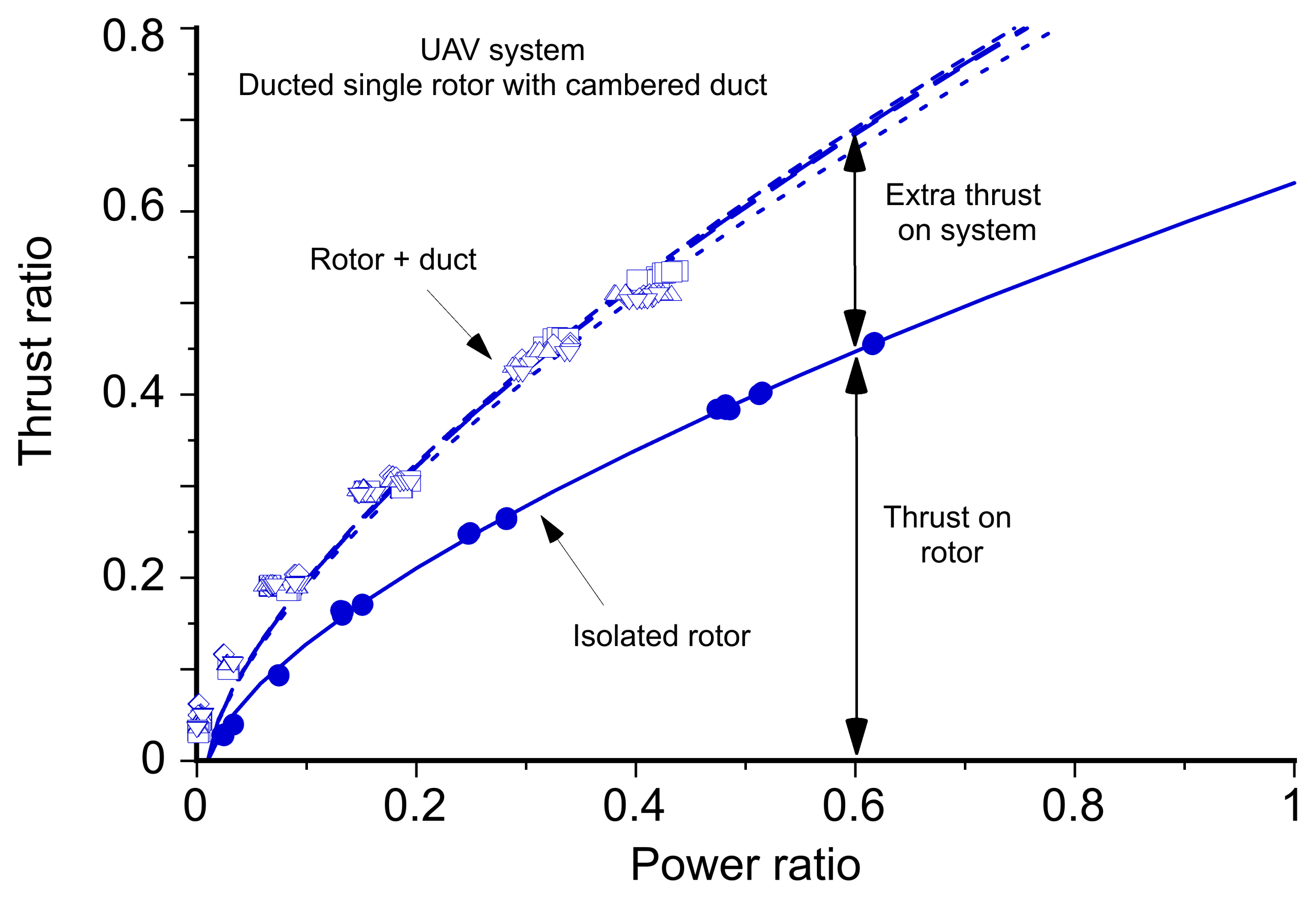
Nevertheless, there are reasons beyond performance to consider with a ducted rotor. In particular, ducts improve safety by shielding the rotor blades, reducing the risk of personnel injury or damage during ground operations. This issue is significant for small UAVs operating near people or obstacles. Ducts can also reduce noise by shielding an observer from the spinning rotor, which is a significant advantage for urban or low-observability applications. In such cases, the tradeoff between aerodynamic efficiency and total system functionality may still favor the use of a duct.
Losses
In general, while the momentum theory provides a valuable framework for analyzing ducted rotors and fans, it is challenging to generalize because the duct’s shape ultimately affects both the rotor’s performance and the duct’s impact on the rotor. The duct also affects the rotor. Yet it demonstrates how a well-designed, suitably shaped duct can help control the development of the slipstream, thereby reducing the power required to produce a given thrust. To be aerodynamically effective, the duct has to be relatively deep and long, which may incur a significant weight penalty. So-called “ring” ducts, which are short circular shrouds seen on many eVTOL concepts, do nothing to enhance rotor performance and so act as deadweight in this regard. Practical ducted rotor designs must also account for and incorporate corrections for profile drag on the blades, tip gap leakage, swirl losses, and duct losses to produce realistic net system (rotor plus duct) performance predictions. These effects can be encapsulated in an overall efficiency analogous to an induced power factor and a figure of merit used for an open rotor.
Tip Clearance
Tip clearance between the rotor blade tips and the duct wall causes leakage flows and a reduced pressure jump across the rotor disk. A small radial clearance gap  is always needed between the blade tips and the duct wall, as well as some allowance for blade lengthening from centrifugal forces. Even though this gap is typically very small, it always allows some flow leakage and reduces thrust. A commonly used correction to the thrust is
(32) 
where  is an empirical coefficient, typically between 0.1 and 0.2, is the measured or estimated tip gap under rotating conditions, and
  is the rotor radius. Because the induced power scales with
  , the corresponding increase in the induced power required to restore the lost thrust is given by
(33) 
Swirl Losses
Swirl losses, which result from rotational kinetic energy imparted to the slipstream, also reduce the effective axial thrust. Experiments have demonstrated that these effects can be significant on ducted rotors, which are typically smaller than helicopter rotors and so they rotate at higher angular velocities. These effects can reduce the expected performance predicted by ideal momentum theory, necessitating empirical corrections or more advanced modeling. Some ducts incorporate sets of stator vanes to recover the swirl and reduce losses. Otherwise, a swirl loss correction factor can be applied using
(34) 
where  is a fractional power penalty, typically in the range 0.05 to 0.15.
Profile Losses
Momentum theory concerns only induced losses, so profile losses must be added to the induced power requirements, as done for an open rotor. This component can be estimated using blade-element theory and depends on the blade area and the aerodynamic drag coefficients of the airfoil sections. An approximate representation of profile power is often written as
(35) 
where  is the angular velocity of the rotor,
  is the number of blades,
  is the weighted average blade chord, and
  is the average drag coefficient of the airfoils that make up the blades. Ducted rotors and fans often have large hubs, which can be accommodated using the root cutout distance
  .
.
Duct Losses
Ducts themselves also introduce pressure losses resulting from boundary layer thickening, flow separation, skin friction on the duct walls, and adverse pressure gradients. These effects are difficult to generalize, but can be modeled approximately using a multiplicative loss factor on the ideal induced power, i.e.,
(36) 
where  is an empirically determined coefficient representing the internal duct losses. Typically, is between 1.05 and 1.2.
Net Losses
In the context of the momentum equations, these corrections accumulate, so each source of loss contributes to the total power required by the system. The net system power required by the ducted rotor is then given by
(37) 
or, equivalently,
(38) 
where  is analogous to the induced-power factor for an unducted or open rotor, i.e.,
(39) 
Alternatively, to express the performance of the system in a compact form, a net system efficiency can be defined as
(40) 
where
(41) 
is the ideal induced power from momentum theory. This expression encapsulates all physical sources of loss for a ducted rotor system into a single overall performance metric, analogous to a figure of merit.
Like other rotor systems, such as coaxials and tandems, the ducted rotor theory has limited predictive capabilities without experimental validation. Therefore, the foregoing correction coefficients must be estimated or measured, and practical duct design methods typically rely on empirical calibration or CFD simulations for further performance validation.
Check Your Understanding #2 – Power required for a ducted rotor
A small vertical lift rotor system is required to produce a thrust of = 200 N in hover at sea level. The rotor has a radius of = 0.4 m, and is installed in a duct with an exit area expansion ratio of = 1.2. A pressure sensor on the duct indicates that the pressure at its exit is 300 Pa above ambient. Assume that the rotor is also evaluated in an open configuration (no duct), producing the same thrust. Compare the induced power required by the ducted rotor to that of the open rotor.
Show solution/hide solution.
The area of the rotor disk is
![\[ A = \pi R^2 = \pi (0.4)^2 = 0.503~\text{m}^2 \]](https://eaglepubs.erau.edu/app/uploads/quicklatex/quicklatex.com-9a2431efddbe61a213c8f5669443f1ef_l3.svg "Rendered by QuickLaTeX.com")
Using mass conservation, the exit velocity is related to the induced velocity by
![\[ w = \frac{v_i}{a_w} \]](https://eaglepubs.erau.edu/app/uploads/quicklatex/quicklatex.com-2c04ae7c1d58d3ee6a8a2de3c6b34ede_l3.svg "Rendered by QuickLaTeX.com")
Applying the thrust equation for a ducted rotor, the total thrust is
![\[ T = \frac{\varrho_{\infty} \, A\, v_i^2}{a_w} + (p_3 - p_0) a_w \, A \]](https://eaglepubs.erau.edu/app/uploads/quicklatex/quicklatex.com-6f238f85770053d22d6edff6a736c36e_l3.svg "Rendered by QuickLaTeX.com")
Solving for gives
![\[ v_i = \sqrt{ \frac{a_w\left[ T - (p_3 - p_0) a_w \, A\right]} {\varrho_{\infty} \, A} } \]](https://eaglepubs.erau.edu/app/uploads/quicklatex/quicklatex.com-3ea1b85210454994c6fcaa5a1611d3ff_l3.svg "Rendered by QuickLaTeX.com")
Substituting the given values, leads to
![\[ v_i = \sqrt{ \frac{1.2\left(200 - 300 \times 1.2 \times 0.503\right)} {1.225 \times 0.503} } = 6.08~\text{m/s} \]](https://eaglepubs.erau.edu/app/uploads/quicklatex/quicklatex.com-87a9a291ad2d70d7baa07293d734c0f6_l3.svg "Rendered by QuickLaTeX.com")
Therefore, the downstream velocity is
![\[ w = v_i/a_w = 5.07~\text{m/s} \]](https://eaglepubs.erau.edu/app/uploads/quicklatex/quicklatex.com-2bece152c0cb7c168f00e58839174607_l3.svg "Rendered by QuickLaTeX.com")
The fan thrust is the pressure jump across the rotor disk, i.e.,
![\[ T_{\text{fan}} = (p_2 - p_1) A \]](https://eaglepubs.erau.edu/app/uploads/quicklatex/quicklatex.com-dd7f9a48e751638acc2a5d370a90f3db_l3.svg "Rendered by QuickLaTeX.com")
where
![\[ p_2 - p_1 = \frac{1}{2}\varrho_{\infty}\left(w^2 - v_i^2\right) \]](https://eaglepubs.erau.edu/app/uploads/quicklatex/quicklatex.com-c21800fe503203cbb1970bfd09e89ab5_l3.svg "Rendered by QuickLaTeX.com")
Evaluating the thrust gives
![\[ T_{\text{fan}} = 8.65~\text{N} \]](https://eaglepubs.erau.edu/app/uploads/quicklatex/quicklatex.com-28581bd6c51ba73f7a4faea8f0d49350_l3.svg "Rendered by QuickLaTeX.com")
Therefore, the duct provides the remainder of the total thrust, i.e.,
![\[ T_{\text{duct}} = 200 - 8.65 = 191.35~\text{N}. \]](https://eaglepubs.erau.edu/app/uploads/quicklatex/quicklatex.com-5b628ea7facce01ed3386aa6e4e67efc_l3.svg "Rendered by QuickLaTeX.com")
The induced power required by the fan is
![\[ (P_i)_{\text{fan}} = T_{\text{fan}} \, v_i = 52.6~\text{W} \]](https://eaglepubs.erau.edu/app/uploads/quicklatex/quicklatex.com-b0018db6626d549efd4f2cdca100c968_l3.svg "Rendered by QuickLaTeX.com")
and the total induced power for the system is
![\[ (P_i)_{\text{total}} = T \, v_i = 1,216~\text{W} \]](https://eaglepubs.erau.edu/app/uploads/quicklatex/quicklatex.com-2a2335f571fd2cd17f7d520c2668ae45_l3.svg "Rendered by QuickLaTeX.com")
For comparison, the induced power of an open rotor is
![\[ (P_i)_{\text{open}} = \frac{T^{3/2}}{\sqrt{2 \, \varrho_{\infty} \, A}} = 2,556~\text{W} \]](https://eaglepubs.erau.edu/app/uploads/quicklatex/quicklatex.com-4982252d13519a91af2fd4134fd783bc_l3.svg "Rendered by QuickLaTeX.com")
Therefore, the ducted rotor requires only about half the induced power of an open rotor for the same thrust.
Tail-Sitter VTOL Aircraft
The tail-sitter configuration was one of the earliest attempts to achieve VTOL flight using a single, fixed airframe geometry. An aircraft of this type takes off and lands in a nose-up, vertical attitude, supported entirely by propulsive thrust, and transitions to horizontal flight by pitching forward until the wings produce the necessary aerodynamic lift. The essential appeal of the concept lies in its structural and mechanical simplicity. Unlike tiltrotors, tiltwings, or hybrid configurations employing complex mechanisms or multiple propulsion systems, the tail-sitter performs all phases of flight using a single, fixed propulsion unit and an unmodified wing planform. This simplicity proved attractive to designers during the late 1940s and 1950s, when the first serious investigations into VTOL operations were undertaken.
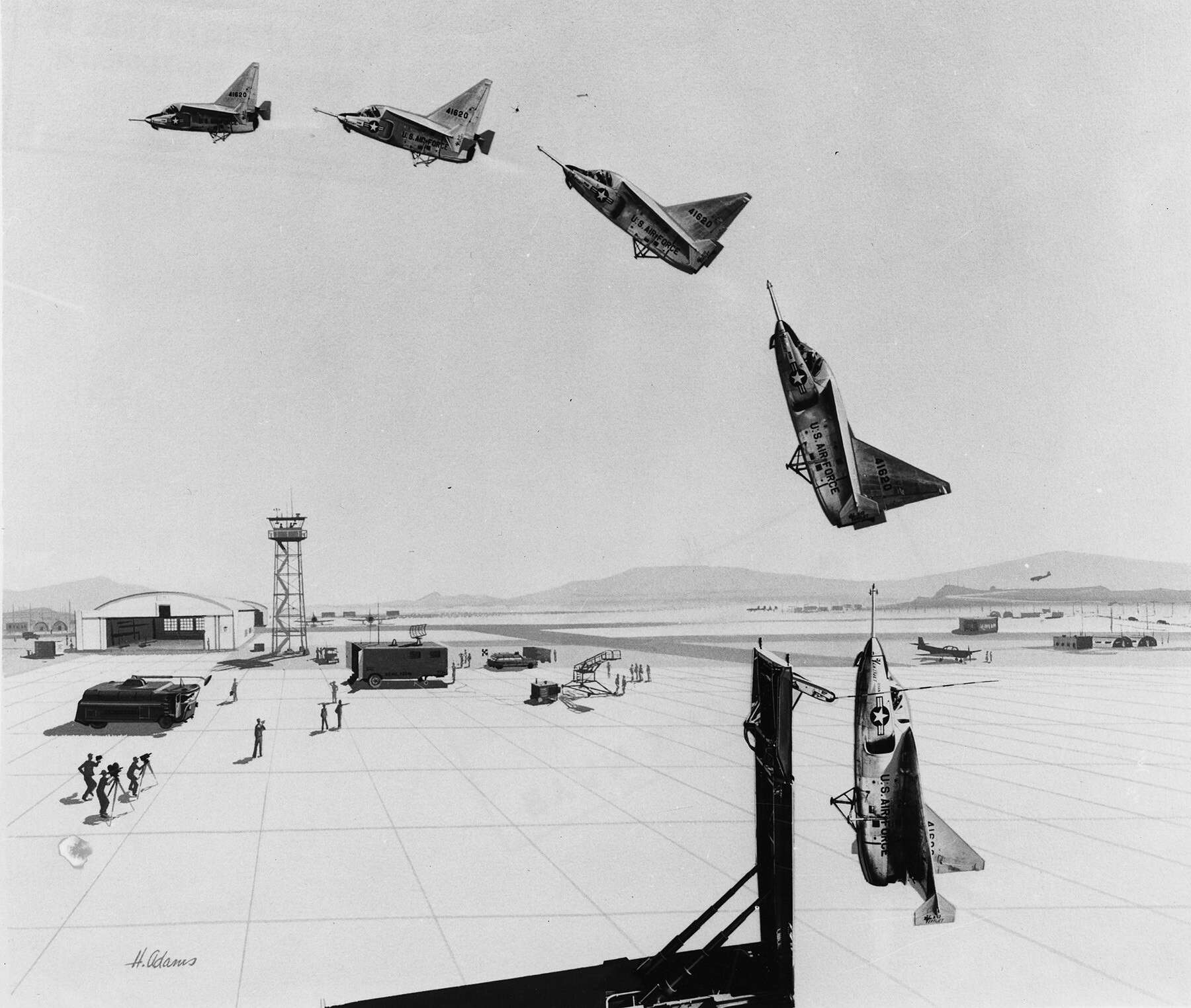
The earliest full-scale tail-sitter programs were the Convair XFY-1 “Pogo”, the Lockheed XFV-1, and the Ryan X-13 Vertijet, each motivated by military interest in point-defense fighters capable of operating from small clearings, forward bases, or naval platforms without runways. The XFY-1 demonstrated reliable vertical ascent and hover but proved exceptionally difficult to land because the pilot had to look rearward over his shoulder. The XFV-1 offered comparable vertical control with its cruciform tail and contra-rotating propellers, but the overall configuration never matured into a practical forward-flight aircraft. The X-13 Vertijet, powered by a small turbojet, achieved a complete transition from vertical to horizontal flight and back again. Yet, its limited payload and restricted operational capability kept it from advancing beyond the research stage.
These prototypes confirmed that vertical takeoff and landing were technically feasible, yet they also exposed the severe difficulties of transitioning between vertical and horizontal flight. As the aircraft pitched forward and the wings began to generate lift, the flow field changed abruptly: dynamic pressure rose, angles of attack fluctuated, and the wake curved around the airframe. Control surfaces had to operate in this unsteady environment with only marginal effectiveness, while the pilot, lying nearly supine with the cockpit facing upward, relied on limited visual cues. Because the aircraft were only marginally stable in vertical attitude, minor disturbances in roll or yaw could grow rapidly, requiring continuous corrective action that exceeded the capabilities of the available analog control augmentation.
Underlying aerodynamic and structural constraints further limited the practicality of these early tail-sitters. Hover performance depended strongly on disk loading: large propellers offered acceptable induced power requirements but still yielded short hover endurance and sensitivity to inflow disturbances, while jet-powered concepts suffered from extremely high disk loading and correspondingly high power and fuel consumption. Structurally, the airframe had to absorb landing loads along its longitudinal axis and maintain stiffness during transition, when aerodynamic and propulsive forces acted at unusual angles. These combined aerodynamic, control, and structural challenges ultimately prevented the early tail-sitter configurations from maturing into operational aircraft.
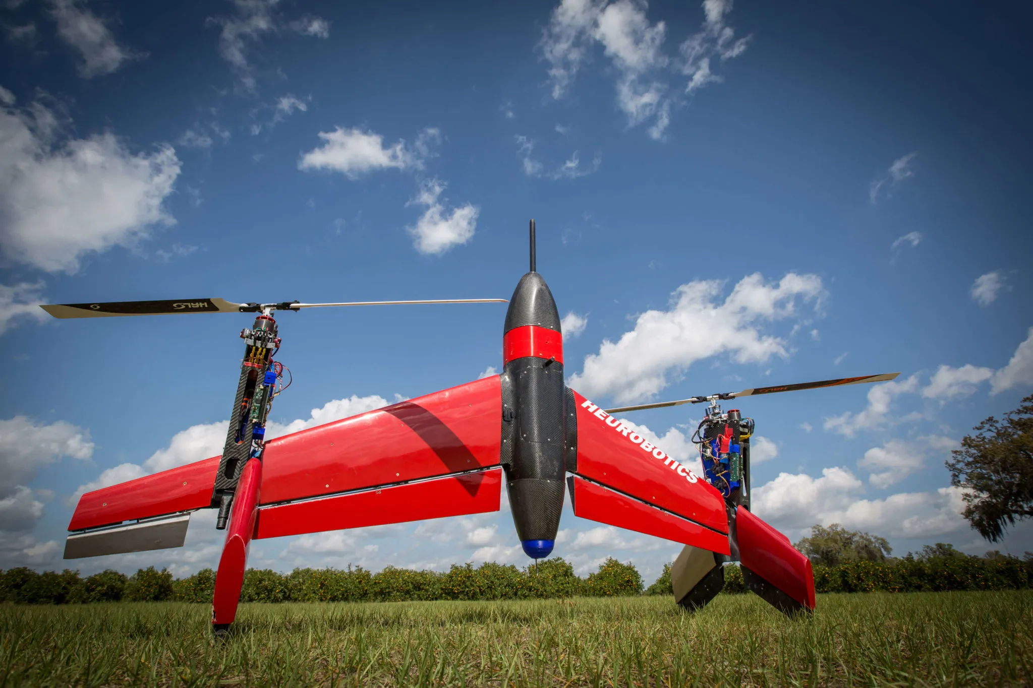
There is some renewed interest in tail-sitter aircraft today because of improvements in propulsion and flight controls rather than any change in the underlying aerodynamics. Electric motors can drive several propellers of modest diameter, helping keep effective disk loading at practical levels. Modern sensors and control systems also enable the aircraft to precisely regulate thrust and attitude during hover and during the transition to forward flight. These developments address many of the stability and handling problems that limited the early full-scale designs. A recent example of the tail-sitter approach is the design developed by Heurobotics. This aircraft used two rotors with independent collective pitch control to provide both vertical lift and forward thrust, thereby simplifying the transition to wing-borne flight. This design demonstrates how modern propulsion and control technologies can make the tail-sitter configuration practical for small-UAV operations.
Despite these technological advances, the aerodynamic fundamentals of tail sitters remain unchanged. Any tail-sitter, whether propeller-driven or jet-powered, derives its hovering efficiency directly from the area through which momentum is imparted to the air. Large propulsive disks produce lower induced velocities and lower power requirements, while small disks or high jet velocities produce high induced velocities and high fuel or energy consumption. These relationships continue to define the configuration’s performance limits. Modern electric tail-sitters are effective only because they are small and light, allowing disk loadings to remain modest, and because control augmentation mitigates piloting challenges.
Tiltrotors
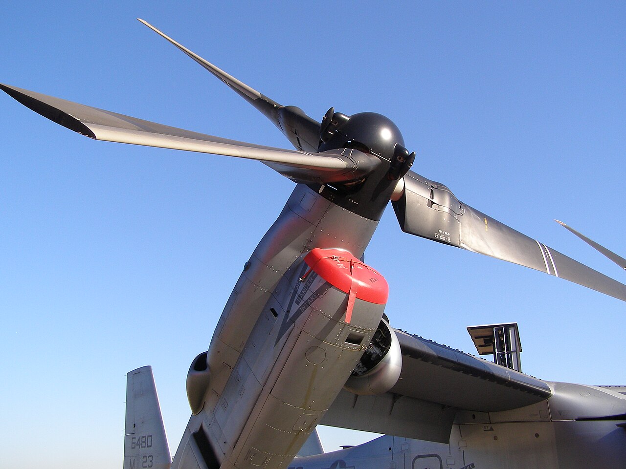
Tiltrotors are VTOL aircraft in which the propulsion system, consisting of large helicopter-like rotors called proprotors, can rotate between vertical and horizontal orientations. In vertical flight, the proprotors act as lifting rotors in the same manner as a helicopter, generating the thrust required for takeoff, hover, and low-speed maneuvering. In forward flight, the proprotors tilt forward and function as propellers, providing thrust to a fixed wing that carries the aircraft’s weight aerodynamically. The best-known example of this configuration is the V-22 Osprey, the first production tiltrotor.
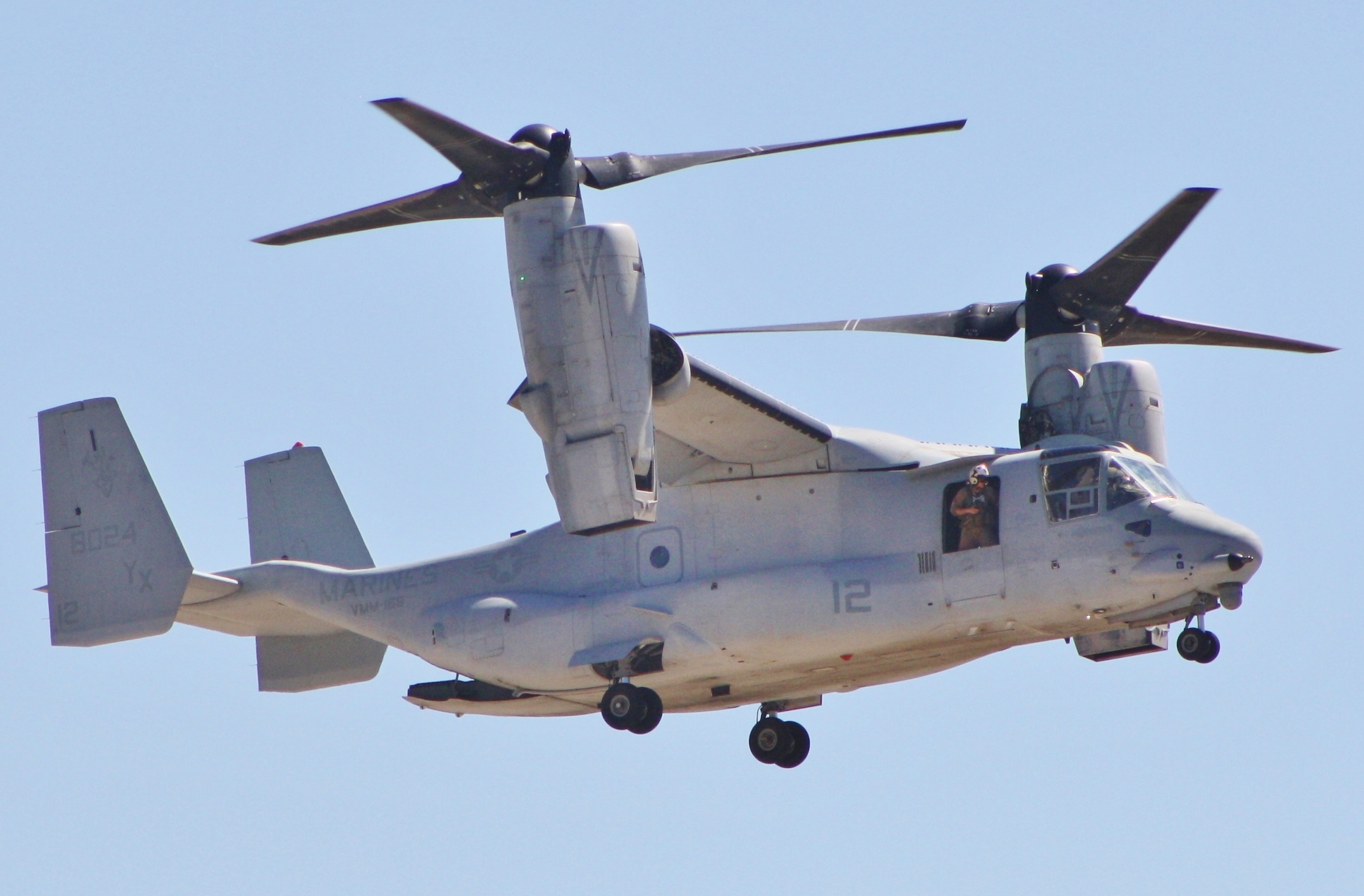
Tiltrotors were developed to combine the key advantages of helicopters and fixed-wing airplanes. From helicopters, they inherit runway-independent vertical lift, low-speed agility, and the ability to operate from confined or improvised landing zones. From airplanes, they gain high cruise speed, long range, and efficient wing-borne flight. This combination makes tiltrotors attractive for missions that require both vertical agility and rapid long-distance transit, such as special operations, long-range assault, disaster relief, and offshore logistics.
A defining feature of a tiltrotor is the tilting nacelle, which contains the engine, transmission, and proprotor. During takeoff, the nacelles are rotated upward so that the proprotors act as lifting rotors. After liftoff, the pilot progressively tilts the nacelles forward to transition the aircraft into wing-borne flight. During this conversion, the aircraft passes through a corridor in which both rotor-borne and wing-borne lift contribute to supporting the weight. The process requires careful coordination of attitude, airspeed, and nacelle angle to maintain stability and adequate control authority.
Although tiltrotors provide a compelling combination of VTOL capability and airplane-like cruise performance, they also introduce significant engineering challenges. The proprotors must operate efficiently in two very different flight regimes, hover and high-speed forward flight, which impose conflicting requirements on blade twist, solidity, airfoil design, structural stiffness, and tip speed. The airframe must accommodate large rotating systems, high hub loads, and complex gearboxes that transmit power between engines for one-engine-inoperative safety. These demands lead to a VTOL aircraft that is mechanically more complex and, on average, more expensive per unit weight than a conventional helicopter or a turboprop.
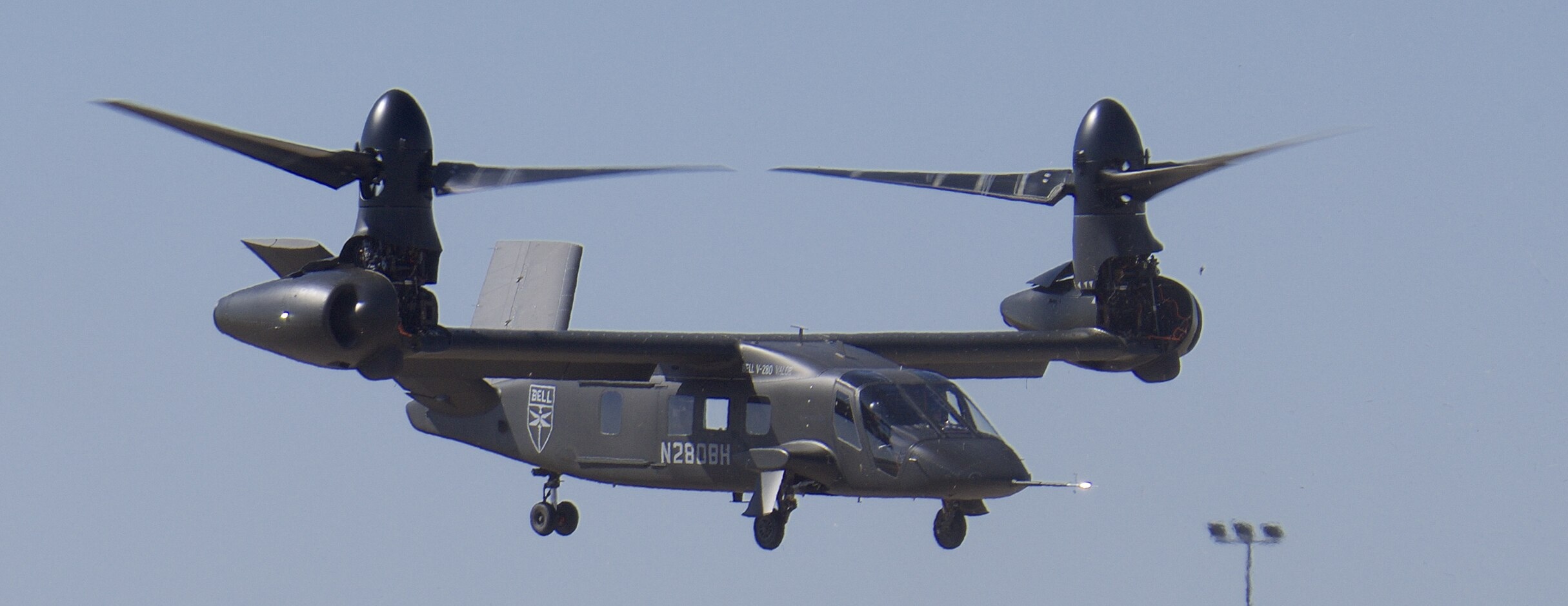
Beyond the V-22, newer designs such as the Bell V-280 Valor (see photograph below) aim to reduce mechanical complexity and improve efficiency through refined proprotor aerodynamics, lighter composite structures, and simplified tilt mechanisms. Several modern eVTOL concepts also use electrically powered tilting proprotors, taking advantage of distributed electric propulsion to avoid heavy mechanical transmissions while still enabling efficient wing-borne cruise.
Convertible rotorcraft continue to attract interest because they can bridge the gap between helicopters and fixed-wing transports. Their ability to carry meaningful payloads over long distances without runways is valuable for heavy-lift logistics, offshore operations, humanitarian relief, and expeditionary military missions where speed, flexibility, and access to unprepared landing zones are essential. These advantages come with higher acquisition and operating costs, since the aircraft must incorporate many of the systems and structural requirements of both helicopters and airplanes. As a result, the industry continues to explore convertible rotorcraft concepts that combine the vertical lift and hovering efficiency of helicopters with the speed and range of fixed-wing aircraft. Several configurations have been examined, including airliner-scale tiltrotors, often using one or two pairs of tilting proprotors that provide vertical lift in hover and propulsion in forward flight. Tiltwings and related configurations follow similar aerodynamic principles but differ in how the wing and propulsion system participate in the transition.
Tiltwings
Tiltwing aircraft achieve VTOL capability by rotating the entire wing and its propellers or proprotors from a near-vertical orientation for takeoff and landing to a horizontal orientation for forward flight. In the vertical mode, the rotated wing directs propeller thrust downward to generate lift. For cruise, the wing returns to a conventional attitude and carries the weight aerodynamically while the propellers supply forward thrust.
Historically, several experimental tiltwing aircraft demonstrated the feasibility of this approach, including the Vertol VZ-2, the Hiller X-18, the LTV XC-142, and the Canadair CL-84 “Dynavert.” These prototypes achieved controlled vertical takeoff, transition, and fixed-wing cruise, but none entered large-scale production because of mechanical complexity, transition workload, and crosswind sensitivity. The Hiller X-18 served as the first full-scale testbed for a tiltwing cargo aircraft and revealed key challenges in propeller control and transition stability, informing later programs such as the LTV XC-142.
Aerodynamically, the tiltwing concept offers substantial lift augmentation in STOL operation because the propeller slipstream remains aligned with the wing over a wide range of tilt angles. This blown-wing effect allows very high lift coefficients during takeoff and landing. The cost is that, in hover, the vertical wing lies directly in the rotor wake and free stream, producing complex unsteady flow on the fuselage and tail. During transition, the aircraft must pass through attitudes where the wing approaches stall and the tail surfaces encounter highly non-uniform flow, so adequate control authority is essential to maintain pitch, roll, and yaw stability.
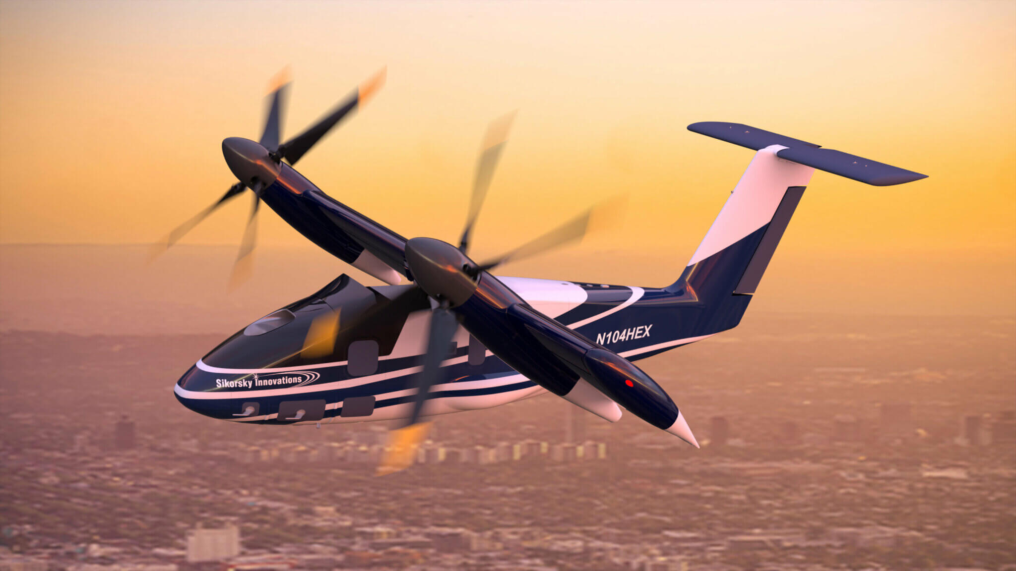
Modern studies and eVTOL concepts have renewed interest in tiltwings, especially when paired with electric or hybrid-electric propulsion. The Sikorsky HEX demonstrator illustrates this approach. HEX employs two large electric proprotors powered by a 1.2 MW turbogenerator to produce vertical lift at relatively low disk loading. As the wing tilts toward the horizontal, these proprotors transition to providing forward thrust while the wing takes over the lifting role. This architecture reduces some of the mechanical complexity of earlier tiltwing driveshaft systems but introduces challenges in hybrid-electric power integration, thermal management, and transition control laws.
Overall, tiltwing aircraft offer strong STOL and VTOL performance combined with efficient fixed-wing cruise. Still, they require careful management of aerodynamic loads during transition, robust control systems, and more complex mechanical arrangements than conventional helicopters or fixed-wing aircraft. Their practicality depends on whether specific mission advantages justify these added costs.
Proprotors
Proprotors are used on both tiltrotors and tiltwings. A proprotor is an aircraft propulsion system that serves two roles: it produces vertical lift in hover like a helicopter rotor and provides thrust in forward flight like a propeller. This dual requirement distinguishes it from conventional propellers, which are optimized solely for forward propulsion. Because it must perform effectively in both regimes, a proprotor’s diameter is typically larger than that of a propeller but smaller than that of a pure helicopter rotor, a compromise fundamental to its design. This arrangement enables convertible rotorcraft such as the V-22 Osprey to transition between vertical lift and forward flight using a single rotating system.
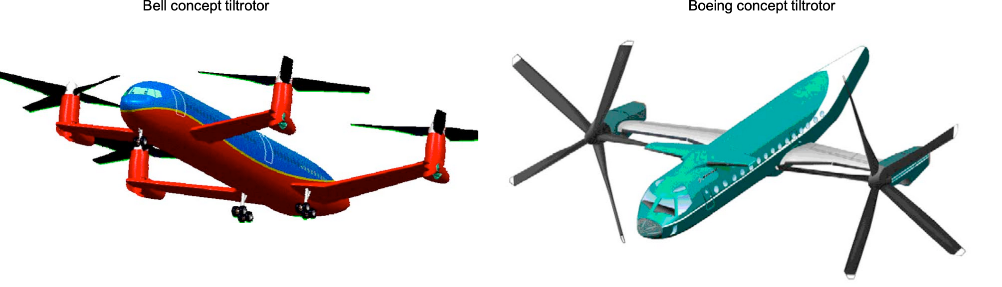
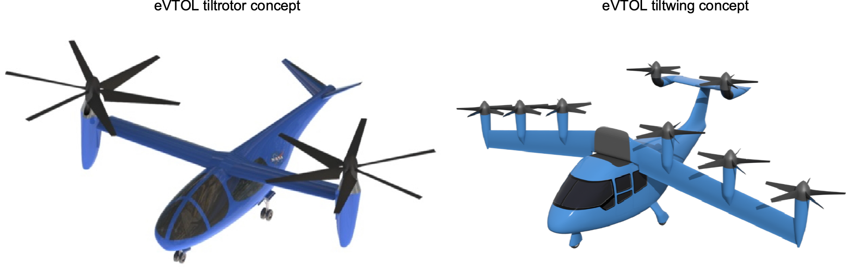
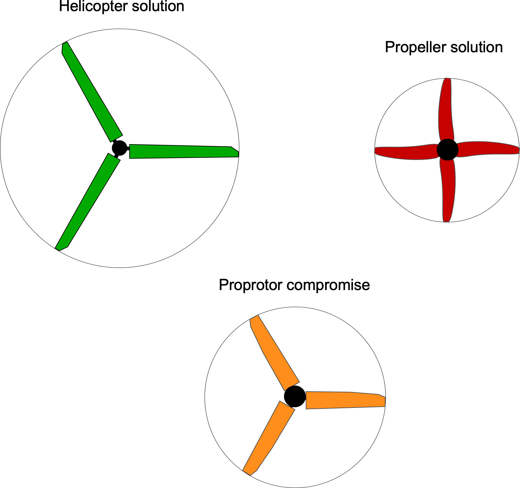
The performance of a proprotor depends on numerous blade-design and operational factors that must reconcile efficient hover with efficient forward propulsion. While some compromise is inevitable, the challenge is to balance these competing requirements without limiting the aircraft’s overall capabilities. This design balance is especially important for eVTOL rotorcraft, two proposed concepts being shown in the figure below, which rely heavily on high proprotor efficiency to maximize flight time on each battery charge.
Overall Design Challenges
A primary difficulty lies in designing proprotors that perform efficiently across a wide flight envelope encompassing diverse aerodynamic operating conditions. Unlike conventional helicopter rotors or propellers, which are optimized for specific situations, proprotors must maintain both good hovering efficiency and high-speed cruise performance. Addressing this dual requirement requires validated modeling tools that can predict rotor aerodynamic performance confidently across diverse operating conditions. At the very least, achieving hovering efficiency comparable to that of a helicopter while also attaining cruise efficiency approaching that of a typical turboprop-powered airplane will be fundamental to the success of a convertible rotor concept.
Operating State
Thrust, disk loading,  , (i.e., thrust per unit disk area), blade loading (thrust per unit blade area,
  ) or blade loading coefficient
  , and tip speed,
  , all affect the aerodynamic efficiency of a proprotor in both hovering and forward flight operations. In hover, the proprotors must carry the aircraft’s weight, i.e., for a pair of proprotors, each one will require a thrust equal to half the aircraft’s weight, i.e.,
  .
.
In forward flight, the proprotor encounters higher blade Mach numbers but operates at lower thrust levels because it must only overcome the aircraft’s drag, i.e.,
(42) 
where  is the aircraft’s lift-to-drag ratio at a given operational condition. The design compromise will be, in part, based on the required disk area and blade area. A larger disk area is better for hovering flight, while a lower blade area is needed for good propulsive efficiency, as illustrated in the figure below.
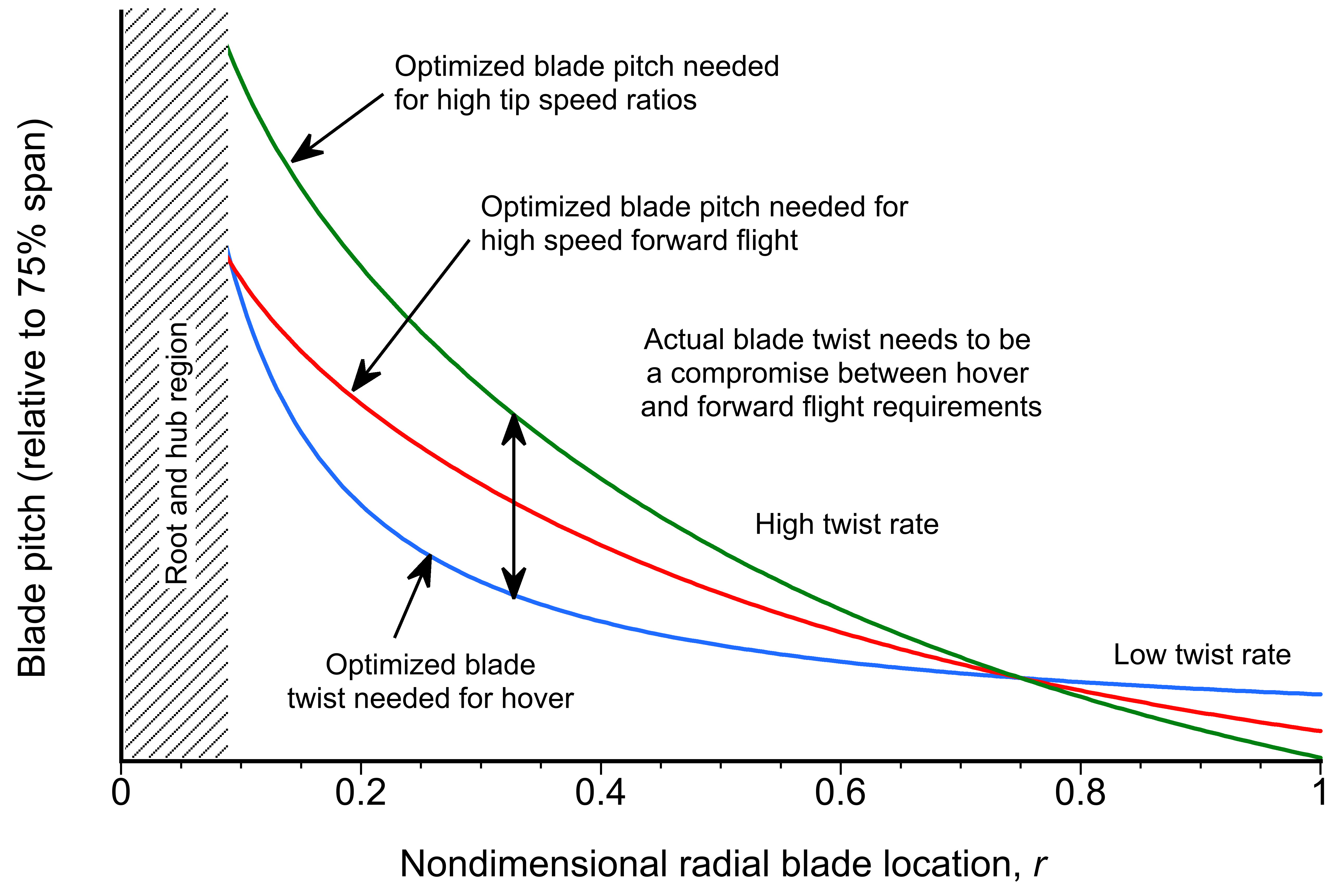
Blade Twist and Distribution
The blade twist required to maximize the hovering performance of a proprotor will not be the same as that needed to maximize the propulsive efficiency while retaining sufficient performance margins. As previously discussed, the twist distribution of a propeller blade is nominally hyperbolic, with less required twist for lower tip speed ratios[6] and hover. In practice, this compromise often results in a blade twist distribution that approximates the average of the optimal values for hover and cruise.
While in-flight blade morphing or twist adjustment is attractive for optimizing performance across flight regimes, current materials and actuation technologies are not yet mature enough for practical application. Smart materials, such as shape-memory alloys and piezoelectrics, show promise but face limitations in durability, actuation speed, and structural integrity under rotor loads. Integrating such systems without adding excessive weight or compromising safety remains a significant challenge. Consequently, proprotor designs rely on fixed-twist blades representing a carefully chosen compromise.
Solidity
Recall that the solidity of a rotating wing device is defined as
(43) 
where is the average (or weighted average) blade chord. Notice that the solidity is affected by the number of blades, . The value of the blade loading coefficient, , has an upper limit of approximately 0.14 when  is defined based on that for a helicopter rotor, i.e.,
(44) 
This limitation on the operating value of arises because of the maximum lift coefficient that the blade sections can realistically produce before stalling. Because of the need for sufficient stall margins for maneuvering flight and gusts in helicopter mode, the maximum value of should be no more than 0.10. This value imposes a lower limit on the proprotor’s solidity,  , for any given thrust coefficient , i.e.,
(45) 
Therefore, to generate a specified amount of thrust with the lowest power requirements and without the blades stalling inside its expected flight envelope, the proprotor must have a minimum blade area, , and a high enough tip speed, .
While induced losses dominate performance in hovering flight, which requires a low disk loading to achieve the maximum possible diameter for the proprotor, profile losses govern its propulsive efficiency, just as they do for a regular propeller. Therefore, a lower blade area will be needed for a proprotor when it operates as a propeller. However, this condition may not necessarily be achieved with a lower solidity because is inversely proportional to . Airfoils with good lift-to-drag ratios at the anticipated operating lift coefficients will also be needed to minimize profile losses. Therefore, the selected disk and blade areas, as well as perhaps the airfoil sections, must be a compromise between the two flight regimes. The selected solidity will also dictate blade and hub weights, which are critical for any VTOL concept.
Blade Planform
Proper optimization of the blade chord is needed to maximize the lift-to-drag ratios of the airfoils along the blade span at their anticipated lift coefficients and over their operational ranges of Mach and chord Reynolds numbers. To this end, an optimal combination of twist, taper, and airfoil shape will be needed. These design principles are the same as those for propellers and helicopter rotors, where a mild amount of taper from root to tip reduces profile drag and optimally distributes the angle of attack and lift coefficient over the blades. Thinning the blade will also be desirable, as it reduces the profile drag coefficient. However, the challenge is to use airfoils that are neither too thin to meet structural requirements nor so thick as to result in higher drag, higher divergence Mach numbers, higher pitching moments, or reduced maximum lift coefficients. Sweepback on the blade, as done with a modern propeller, may be needed to delay the onset of compressibility effects when the proprotor operates as a propeller.
Tip Speed
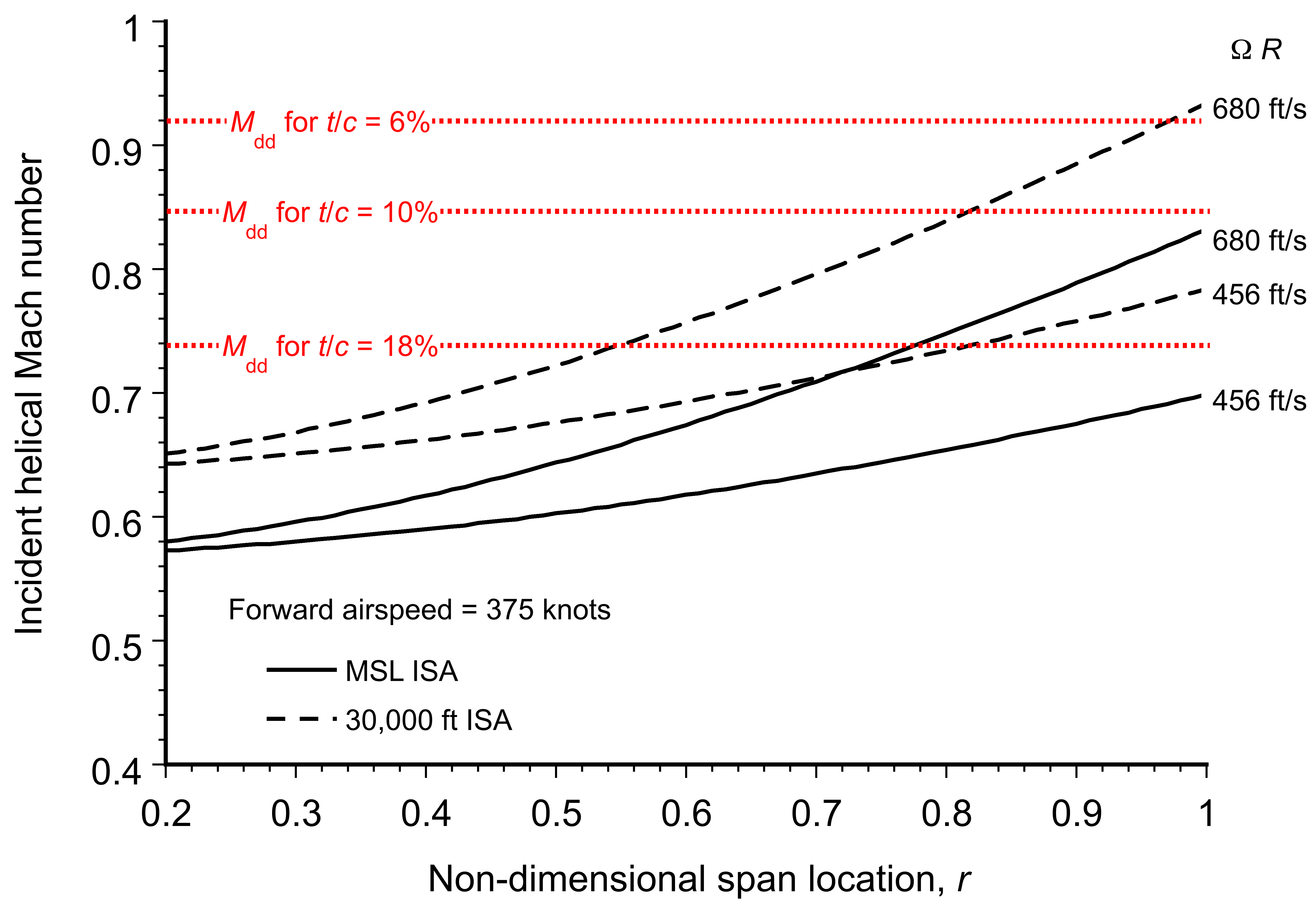
While higher tip speeds are desirable to maximize lift on the proprotor and to give good control authority with acceptable stall margins, reduced tip speeds in forward flight may be needed to ensure that the blades do not exceed the local drag divergence Mach numbers of the airfoils,  , to maintain propulsive efficiency. Thinning the airfoil section increases , as shown in the figure below. While lower tip speeds will reduce thrust and stall margins, they can also maintain efficiency by reducing the helical Mach numbers on blade sections below the drag-divergence Mach number.
While modulating tip speed has clear advantages, this assumes that stall or gust margins are not compromised and that aeroelastic stability will not become an issue. Future proprotor designs may benefit substantially by continuously optimizing the blade tip speed to produce the needed thrust while maximizing propulsive efficiency and maintaining acceptable performance margins.
Airfoil Sections
Appropriate airfoils with high aerodynamic efficiency in hovering flight, i.e., high lift-to-drag ratios at the design lift coefficients and high maximum lift coefficients, must be used on proprotors while retaining high drag divergence Mach numbers along the blade for forward flight. The figure below shows that the section thickness-to-chord ratio significantly affects the drag-divergence Mach number.
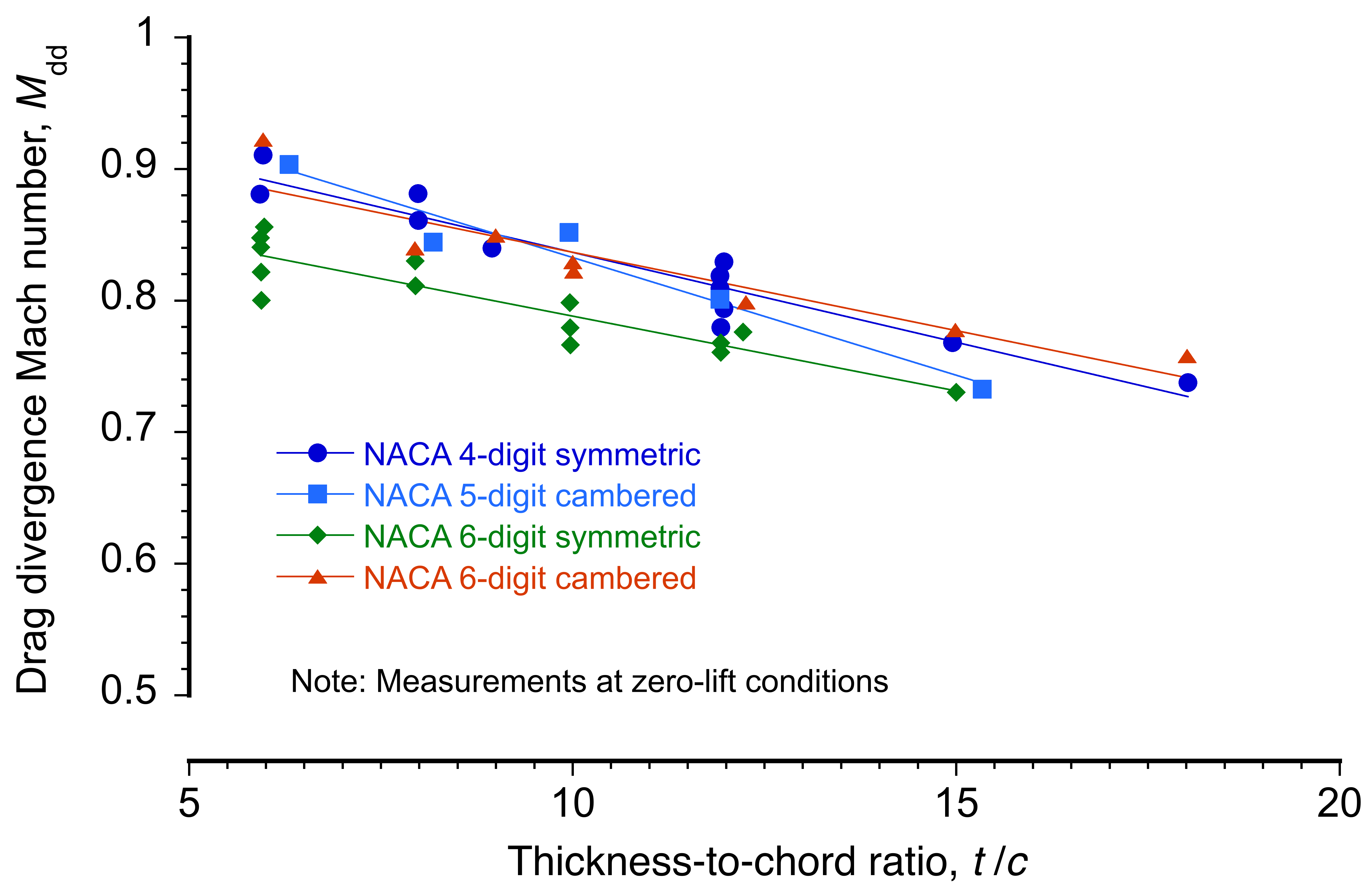
The aerodynamic diversity found on proprotor blades poses additional challenges in airfoil selection and/or design compared to those for helicopter rotors. In high-speed forward flight, more significant parts of the blades will operate at higher subsonic and transonic Mach numbers than in hovering flight. Profile power losses dominate proprotors at higher airspeeds, so accurate estimates of the onset of compressibility losses will be fundamental to predicting their anticipated performance and selecting the most appropriate airfoils.
The proprotor blades on the XV-15 experimental tiltrotor used NACA 64-series airfoil sections. These airfoils were designed for low drag at specific lift coefficients, primarily for subsonic applications. The “64” designation indicates that the airfoil maintains minimum pressure at 40% chord and is tailored for efficient performance within a limited range of lift coefficients. These airfoils are characterized by relatively thin profiles and extended laminar flow regions, making them ideal for proprotors. However, their efficiency comes at the cost of reduced tolerance to off-design conditions and potential sensitivity to surface contamination or roughness. The V-22 uses NASA XN-series airfoils (Experimental-NASA), which are considered proprietary.
In the future, the ability to fully integrate airfoil design methods (i.e., inverse design of an airfoil and blade shape to meet a given set of requirements) into the overall proprotor design may be needed to achieve the best proprotor efficiency over the broadest possible range of operating conditions.
Design for Hovering Flight
In hovering flight, the proprotors must support the entire weight of the aircraft plus an increment to counter the vertical download on the wings and airframe. While such download effects are relatively smaller on tiltwing concepts, for tiltrotors, this download can comprise a significant fraction of the rotorcraft’s weight. The requirement of a significant vertical force from the proprotor system demands the highest possible values of power loading if the resulting rotorcraft is to achieve good performance.
In hover, the power loading,  , is defined as the ratio of the thrust produced by the proprotor to the power required at the shaft to produce that thrust. The can be written in terms of the disk loading and figure of merit as
(46) 
where is the disk loading for any one of the proprotors. Power loading is a measure of absolute aerodynamic efficiency because it determines the propeller’s vertical thrust relative to the shaft power delivered, which can be correlated with the fuel expended, given knowledge of the engine’s brake-specific fuel consumption (BSFC).
Equation 46 shows that a high value of the figure of merit,  , is a necessary but insufficient condition to achieve efficient hovering flight. Low values of are also required to minimize the induced losses. However, using a large disk area on a proprotor will be incompatible with propulsive efficiency goals in forward flight, where induced losses are relatively small, thrust demands are much lower, and a lower solidity will be required to minimize the more dominant profile losses in this flight condition.
For a typical large-scale rotor system, the maximum achievable value of will typically be between 0.6 and 0.8. Suggestions have been made that proprotors are more efficient than helicopter rotors because they can reach relatively higher values of before stalling. However, Eq. 46 shows that such claims are misleading because proprotors typically operate at higher values of as a consequence of their design compromises. Therefore, even with marginally higher values, they will still operate at lower power loadings.
Using the figure of merit as a design metric requires further explanation, as its application is not without limitations. The figure of merit is defined relative to the datum “ideal” performance provided by the simple momentum theory, which can be written as
(47) 
where  (
( ) is an induced power factor that depends on the blade design (i.e., blade twist and planform, tip shape, and the number of blades) and proprotor operating state (i.e., thrust and disk loading), and
  represents the profile power losses, which depends primarily on airfoil section characteristics and planform shape. Through cumulative design improvements to the blade, profound impacts on overall hovering performance can be achieved.
However, a complicating factor in aerodynamic design is the number of interdependent factors that can influence the figure of merit. In particular, the attainable value of the figure of merit depends on the operating value of , which can be better exposed if the is rewritten as
(48) 
where , in this case, is the weight carried per proprotor (so that in hover  ). Theoretically, it can be shown that the best power loading of the proprotor is obtained when
  . However, this condition is generally achieved at values that are too low to be practical (i.e., the rotor size becomes unrealistically large). Therefore, a design goal will be to achieve the highest figure of merit by using the most appropriate blade shape at any value of and aircraft weight.
Considerable payoffs can result from minor improvements. Only a 1% increase in the value of may lead to a 2–3% increase in aircraft payload and perhaps a 5% increase in range, depending on the proprotor design and the rotorcraft’s anticipated mission(s). However, it is essential to recognize that the selection of disk loading, and ultimately the highest achievable figure of merit of the proprotor, may also be constrained by factors other than those related to its aerodynamics. Trades in the design space, driven by the need to attain specific values of propulsive efficiency in forward flight (for speed, cruise performance, and flight range), may also constrain the practical values of and . In this respect, power loading remains the most helpful metric for comparing different proprotor concepts because it provides an absolute measure of aerodynamic efficiency.
Design for Forward Flight
In forward flight, the wings of a convertible rotor aircraft carry its entire weight, and the proprotor operates as a pure propulsor, similar to a conventional propeller. Therefore, achieving excellent propulsive efficiency will be fundamental to achieving the highest flight speeds and maximizing payload and range. In forward flight, the proprotor operates at lower thrust but with higher inflow, and the induced losses become a progressively smaller fraction of the total power as the airspeed increases. The induced losses, however, will not be negligible, and the blade shape must still be carefully optimized to minimize them and achieve the highest efficiency. Furthermore, minimizing the fuel load requires that the proprotors be driven by engines with excellent specific fuel consumption. The airframe must also have excellent aerodynamic efficiency, with low drag, if the aircraft is to meet higher-speed and longer-range goals.
However, the highest levels of propulsive efficiency may not be attainable without compromising, to some extent, the ability to achieve low and high in hovering flight. Any significant compromise in hovering and/or propulsive efficiency will reduce the attainable flight range/, increase fuel requirements, and/or reduce payload. Overcoming this problem remains a significant design challenge. However, the compromises needed may not be severe if certain advances in aerodynamic capability can be realized and/or certain performance margins are relaxed.
Propulsive efficiency,  , can be defined in the same manner as conventional propellers, i.e.,
(49) 
where is the thrust produced by any one proprotor,  is the propulsive power,
  is the induced power, and is the profile power. The total power required can be written as
(50) 
where  , and
, and  is the propulsive (useful) power expended. According to the modified momentum theory for a rotor in axial flight, its induced velocity is
(51) 
which reduces to the correct result in the static thrust condition (i.e., hover) that
(52) 
Notice that in practice, will depend on . Furthermore, in the limit as becomes large, then  becomes increasingly small and approaches the limit
(53) 
Using Eq. 53, the efficiency can be rewritten as
(54) 
where it is apparent that the induced losses still depend on disk loading as they do in hover, but in this case, they diminish relatively quickly with increasing . It is apparent, therefore, that in high-speed forward flight, the efficiency of the proprotor is determined by the ratio of the relative profile power losses to the useful power expended; the equation for propulsive efficiency becomes
(55) 
Therefore, minimizing profile losses is critical if the goal is to maintain the highest propulsive efficiency at the highest airspeeds.
The net profile losses must be obtained by radial integration of the drag produced on each blade element, i.e.,
(56) 
where  is the resultant (helical) velocity at the blade element, i.e., the vector sum of the rotational and translational (airspeed) components. With some further assumptions, the profile power required with a given value of profile power coefficient
  can be shown to be approximately proportional to the cube of the helical tip speed of the blade, i.e.,
(57) 
where  is the helical tip velocity based on the vector sum of the rotational and axial flow components at the blade elements, i.e.,
  . The value of depends on a combination of proprotor solidity, planform shape, airfoil section(s), and their operating angles of attack, Mach numbers, etc. Unless stall becomes an issue, profile losses depend less on thrust because local lift coefficients along the blade vary from their design values. However, as previously explained, compressibility effects, as they contribute to , become significant when the local helical Mach number begins to approach the drag divergence Mach number(s) of the blade section(s).
The minimization of overall profile losses on the proprotor depends on the ability to design for a smaller disk area (i.e., a lower blade radius), a lower tip speed,  , and the lowest achievable value of
  at the operating lift coefficients. The primary challenge is to maximize the drag divergence Mach numbers and lift-to-drag ratios of the blade sections at appropriate combinations of helical Mach numbers and chord Reynolds numbers. The interdependent effects of Reynolds number and Mach number on airfoil performance depend on flight altitude. However, such effects are too airfoil-specific to be readily generalized.
Proprotor/Aircraft Performance Goals
It will now be apparent that achieving balanced hover and forward flight performance requires clearly defined proprotor design requirements. Multiple approaches may be necessary to determine the design requirements in relation to the desired mission performance. One approach is illustrated in the figure below, which compares the propulsive efficiency of a proprotor versus its hovering figure of merit. All things being equal, high values of both and will be necessary for good overall efficiency. However, because both and are only relative measures of efficiency, these parameters do not fully expose the requirements needed for the rotorcraft as a whole.
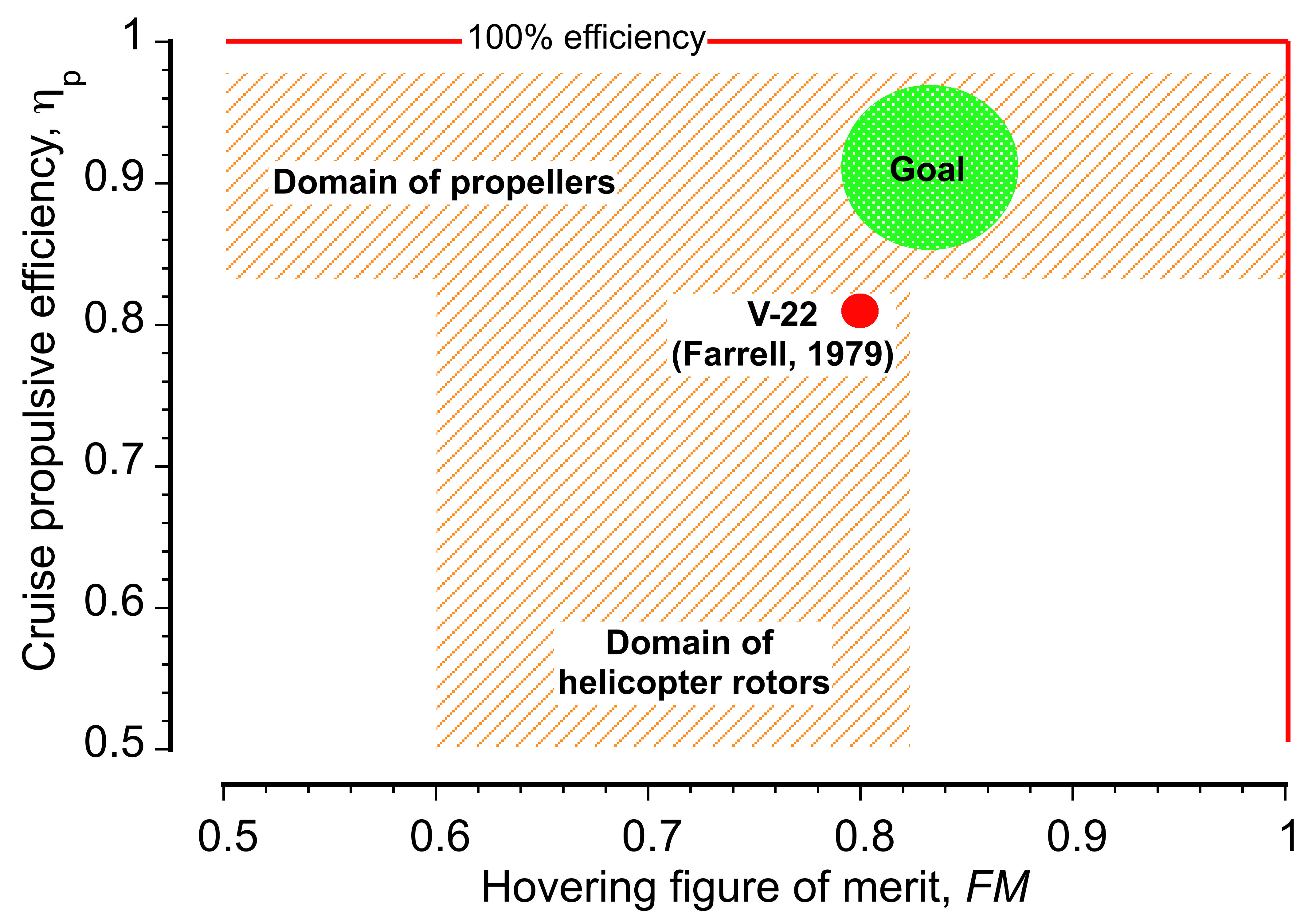
An alternative presentation in the figure below also summarizes a way to set proprotor efficiency goals [7] for future generations of convertible rotor aircraft in terms of hover power loading. Power loading, , is an absolute measure of hovering efficiency because it represents the ratio of thrust produced to the power required to produce that thrust, as well as fuel burn. Recall from Eq.47 that in hover
(58) 
so good hovering efficiency is only obtained by maximizing the figure of merit and minimizing disk loading. The requirements would be set at the density altitudes appropriate to the intended mission profile(s).
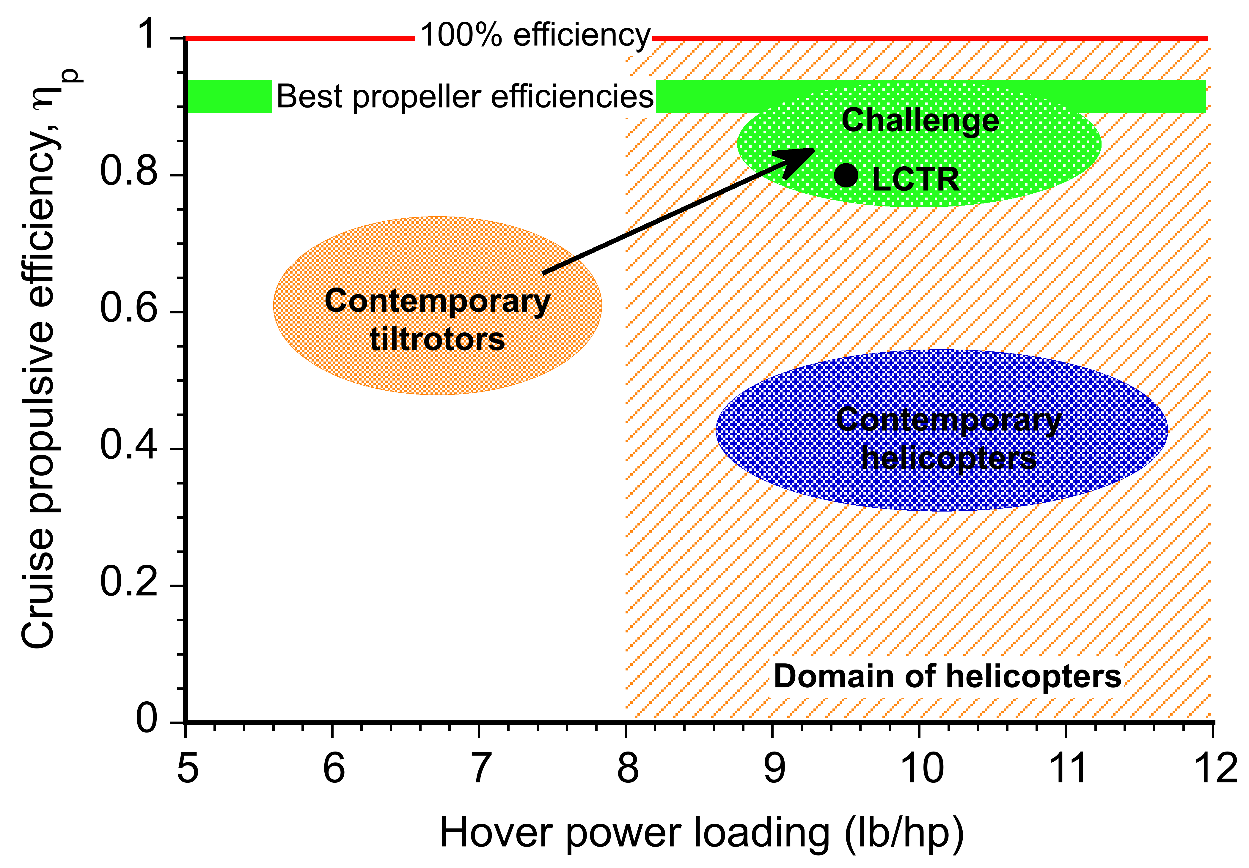
Conventional helicopters have hover power loadings in the range of 9 to 11 lb /hp (5.47 to 6.69 kg/kW). In contrast, current tiltrotors such as the V-22 (because of their smaller diameter rotors and higher disk loadings) have power loadings of only about 6 to 7 lb/hp (3.6 to 4.26 kg/kW), even with the claimed higher figure of merit (0.82) relative to a helicopter. Therefore, the design goal for any future convertible rotor concept is to approach the hovering power loading of a helicopter while also producing power loadings and propulsive efficiencies comparable to those of conventional propellers. As previously mentioned, this will require the judicious selection of the diameter, blade twist, planform, airfoils, tip shape, and tip speed of the proprotor.
Yet another presentation of proprotor design requirements is shown in the figure below in terms of the propulsive power loading in forward flight versus the power loading in hover. As previously mentioned, the currently flying tiltrotor, the V-22, has substantially lower power loading in hovering flight than a helicopter. So, it is only about half as efficient as a helicopter in hover per unit of payload. Recall also that the power loading in forward flight is
(59) 
which depends on both and  . The V-22 also has lower power loading in forward flight than a turboprop airplane. Based on its estimated , the V-22 can only be about half as efficient as a turboprop airplane in transporting payload. There is much scope for improvement from an engineering perspective.
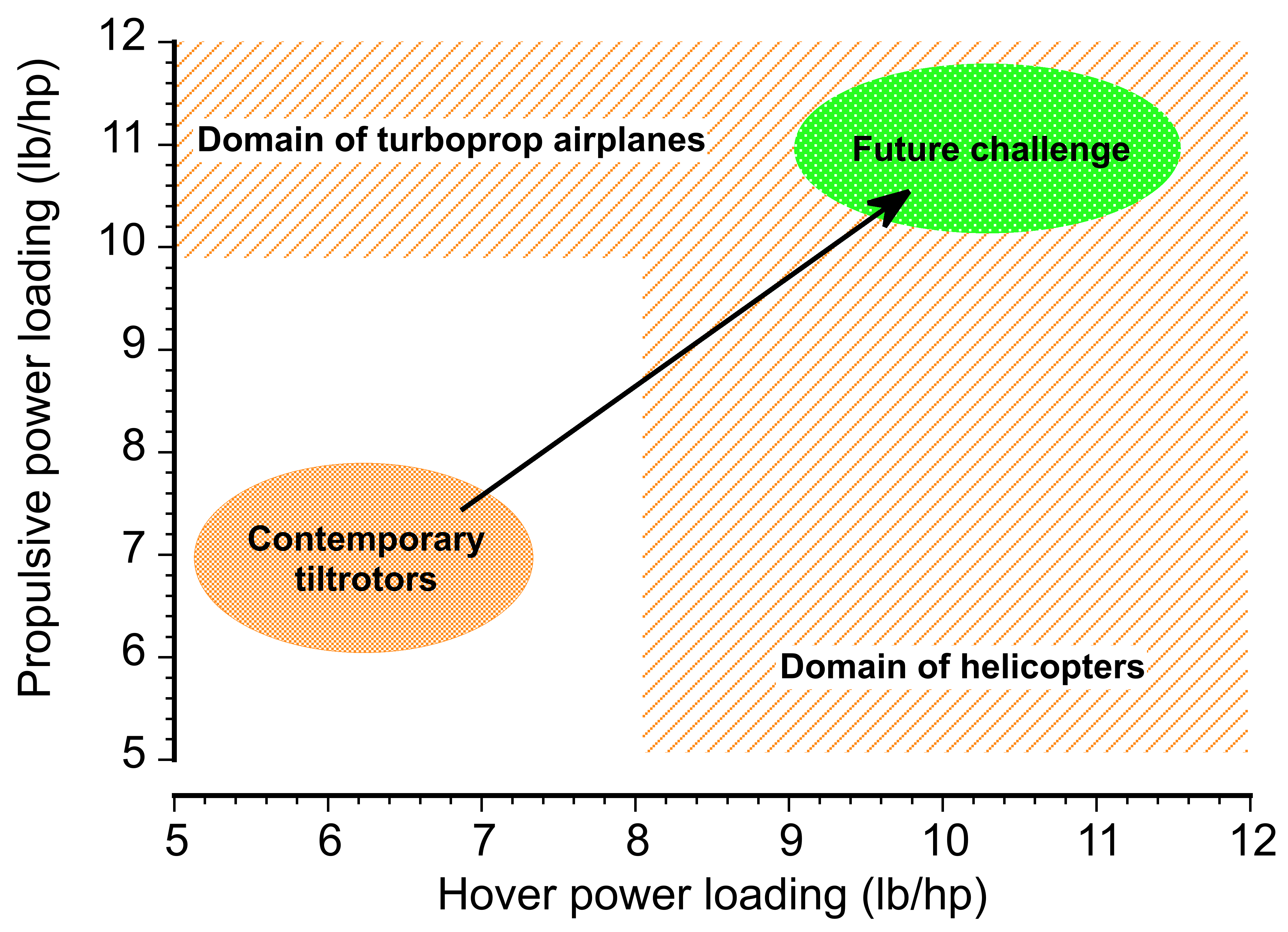
V/STOL & STOL Concepts
Short takeoff and landing (STOL) and vertical or short takeoff and landing (V/STOL) aircraft emerged from long efforts to reduce runway dependence while avoiding the high power requirements of pure vertical flight. Early work explored variable-incidence wings, large flaps, and stall-delay devices. Military needs in the 1940s and 1950s accelerated research into boundary-layer suction, jet flaps, deflected propeller slipstreams, and rotating wings. These approaches sought practical short-field performance without the sustained vertical thrust demanded of helicopter-type aircraft.
Blown Lift Systems
As the limits of VTOL power became clear, engineers turned toward concepts that retained some forward speed during takeoff. A modest ground roll allows the wing to carry part of the weight, sharply reducing induced drag and induced power. This idea produced a wide family of STOL and V/STOL designs using high-lift systems, propeller slipstreams, or engine exhaust to augment lift. Major research in the 1960s and 1970s led to the Boeing YC-14 and McDonnell Douglas YC-15, which demonstrated that upper-surface blowing could provide very high lift coefficients without vertical thrust. In this arrangement, over-wing engines blow exhaust over the flaps, and the Coandă effect bends the jet downward to generate large lift increments. These AMST prototypes were successful but were not fielded.
Within this broader family of runway-independent aircraft, blown-lift concepts use high-energy propulsor flow to energize the boundary layer and increase circulation over the wing. Other configurations, including tiltwings, vectored-thrust STOL fighters, and modern distributed-propulsion eSTOL aircraft, follow the same principle. Allowing the wing to produce even modest lift at low speed reduces vertical thrust requirements and lowers power demand.
The power required for vertical lift follows the momentum-theory relationship
(60) 
which increases steeply as weight increases or disk area decreases. A short takeoff run allows the wing to produce lift  , so the propulsion system must supply only
(61) 
and the lifting power scales as
(62) 
Even modest wing lift strongly reduces power demand. If the wing carries 25% of the weight, the induced power falls to about 58% of the pure-hover requirement.
STOL aircraft achieve short-field capability primarily by generating high lift coefficients at low speeds rather than by producing vertical thrust. The takeoff condition
(63) 
gives the liftoff speed
(64) 
Increasing  through slats, flaps (which may also increase ), slots, or blown surfaces reduces
  and takeoff distance. This is the classical STOL strategy used on the de Havilland Twin Otter, Helio Courier, and many modern eSTOL concepts.
Remember that pure VTOL demands very high power because the propulsion system must support the full aircraft weight at high disk loading. Using a short takeoff roll reduces induced velocity, lowers power and thermal stress, and increases safety margins during engine-out conditions. For these reasons, most operational VTOL aircraft, including the Harrier, F-35B, and V-22, use STOL procedures whenever possible. Emerging electric aircraft do the same to keep hover requirements within realistic energy limits.
Blown-lift systems occupy a middle ground between STOL and VTOL. They cannot hover, but they achieve exceptional low-speed performance and very short takeoff distances. Classic examples include upper-surface blowing, externally blown flaps, and circulation-control wings using tangential jets and the Coandă effect. Research aircraft such as the YC-14 and YC-15 achieved lift coefficients exceeding  , showing that aerodynamic augmentation can reduce runway length without incurring the power penalties of vertical lift. Modern distributed-propulsion eSTOL concepts extend these principles by blowing the wing more uniformly with multiple propulsors, providing high lift with good controllability at low speeds.
Short Takeoffs in a Harrier
Many VTOL aircraft can also operate effectively in the STOL mode. For example, the Harrier and F-35B regularly operate in STOL mode if a runway is available, which can boost useful load. The ski-jump takeoff ramp was introduced in the 1970s to improve the Harrier’s mission performance further when operating from aircraft carriers. The ramp imposes an upward rotation on the aircraft’s velocity vector at deck run-off, so that the initial flight-path angle is approximately equal to the ramp angle. Although the aircraft leaves the deck somewhat below the speed required for steady wing-borne flight, the upward component of velocity and the geometric height gained provide a short interval during which altitude can be maintained while the aircraft continues to accelerate.
During this transient “powered-ballistic” phase, the nozzles remain partially deflected, and the engine continues to add mechanical energy. The aircraft reaches the required wing-borne flying speed before the initial vertical velocity is exhausted, allowing a safe transition without descending below deck height. Flight trials demonstrated that this mechanism substantially reduced the required jet-borne thrust margin and allowed significantly higher takeoff weights. For this reason, the Royal Navy incorporated ski-jumps on its Invincible-class carriers, and the same principle is now used for modern STOVL aircraft such as the F-35B.
The analysis of the ski-jump takeoff is straightforward, but it involves several variables that can be adjusted based on each aircraft’s weight and mission. A conventional takeoff (CTO) from a long runway, as shown in the figure below, defines the reference maximum takeoff weight of the aircraft, denoted  . In this case, the thrust vector is aligned horizontally (nozzles are not deflected), and the aircraft accelerates until it reaches the required liftoff speed, i.e.,
(65) 
where  is the normal lift coefficient at rotation that allows for safe flight. With a long runway available, it is assumed that the aircraft can always reach
  and so can carry its full useful load of fuel and munitions.
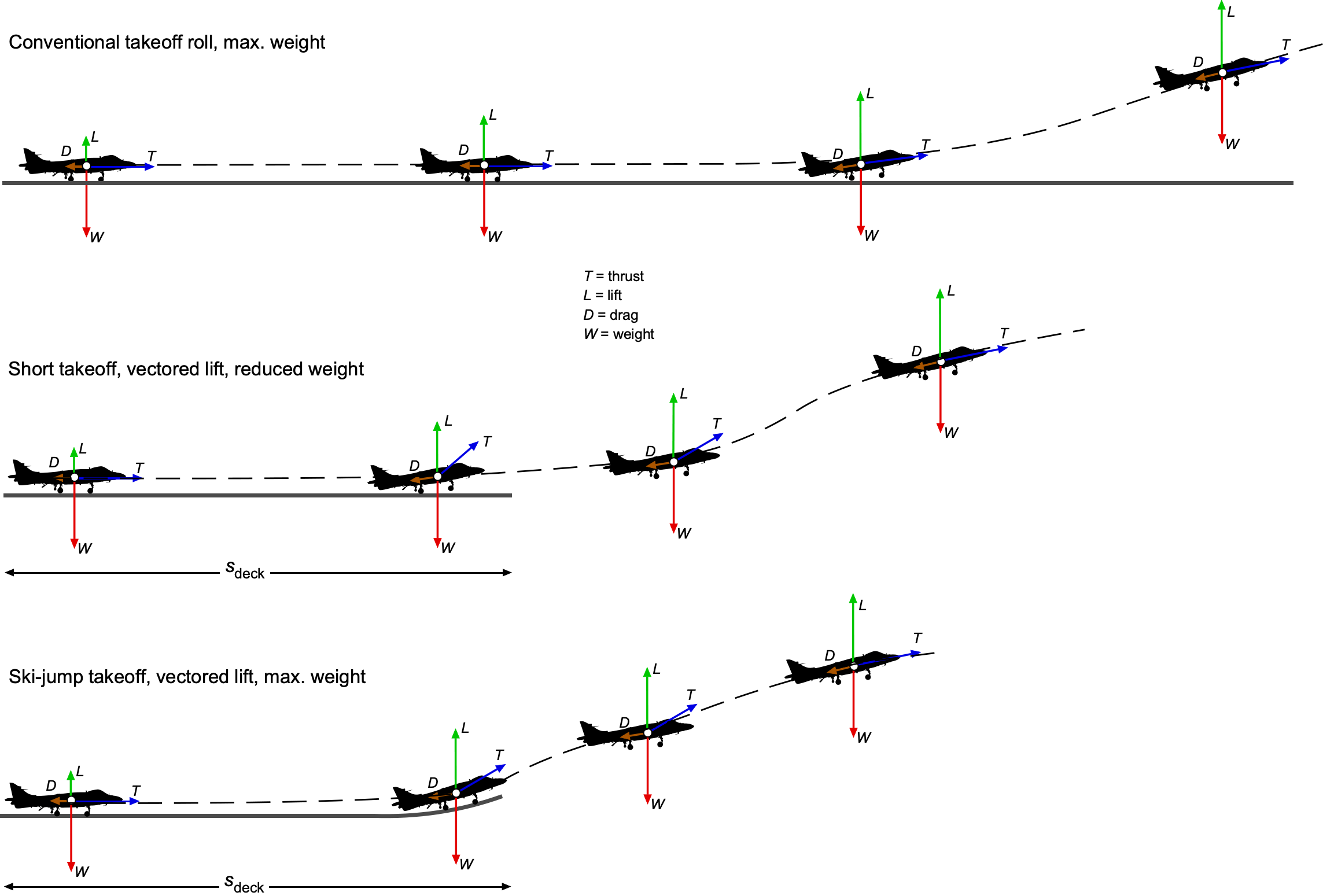
When operating from the deck of a ship with a relatively short allowable takeoff distance, the pilot can rotate the nozzles to provide both horizontal thrust and vertical lift. Let  be the nozzle angle measured from the horizontal, so that at any instant
(66) 
are the components of thrust parallel and normal to the deck, respectively. During the ground run, most of the acceleration is performed with relatively small so that the effective axial thrust is close to . A work-energy analysis with rolling resistance  , where
  is the coefficient of rolling resistance, then gives the end-of-deck speed as
(67) 
where  is an effective axial thrust that accounts for the actual nozzle schedule used by the pilot during the deck run. In practice, will be only slightly less than .
When the ship is underway, there will also be a wind-over-deck velocity,  , induced by the ship’s forward motion and the ambient wind. This velocity adds to the aircraft’s ground speed during the takeoff roll. If the ship’s heading is aligned with the takeoff direction, then the effective airspeed seen by the aircraft at the end of the deck is
(68) 
so the lift at the deck run-off becomes
(69) 
An increase in , therefore, increases  , which relaxes the requirement on both
  and
and  , and consequently allows a greater takeoff weight for the same ship and deck length.
At deck run-off on a flat deck, the flight-path angle is nearly zero, so there is no initial vertical climb velocity. To avoid an immediate descent toward the sea, the combination of wing lift and the component of vertical thrust to give an initial acceleration upward must satisfy
(70) 
where  is the nozzle angle at the bow of the ship and
(71) 
if  is assumed. Substituting this expression for into Eq. 70 gives an implicit relationship between deck length and the maximum takeoff weight that can be launched safely from a short flat deck, i.e.,
(72) 
Because  is short, and are limited, and the vertical condition in Eq. 70 can only be met by reducing the takeoff weight, i.e.,
(73) 
With a ski-jump fitted at the bow, the same thrust history  and nozzle schedule can be assumed to be used as for the short flat deck case. The ground run up to the foot of the ramp produces essentially the same speed given by Eq. 67. The key change is that the ramp rotates the velocity vector upward so that at the ramp exit, then
(74) 
and the aircraft has gained some altitude, say  , above the deck. At this instant, the vertical force is still
(75) 
but now the aircraft already has an angle of attack to generate wing lift, an upward velocity (rate of climb), and some initial altitude. The ramp, therefore, provides an initial vertical energy of
(76) 
which leads to a short ballistic segment after leaving the ramp. It is important to realize that the ski-jump adds no energy to the process, but alters the management of kinetic and potential energy. During this ballistic arc, the aircraft can climb or at least maintain altitude even if  is still slightly less than . While following this trajectory, the engine power continues to add mechanical energy according to
(77) 
so the airspeed  increases quickly until the wing lift and vertical thrust together are sufficient to support the aircraft’s full weight. In other words, the ski-jump gives the aircraft a ballistic trajectory until the airspeed is increased to the airplane’s full flying speed on the wing for that weight.
Because the aircraft now leaves the deck with upward velocity and some height, it no longer needs to satisfy the strict condition  exactly at the deck edge. Instead, a less restrictive instantaneous balance is sufficient to avoid contact with the sea, which may be represented generically as
(78) 
where the factor  captures the extra time and altitude provided by the ramp geometry. Using the same expression for as before (and again setting for simplicity), Eq. 78 gives the corresponding maximum takeoff weight that can be launched safely from the ski-jump, i.e.,
(79) 
Because  , Eq. 79 gives a larger solution than Eq. 72, so that
(80) 
Therefore, the recovered payload is
(81) 
and, for a sufficiently effective ramp and nozzle schedule, then
(82) 
The upshot of this analysis shows that a short flat deck forces a reduction in takeoff weight because the aircraft cannot reach the speed required for the combination of wing lift and vertical thrust to support the full weight at the end of the deck. A ski-jump rotates the velocity vector upward and adds height, producing a short ballistic trajectory while the nozzles are vectored, and the thrust continues to accelerate the aircraft. During this interval, the airspeed increases until the available wing lift plus vertical thrust can support the higher takeoff weight. In this way, the ski-jump recovers most or all of the payload that would otherwise be lost when operating from a short deck.
Drones & eVTOL
The recent emergence of electrically powered VTOL or eVTOL concepts for drones and Urban Air Mobility (UAM) has sparked renewed interest in VTOL technologies. These aircraft are envisioned as part of a safe and efficient low-altitude “air taxi” network capable of transporting passengers and cargo over short distances in urban and suburban environments. Whether such eVTOL aircraft can ultimately meet the required standards of performance, range, endurance, and airspace integration remains an open question. Public expectations have been strongly shaped by aggressive marketing, with many manufacturers promising quiet, efficient, zero-emission air taxis. In practice, the physics remain unforgiving. eVTOL flight still faces two fundamental barriers: the high power required to generate vertical lift and the low specific energy of contemporary battery technology. These constraints dominate both mission capability and economic viability.
Early multirotor drones, such as small quadcopters and similar unoccupied aerial vehicles (UAVs), first demonstrated the feasibility of distributed electric propulsion. Their success encouraged scaling these principles to piloted and autonomous air-taxi concepts. Companies such as Joby Aviation, Archer, and Vertical Aerospace are now developing full-scale eVTOL aircraft for the emerging UAM market. Modern eVTOL designs typically rely on multiple rotors or tiltrotor mechanisms to produce vertical lift before transitioning to wing-borne forward flight. Distributed propulsion allows thrust to be split among several smaller electric motors, improving redundancy compared with a single helicopter rotor. Many configurations incorporate fixed wings, with the rotors reorienting or offloading in cruise to achieve higher aerodynamic efficiency. Despite significant progress, the technical and operational challenges remain substantial, and widespread adoption will depend on demonstrating reliability, safety, endurance, and real-world economic value.
Performance
The biggest challenge in eVTOL development is energy storage for flight, as illustrated in the table below. Unlike airplanes powered by jet fuel or gasoline, which have high energy density (i.e., energy per unit mass), lithium-ion batteries give eVTOL aircraft much more limited range and endurance. A typical eVTOL requires high-capacity batteries with fast discharge rates and efficient power management to extend flight time.
| Power Source | Energy Density (Wh/kg) |
| Jet Fuel | 12,000 |
| Lithium-Ion Battery | 250–300 |
| Solid-State Battery | 400–600 (future) |
An eVTOL functions like a multi-rotor helicopter in hover, with each rotor contributing to the total thrust. The aircraft must generate enough thrust to balance its weight, i.e.,  . For an eVTOL with
  independent rotors, it can be assumed that the thrust is evenly distributed between the rotors, i.e.,
(83) 
where is the total weight of the vehicle. The total hover power can then be calculated using
(84) 
where  is the disk area of each rotor and is the rotor figure of merit in hover.
Analysis of an eVTOL
A simple analysis of a representative eVTOL configuration helps illustrate where these difficulties arise and why advertised mission capabilities are often unrealistic. Consider the energy requirements for a proposed 4-rotor, autonomous eVTOL configuration. The aircraft is a hybrid quad-rotor that uses four rotors for takeoff and two (tilting) for propulsion during wing-borne flight. To reduce energy consumption, many eVTOLs incorporate tiltrotor and various forms of lift-cruise designs. The manufacturer claims the following characteristics:
- Empty airframe mass (with motors and wiring) = 600 kg
- Estimated gross takeoff mass,
 kg
kg - Number of rotors,

- Rotor radius,
 m
m - Total mission duration: 45 minutes (
 min hover,
  min cruise)
 - Two passengers and baggage (150 kg each) = 300 kg
- The aircraft is either autonomous or flown remotely, so there is no physical pilot on board.
The total lifting thrust required in hover is
(85) 
The thrust per rotor (assuming equal sharing) is
(86) 
Using momentum theory, the hover power per rotor is
(87) 
The rotor disk area is  . With a figure of merit
  , the hover power per rotor becomes
  and the total hover power is
  .
.
An analysis of forward flight requires determining the aerodynamic drag in wing-borne cruise and the corresponding power. The drag consists of induced and parasite contributions. A representative wing area for an eVTOL of this size is  , giving a wing loading
(88) 
Assume an aspect ratio of  , a span efficiency of
  , and a realistic zero-lift drag coefficient of
  . The induced drag in level flight is
(89) 
and the parasite drag is
(90) 
Assume the aircraft cruises at a modest forward speed of  . Substituting the numerical values into the induced drag expression gives
(91) 
The parasite drag is
(92) 
The total drag is therefore
(93) 
If the propulsive efficiency of the forward rotors is  , then the cruise power requirement is
(94) 
Therefore, the total mission energy requirement is
(95) 
For  ,
,  , min, and min, then
(96) 
For a battery with an energy density of 0.25 kWh/kg, the required battery mass is
(97) 
so that  . When combined with an empty mass of 600 kg and passengers and baggage of 300 kg, the total becomes
  , which exceeds the manufacturer’s claimed gross takeoff mass of 1,200 kg, even before accounting for additional systems, structural margins, or reserve energy. Battery inefficiencies, thermal losses, motor losses, and required (mandated) operational reserves further reduce available energy. Only 70–80% of nominal battery capacity is typically usable, making the expected 35-minute cruise segment infeasible. A more realistic total flight time is closer to 20 minutes, which severely limits the utility of transportation.
To improve flight time and efficiency, next-generation eVTOLs will need higher energy-density batteries, such as solid-state or lithium-sulfur technologies, as well as hybrid-electric power systems, including hydrogen fuel cells. Innovations in solid-state batteries, rapid-charging systems, and low-drag airframe design will be crucial. Regenerative energy recovery systems may help capture energy during descent. Numerous challenges remain in improving energy density, infrastructure, and airspace integration. However, rapid progress in automation, fast-charging technology, and materials science may bring the promise of practical electric air taxis closer to reality.
Summary & Closure
This chapter of the eBook has examined the principal VTOL configurations that achieve vertical flight without using a helicopter. Although these aircraft vary significantly in appearance and engineering approach, they are unified by a common challenge: vertical lift must be generated by propulsion systems operating at relatively high effective disk loadings, which significantly increases the power required for flight and limits flight endurance. The various VTOL solutions explored over the past decades can be viewed as engineering strategies aimed at overcoming this fundamental constraint.
Jet-borne VTOL concepts offer compactness and a certain mechanical simplicity but are limited by poor hover efficiency and demanding flight-control requirements, especially during transitions. Tiltrotors and tiltwings achieve efficient wing-borne cruise by using large proprotors, although at the cost of significant mechanical and structural complexity, with systems common to both helicopters and airplanes. Ducted rotors offer a compact footprint and inherent blade shielding for safety and noise reduction, but they introduce additional drag and weight and increase sensitivity to off-design conditions. Lift-plus-cruise arrangements and multirotor electric VTOL designs prioritize redundancy and controllability, trading some airframe weight and aerodynamic efficiency for ease of operation and system robustness.
The historical progression illustrated by the V/STOL Wheel underscores that no single configuration solves the VTOL problem in all contexts. Successful designs emerge from carefully balancing hover performance, transition behavior, cruise efficiency, and mechanical complexity to meet the exact mission requirements. In this respect, there is no one-size-fits-all design solution. As new technologies such as electric propulsion, advanced materials, and modern flight control systems continue to mature, the design space for VTOL aircraft is expanding, yet the core aerodynamic and other engineering principles remain unchanged.
5-Question Self-Assessment Quickquiz
For Further Thought or Discussion
- Why have so few VTOL airplane concepts achieved operational success despite decades of experimentation, and which engineering constraints appear most fundamental?
- How does disk loading influence not only hover performance but also aircraft structure, noise, stability, and payload fraction?
- Modern electric propulsion removes many mechanical constraints present in historical V/STOL concepts. Does this meaningfully change the design space, or do classical aerodynamic limits still dominate?
- Tiltrotors and tiltwings address the transition problem differently. Under what mission conditions would one configuration be preferred over the other?
- Ducted fans offer safety and compactness but reduce cruise efficiency. For which applications does this trade-off become acceptable or advantageous?
- How might autonomous flight-control systems change the viability of configurations previously limited by pilot workload, such as tail-sitters or lift-jet aircraft?
- Are there emerging missions that might benefit from a VTOL configuration that historically performed poorly, such as urban air mobility, distributed logistics, or planetary exploration?
Other Useful Online Resources
For additional resources on VTOL aircraft, follow up on some of these online resources:
- The Vertical Flight Society is the primary professional organization dedicated to helicopter and VTOL technology and research. https://vtol.org
- Vertipedia is an online encyclopedia of historical and modern VTOL aircraft, concepts, and technologies. https://vertipedia.vtol.org/
- NASA’s Technical Reports Server provides open access to thousands of research papers on VTOL, rotorcraft, and propulsion. https://ntrs.nasa.gov
- NASA’s Aeromechanics Branch researches rotorcraft aerodynamics, dynamics, and vertical flight technologies. https://rotorcraft.arc.nasa.gov/Research/programs.html
- NASA’s Urban Air Mobility program provides resources on eVTOL development, certification challenges, and emerging flight technologies. https://rotorcraft.arc.nasa.gov/Research/Programs/UrbanAirMobility.html
- NASA’s historical overview of V/STOL technology is a concise technical review of jet-borne, propeller-driven, and hybrid VTOL concepts. NASA TM: Historical Overview of V/STOL Technology
- The FAA’s Advanced Air Mobility portal provides regulatory, certification, and integration information for new VTOL/eVTOL systems. https://www.faa.gov/regulations_policies/advanced_air_mobility
- Bell provides program information on the V-280 Valor, a next-generation tiltrotor representing modern advancements in proprotor technology. https://www.bellflight.com/products/bell-v-280
- Airbus publishes information on its CityAirbus NextGen and other eVTOL concepts aimed at future urban air mobility operations. https://www.airbus.com/en/innovation/zero-emission/urban-air-mobility
- Krüger, W., "Schubund Druckverhältnis bei Einbauten in Düsen," Lilienthal-Gesellschaft für Luftfahrtforschung, Bericht 141, 1949. ↵
- Kuchemann, D., & Weber, J., Aerodynamics of Propulsion, London: HMSO, 1953., ↵
- Mort, K. W., "Performance Characteristics of a 4-Foot-Diameter Ducted Fan at Zero Angle of Attack for Several Fan Blade Angles," NASA TN D-3122, 1965. ↵
- Mort, K. W., & Gamse, R. G., "A Wind-Tunnel Investigation of a 7-Foot-Diameter Ducted Propeller," NASA TN D-4142, 1967. ↵
- Lee, T. E., "Design and Performance of a Ducted Coaxial Rotor in Hover and Forward Flight," MS Thesis, University of Maryland, 2010. ↵
- Meaning lower values of
 . ↵
. ↵ - This form of presentation has been suggested by Dr. Kenneth Rosen, former VP of Engineering for Sikorsky Aircraft. ↵
