9 Aerospace Structures
Introduction[1]
Now that some understanding of the anatomy of flight vehicles has been gained, it is logical to examine their structural design characteristics in greater depth. While aerodynamics provides the foundation for atmospheric flight, an aircraft must also possess a suitably shaped structure capable of withstanding all imposed loads, whether aerodynamic, engine-induced, or those arising from the undercarriage during landing, including both vertical and side loads. Any aerospace structure must therefore be not only strong and lightweight, but also robust and durable. A clear understanding of the available structural design options and their inherent limitations is essential to achieving these objectives.
Many structural design goals and engineering challenges for spacecraft are similar to those for aircraft, particularly the need for optimally shaped structures made from high-strength, lightweight materials. However, spacecraft often require specialized materials capable of withstanding extreme thermal environments, especially during atmospheric re-entry when kinetic heating becomes severe. Likewise, supersonic aircraft may require structural features that enable controlled expansion under aerodynamic heating, thereby preventing the accumulation of excessive internal stresses.
Learning Objectives
- Appreciate the history and evolution of aerospace flight structures.
- Understand the primary loads on an airframe, such as tension, compression, bending, torsion, and shear.
- Know how aerospace structures are constructed, including spars, ribs, stringers, skin, etc.
- Be able to calculate the stresses and strains in elementary structures such as spars, struts, and trusses.
- Understand the principles behind the finite element method (FEM) and why it is used in designing structurally efficient aerospace structures.
- Be aware of the challenges in airframe design, including avoiding buckling and fatigue, and incorporating structural redundancy to enhance safety and reliability.
Brief History of Aerospace Structures
George Cayley, often referred to as the “Father of Aeronautics,” recognized the importance of constructing airplanes from lightweight materials. Cayley had the idea of using stacked wings in the form of biplanes and triplanes to give them a collective structural stiffness and strength. Otto Lilienthal built on Cayley’s ideas about flight and lightweight structures, designing several types of gliders that resembled the wings of birds and bats. Octave Chanute built gliders similar to Lilienthal’s, but incorporated external bracing wires to increase the wing’s structural strength and stiffness. In early 1903, Samuel Langley attempted to launch his tandem monoplane from a catapult, but it crashed after its frail wooden structure failed catastrophically.
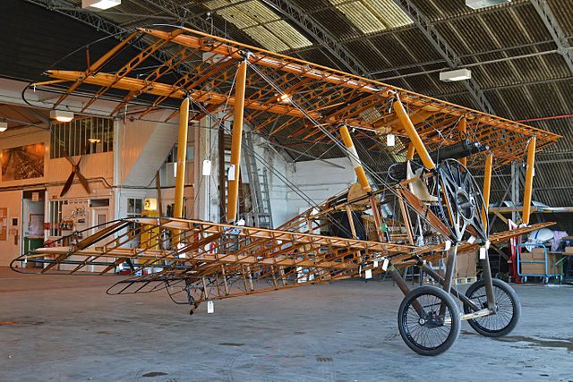
By the end of 1907, the Wright brothers had successfully flown several other versions of their original Flyer, a biplane type more strongly built from a wooden skeleton covered with fabric. Their wing design used spanwise spars and chordwise ribs braced with struts and wires. The main advantage of the biplane is that its upper and lower wings are connected by vertical struts and bracing wires, forming a strong, box-like structure, as shown in the photograph below. This type of design is much more resistant to bending and twisting than a single wooden wing. The skeleton is then covered in cotton fabric, which is tightened and sealed by brushing on cellulose dope. However, a biplane wing design also has high aerodynamic drag, which is a significant overall disadvantage. Nevertheless, this type of wing-and-airframe construction continued into the 1930s, and many successful biplane and triplane aircraft were built.
In 1909, Louis Bleriot of France built and flew a monoplane aircraft made of wood and fabric, although it was extremely fragile. One significant advantage of a monoplane is its reduced aerodynamic drag compared to the braced wings of biplanes or triplanes. Bleriot followed Octave Chanute‘s approach, where steel wires supported the single wings from a tall mast extending above the fuselage. However, the cables still created significant aerodynamic drag on the airplane, reducing its performance. Bleriot also used a welded truss-type fuselage that was lightweight yet strong, and this method became a standard for early airframe construction.
By the 1920s, aluminum alloys suitable for airplane construction had become increasingly available, so airplanes made of wood and fabric were being increasingly relegated to history. In addition, the years leading up to WWII saw many advances in aircraft construction, and riveted aluminum “stressed skin” construction became the standard for almost all new aircraft. In 1925, Ford Motor Co. entered the aviation business with the 4-AT Trimotor, a three-engine, all-metal airplane using corrugated aluminum skins. Dubbed “The Tin Goose,” it quickly became successful and was used by over 100 airlines worldwide.
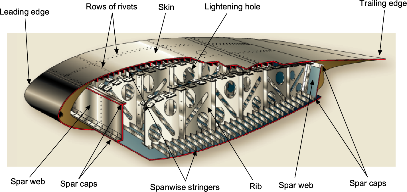
By the mid-1930s, airplanes were becoming larger and heavier, and were almost entirely made of stressed-skin aluminum construction, with components riveted together. Other construction methods were developed to achieve the required structural strength and stiffness of the wings, including multi-spar and box-beam designs, one of which is illustrated in the figure below. Box beam designs use multiple spar caps, webs, and shear panels to achieve high bending and torsional stiffness, efficient material use, and overall structural redundancy.
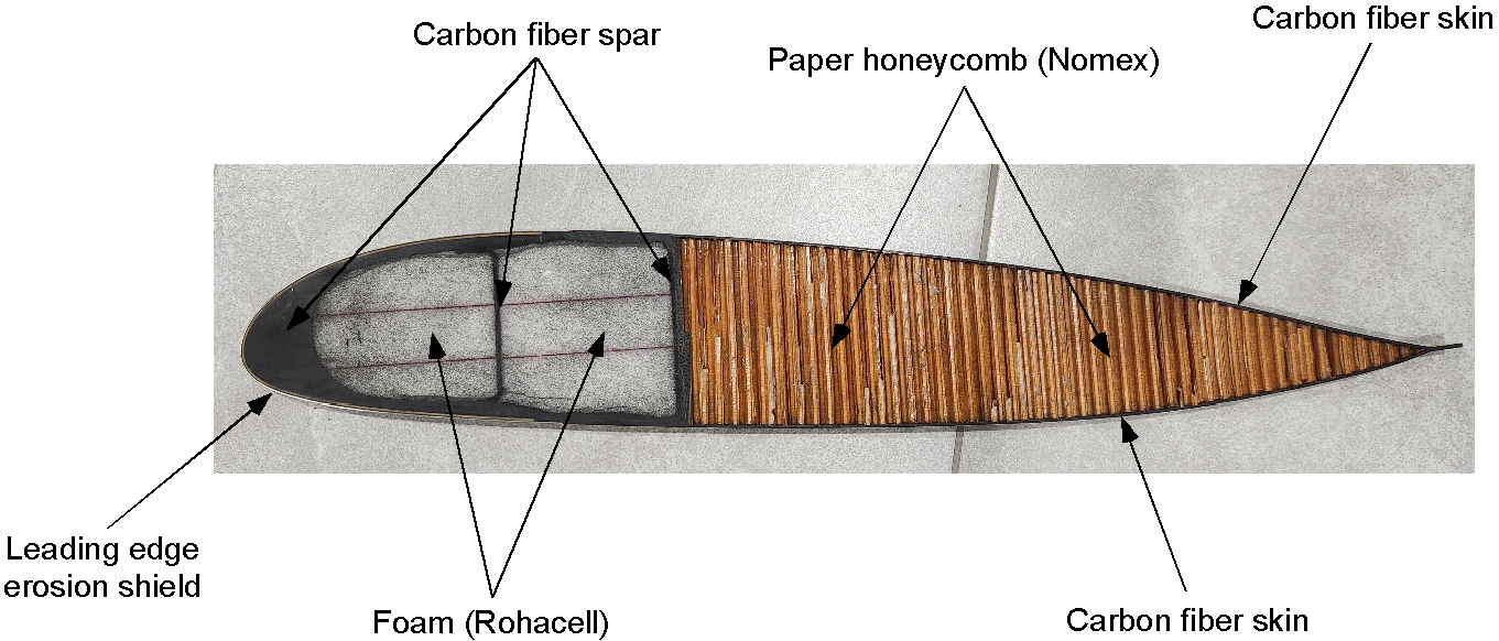
Over the last 50 years, there has been a steady increase in the use of honeycomb and foam-core sandwich components made from composite materials such as glass and carbon fiber. Bonded aluminum honeycomb sandwich panels, developed in the 1960s, offer exceptional stiffness and strength for their weight. These sandwich structures were increasingly used for wing skins, flight control surfaces, cabin floors, launch vehicles, satellites, propeller blades, and many other applications. Sandwich construction is widely used in the manufacturing of helicopter rotor blades, as illustrated in the figure below. The rotor blades must be extremely strong but also lightweight. The dominant loads on the blade are centrifugal forces from its rotation, which produce a tensile load along its length. The blades are also subjected to cyclic lift forces that cause bending and torsional twisting. Early rotor blades were made of aluminum or steel, perhaps using metal honeycomb as a core material.
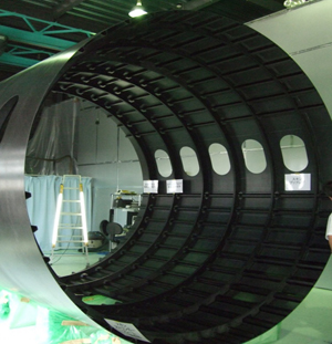
Over the last few decades, advanced materials and manufacturing techniques have enabled a transition from primarily building airframe structures made entirely of aluminum to structures composed primarily of composites, such as carbon fiber-reinforced polymer (CFRP). CFRP offers several advantages over traditional aluminum. Its higher strength-to-weight ratio means that structures made from CFRP can achieve the same or greater strength while using less material. This reduction in material volume lightens the overall structure, improving fuel efficiency per unit of payload. For example, the fuselage barrel shown in the photograph below is approximately 30% lighter than it would be if made using aluminum stressed-skin construction.
Modern aerospace structures can be tailored using advanced computational techniques, such as the finite element method (FEM). FEM enables engineers to simulate and analyze the structural performance of complex shapes and materials under various conditions. This tailoring ensures that every component is optimized for maximum structural efficiency, balancing strength, stiffness, and weight. Additionally, CFRP’s resistance to fatigue and corrosion, combined with its superior mechanical properties, yields a longer service life and lower maintenance costs compared to traditional materials. Consequently, the shift toward composites, such as carbon fiber-reinforced polymer (CFRP), in aerospace engineering represents a significant leap toward lighter, stronger, and more efficient airframes that meet the stringent demands of modern aviation.
The history of spacecraft structures spans from the simple stainless steel shells of early satellites to the complex modular designs of the International Space Station (ISS). Key milestones include the Apollo Lunar Module’s lightweight aluminum and titanium construction, as well as the Space Shuttle’s intricate aluminum airframe, which is covered with reinforced carbon-carbon tiles. Modern 3D-printed and inflatable structures enable cost-effective, adaptable designs. At the same time, projects like SpaceX’s Starship push boundaries by utilizing lightweight stainless-steel structures, embodying the continuous evolution of spacecraft structures in response to technological advancements and evolving exploration goals.
Types of Structural Loads & Stresses
The aerodynamic and other loads or forces imposed on a flight vehicle cause internal stresses in the material(s) from which the flight vehicle is made. Stress is the internal force that opposes the deformation of a material under load. The corresponding deformation of the material under load is referred to as strain. Therefore, when any material is subjected to an external loading, it will become stressed and deformed, i.e., it will always exhibit some strain, regardless of how stiff or strong the material is.
As shown in the figure below, five types of stress and strain can occur in the parts of aerospace structures: compression (pushing or squeezing), tension (pulling), shear, torsion (twisting), and bending. These stresses and strains can be produced individually in a structural component or in combination with other loads.

The five basic types of stresses and strains that can be produced in aircraft structures are compression, tension, shear, torsion, and bending.
- Compression is the stress that causes a strain, squeezing and shortening the part. A component’s compressive stiffness is its resistance to compression forces.
- Tension is the stress that resists the force pulling and causes a strain that tries to extend the part. A component’s tensile stiffness is its resistance to tensile forces.
- Shear is the stress that resists the forces acting in opposition, tending to cause one material layer to move relative to the adjacent layer. For example, most fasteners used in aerospace structures are subjected to shear.
- Torsion is the stress produced by torque that causes a strain, resulting in a twisting effect. Torque is a moment, so it is the product of a force and a distance, or “arm.” Therefore, a component’s torsional stiffness is its resistance to twisting.
- Bending stresses result from a combination of compression and tension in the material. A beam-like spar or other component subjected to a bending moment will cause a compressive strain on one side and a stretching strain on the other. In most cases, the individual structural members of aerospace structures are designed to carry mostly tension or compression rather than pure bending.
Structural Stress & Strain Relationships
Stress, given the symbol  , is used as a measure of the forces that cause a structure to deform and can be defined as the force per unit area acting on the cross-sectional area of the structure, i.e.,
(1) 
where  is the force, and
  is the area of the cross-section over which the force acts. Stress has units of force per unit area, which is analogous to the internal pressure of a structure. A force pulling on a structural member causes it to elongate, creating tensile stress. A force squeezing a member is called compressive stress. A structure subjected to forces from all sides is said to be under bulk stress.
Strain, given the symbol  (or sometimes
  ), is a measure of the deformation of an object under such stress and is defined as the fractional change of the object’s length relative to its original length, i.e.,
(2) 
where  is the original length and
  is the change in length. Notice that strain is a dimensionless quantity.
The stress produced in a structural member also depends on the stiffness of the material used for that member. Many materials exhibit a linear elastic relationship between stress and strain, as shown in the figure below, at least up to the proportional limit, indicated by the dashed line. Beyond this point, the strain in the material is so great that its properties change, and it will eventually break.
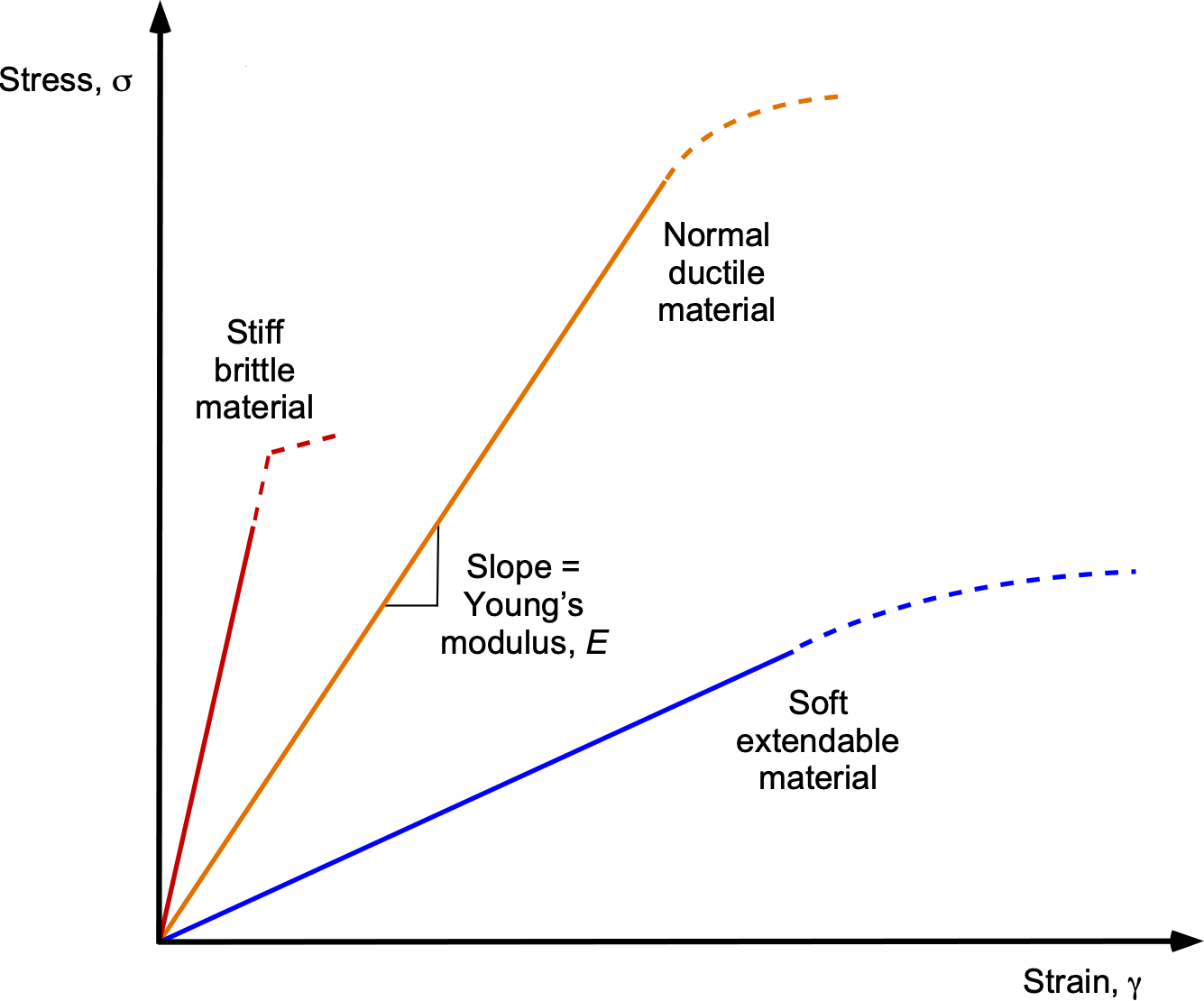
The elastic nature of materials means that after the load is removed and the stress is released, the material returns to its original undeformed state. This linear stress-strain relationship is known as Hooke’s Law, and the gradient or slope of the stress-strain curve is called the modulus of elasticity, given the symbol  , which is usually called Young’s modulus, i.e.,
(3) 
Stiff materials have a higher Young’s modulus value but tend to be brittle, fracturing easily. Soft, easily extendable materials have lower Young’s moduli.
Check Your Understanding #1 – Determining stress & strain in a structural member
A structural member in an airframe has a cross-sectional area of 3.2 cm2 and a length of 1.3 m. A tensile force of 0.51 kN is applied to the member, causing it to elongate by 0.21 mm. Assuming the material is perfectly elastic, determine the stress and strain in the member.
Show solution/hide solution.
The stress is given by
![\[ \sigma = \frac{F}{A_c} \]](https://eaglepubs.erau.edu/app/uploads/quicklatex/quicklatex.com-a222486a2efc78dbad1836d4bd87a317_l3.svg "Rendered by QuickLaTeX.com")
where is the force, and is the area of the cross-section. Inserting the known values for this problem gives
![\[ \sigma = \frac{F}{A_c} = \frac{0.51 \times 10^3}{3.2\times 10^{-4}} = .594~\mbox{MN m$^{-2}$} = 1.594~\mbox{MPa} \]](https://eaglepubs.erau.edu/app/uploads/quicklatex/quicklatex.com-f16f23b859f5ea72541cad97ce728f94_l3.svg "Rendered by QuickLaTeX.com")
Note that stress is measured in units of Pascals (Pa) in SI units, i.e., 1 N m = 1 Pa. The corresponding strain is defined as
![\[ \gamma \equiv \epsilon = \frac{\Delta L}{L} \]](https://eaglepubs.erau.edu/app/uploads/quicklatex/quicklatex.com-152be9eec5d9c4b2af29bdee7092d1d8_l3.svg "Rendered by QuickLaTeX.com")
Inserting the known values gives
![\[ \gamma \equiv \epsilon = \frac{\Delta L}{L} = \frac{0.21 \times 10^{-3}}{1.3} = 0.000162 \]](https://eaglepubs.erau.edu/app/uploads/quicklatex/quicklatex.com-9c8df3d8235566e7273fa0b4fd8d00be_l3.svg "Rendered by QuickLaTeX.com")
Notice that strain is dimensionless (i.e., it has no units).
Trusses & Shear Webs
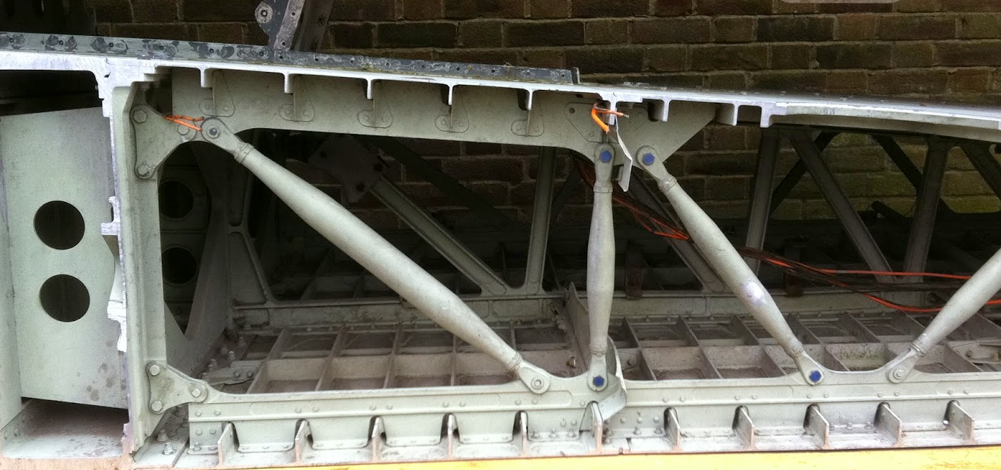
The development of aircraft structural concepts paralleled advances in aerodynamics, materials, and flight performance. In the earliest aircraft, such as the Wright Flyer and many WWI biplanes, a significant portion of the airframe consisted of trusses made from rods and cables, as illustrated in the figure below. These frameworks consisted of a series of triangular elements, typically constructed from wood or steel tubes, with tensioned wires providing bracing and contributing to the structural stiffness. By appropriately combining rods and wires, designers achieved a lightweight and mechanically efficient structure. A fabric skin covered the truss to create an aerodynamically smooth surface, although the fabric itself was not load-bearing. While these truss structures were relatively easy to fabricate, the use of diagonal wires limited their function to carrying tensile loads. Hence, any member in compression had to be a rigid rod.

While truss frameworks are relatively simple, they lack redundancy. Consequently, the failure of a single rod or wire can lead to the catastrophic collapse of the entire structure. To address this vulnerability, engineers began to incorporate the fail-safe design concept. Unlike safe-life structures, in which each component must survive the entire design life without failure, fail-safe systems are designed to tolerate the failure of individual elements by redistributing loads through alternate structural paths. A truss composed entirely of rigid rods, rather than a combination of rods and tension-only cables, offers greater strength and inherent redundancy. This design philosophy became increasingly crucial as aircraft structures evolved toward more integrated and continuous load-bearing configurations.
Subsequently, engineers moved away from discrete structural members and began constructing frameworks using continuous elements, including thin plates known as shear webs, as illustrated in the figure below. The upper and lower members acted as flanges, carrying axial tension and compression induced by bending moments and other loads. The shear webs connected these flanges along their lengths, completing the load paths and enabling the structure to resist both bending and shear. Early designs still featured internal frames and spars covered with non-load-bearing fabric skin. However, as aircraft grew larger and faster and encountered greater aerodynamic loads, designers increasingly replaced diagonal truss members with continuous shear-carrying plates. They adopted stressed-skin construction with aluminum sheets, which significantly enhanced the airframe’s structural integrity.
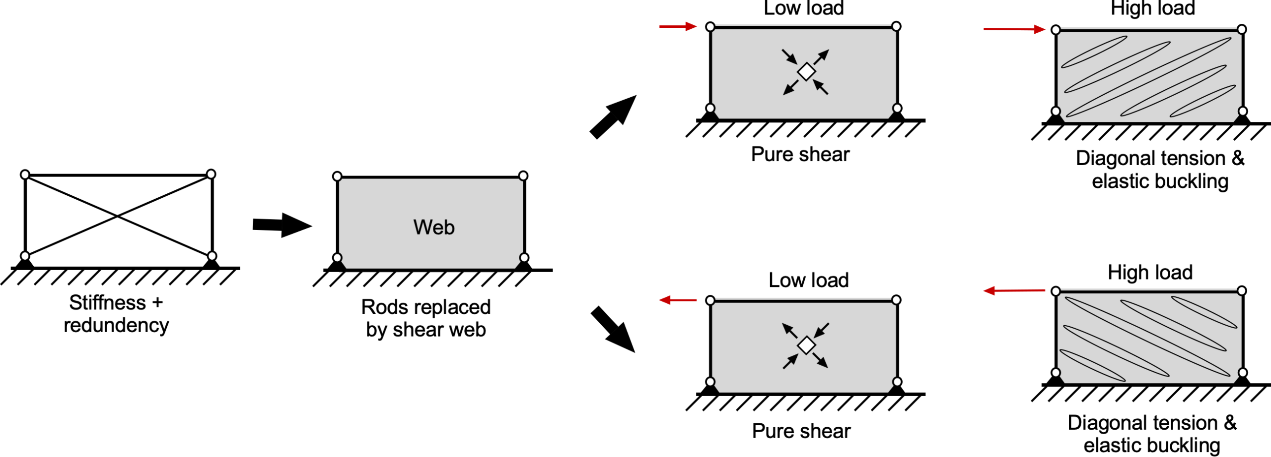
This transition introduced a new design challenge, namely the wrinkling or buckling of thin webs. Sheets subjected to compressive stress are prone to elastic instability, commonly referred to as buckling. Although buckling does not always lead to structural failure, it reduces effective stiffness and diminishes the ultimate load-carrying capacity of the structure, often requiring reinforcement or redesign. While increasing the web thickness is one solution, a more weight-efficient approach is to incorporate supporting members, called stiffeners or stringers, attached to the thin web to prevent local buckling.
As aircraft performance demands increased, particularly in terms of speed, maneuverability, and payload capacity, designers adopted fully stressed-skin and semi-monocoque structures. In these configurations, the external skin was no longer a passive aerodynamic fairing but became an active, load-bearing element of the airframe. The skin carried a substantial portion of the shear and bending loads, particularly under torsion, resulting in strong, lightweight, and inherently redundant structures.
Wing Structures
The wings generate lift to overcome the aircraft’s weight and are typically the most significant and heaviest structural components of the airframe. As such, they must be designed to be both extremely strong and as lightweight as possible. Wing geometry varies widely, and any particular design reflects a balance among structural strength, weight, and aerodynamic efficiency. In some aircraft, especially smaller or slower ones, wings may be externally braced using struts or wires that help support aerodynamic loads. While this approach allows for a lighter internal wing structure, it increases drag from the exposed bracing elements.
In the 1930s, the transition toward widespread use of monoplanes, which offered inherently lower aerodynamic drag than biplanes, created a growing demand for stronger, lighter wing structures. The increased flight speeds and wing loadings necessitated more advanced structural solutions beyond the trussed spars and externally braced wings commonly found in earlier designs. To address these demands, engineers introduced thin shear webs between the upper and lower flanges of the main spar, allowing the spar to function as an I-beam. This design efficiently distributed bending loads through the flanges, while the shear web carried transverse shear forces. In some aircraft, particularly those requiring higher torsional stiffness or longer spans, the I-beam configuration was replaced by, or supplemented with, a closed-section box beam, further improving shear and torsional resistance. These innovations marked a fundamental shift toward semi-monocoque construction, paving the way for stressed-skin designs that enabled cleaner aerodynamic profiles, reduced structural weight, and higher overall performance.
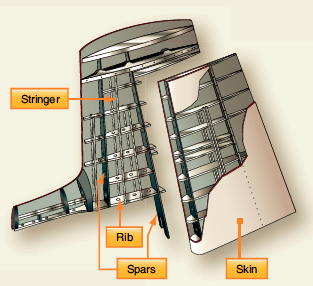
Today, wings are designed as complete cantilever beams to reduce drag, i.e., without any external bracing. Most wings have various internal structural members covered by a thin aluminum sheet skin; i.e., they are of a typical semi-monocoque stressed-skin design, as shown in the figure below. The internal structures of wings are made up of a lattice of spars and stringers that run spanwise and ribs or other types of formers that are placed chordwise. The main spar is the primary structural member of a wing, carrying most of the applied bending and shear loads. The skin carries most torsional loads and transfers the stresses to the wing ribs.
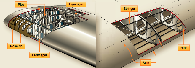
The ribs give the wing its aerodynamic (airfoil) shape and transmit the skin loads and stringers to the spars. The lightweight ribs are stamped from a flat aluminum sheet, and flanged holes are cut to reduce the assembly’s overall weight. Flanging the holes increases the resistance to buckling. The rib has a cap along its periphery, often in the form of a “T” or “L” shape, which stiffens and strengthens it before it is riveted to the wing skin. Ribs can extend from the wing’s leading edge to the rear spar or the wing’s trailing edge. Similar ribs are also used to construct the ailerons, elevators, rudders, and other components.
Spars & Bending Moments
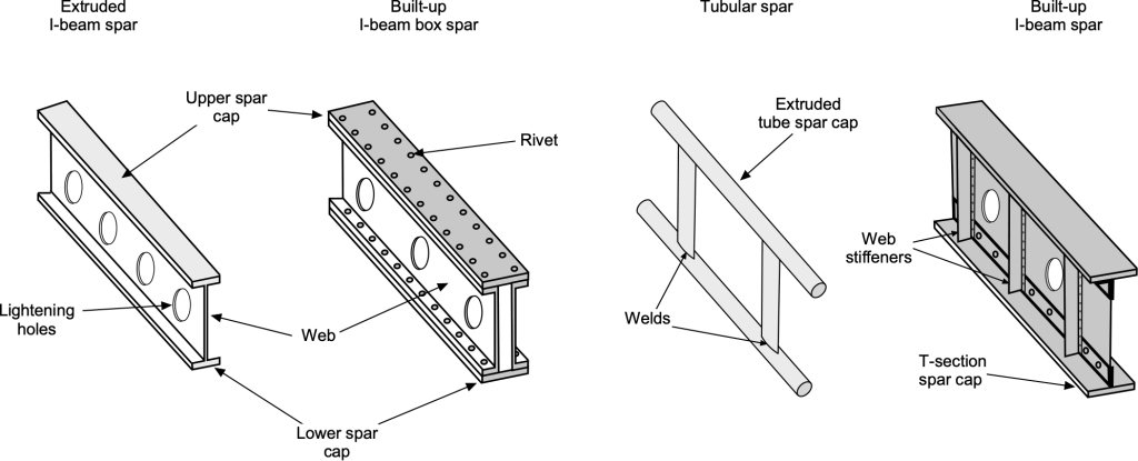
Depending on a specific aircraft’s design criteria, spars may be made of metal, wood, or composite materials. Bolts typically attach the spars to the fuselage, using various fittings to distribute the loads. Wing main spars are variations of I-beam structures made of solid extruded aluminum or several aluminum extrusions riveted together, as shown in the figure below. The I-beam’s top and bottom parts are called the spar caps, which take the compression and tensile loads produced from bending. The vertical section, commonly called the web, carries vertical shear loads. The web forms the spar’s principal depth portion, to which the caps are attached.
The stress, , in a wing spar can be calculated using the bending stress equation as given by
(4) 
where  is the bending moment,
  is the second moment of area of the cross-section, and
  is the distance from the neutral axis to the point where the stress is being calculated, as shown in the figure below. The highest stresses will occur in the spar caps, with the lower cap in tension and the upper cap in compression. For a symmetric cross-section, the neutral axis will be located halfway between the top and bottom of the section.
The second moment of area for the cross-section of the spar (or the wing as a whole) depends on the geometry of the cross-section. Values for common shapes are available, including rectangles, L-shapes, T-sections, U-sections, and I-beams. For example, a rectangular section of width  and height
  has a second moment of area of
(5) 
as shown in the figure below. For a standard symmetric I-beam with flange width  , flange thickness
  , web thickness
  , and total depth , then
(6) 
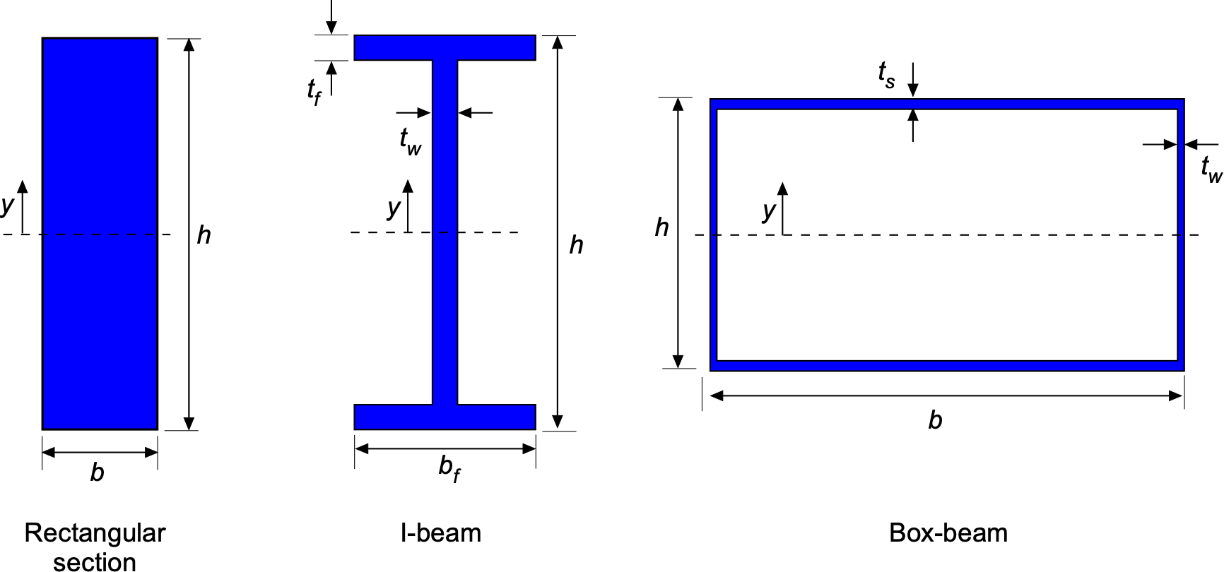
For thin-walled wing structures, a closed rectangular wing box of width , height , skin thickness  , and spar thickness has the approximate second moment of area
(7) 
For cases where the walls are very thin relative to the box dimensions, this result reduces to the thin-walled form given by
(8) 
In a typical light-aircraft wing, the primary load-carrying members are the spars and the skins; the ribs define the cross-sectional shape. The figure below shows a structural cross-section through a relatively simple wing, highlighting the locations of the main spar and a secondary rear spar. The main spar is placed close to the quarter-chord, where the aerodynamic lift is concentrated, and is sized to resist most of the wing’s bending moment. It usually has upper and lower caps (or flanges) connected by a vertical web, forming an I-beam or box-beam; the caps carry the dominant bending stresses in tension and compression, while the web transmits the associated shear. The caps may have different thicknesses, depending on the application.
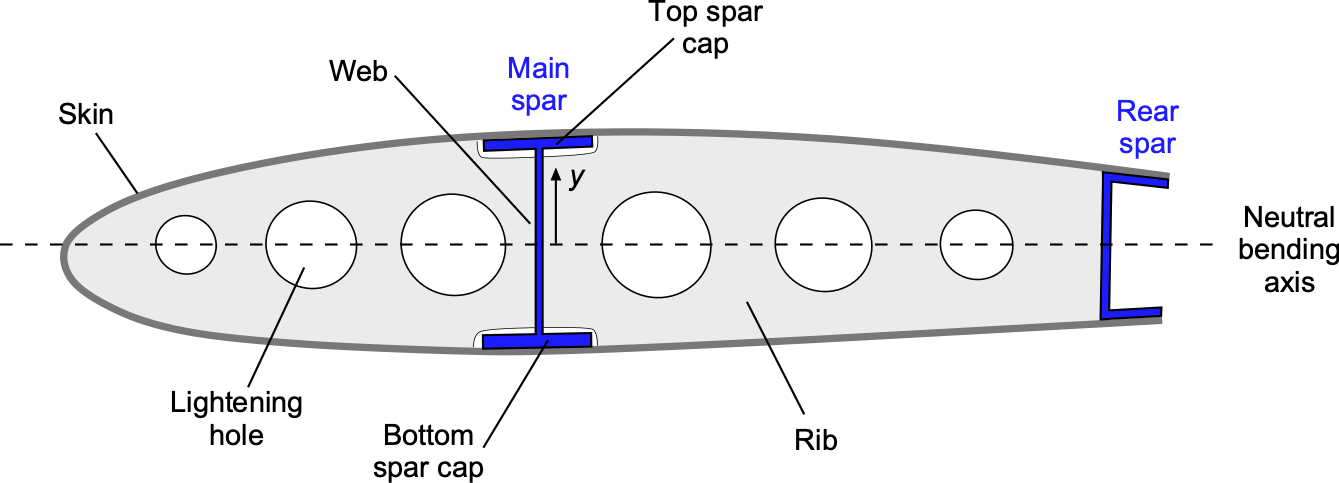
Further aft, typically around 55–65% of the chord, a lighter rear spar, often a C-section, is installed primarily to carry shear and to support the trailing-edge structure, including flaps and ailerons. Together with the ribs and skins, the main spar and rear spar form a closed torque box, so that torsional loads from aerodynamic pitching moments and control surface deflections are carried efficiently by shear in the skins and spar webs. The region between the spars, or between the front spar and the leading edge, is commonly used as a fuel bay or as a location for systems and control linkages, but it is still part of the structural wing box that provides both bending and torsional stiffness.
The upper and lower wing skins are bonded or fastened to the spar caps and ribs so that they participate fully in carrying bending loads, turning the entire cross-section into a built-up box beam. Under positive lift, the upper skin and upper spar caps carry compression, while the lower skin and lower caps carry tension. Local stiffeners and ribs distribute these loads into the skins, maintain the airfoil shape, and prevent local buckling of the thin sheet elements.
Multi-Spar Box Beams
Larger aircraft have multiple spars that can be built into a box beam, as shown in the figure below, which is a standard structural design for commercial airliners. It uses two or three main longitudinal spars to connect ribs and bulkheads, forming a box shape with tremendous bending and torsional strength. The interior of the wings may also be used for fuel tanks. The wing joints are sealed with a special fuel-resistant sealant, allowing fuel to be stored directly inside the structure, a design known as a wet wing. Alternatively, a separate fuel bladder or tank can be fitted inside the wing, a more typical implementation on smaller aircraft.
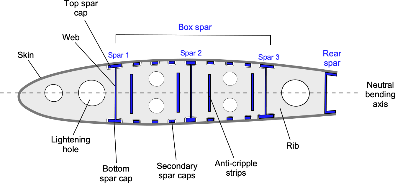
Secondary spars and stringers may be used to enhance strength, prevent buckling, and provide structural redundancy, helping make the wing fail-safe. In this context, fail-safe means that if a critical wing component fails, there is sufficient remaining structural redundancy and alternative load paths to prevent catastrophic failure. The FAA’s accepted definition of fail-safe is: “The attribute of the structure that permits it to retain its required residual strength for a period of unrepaired use after the failure or partial failure of a principal structural element.”
Today, composite materials are also used to manufacture fail-safe wing spars because of their excellent strength-to-weight ratio and resistance to fatigue cracking. Fatigue is the weakening of a material caused by repeated cyclic loading, which can result in a catastrophic failure of a wing spar or other structural component if a fatigue crack grows too much. Sharp corners are a common source of fatigue cracks, so rounded holes and smooth geometric transitions are used to enhance fatigue resistance.
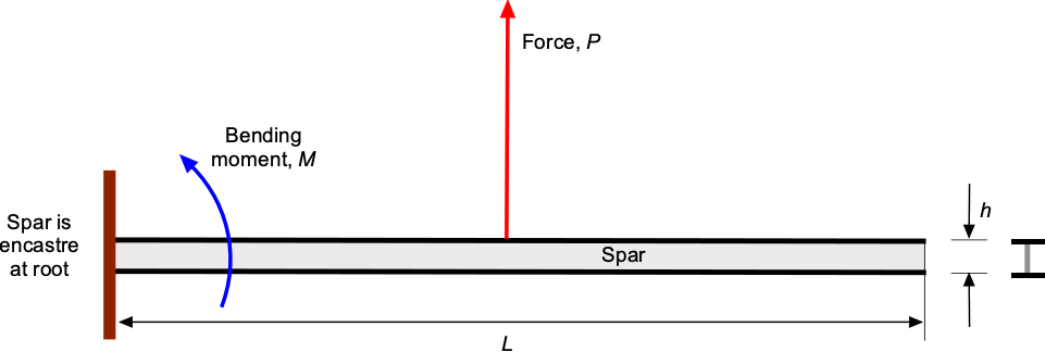
Check Your Understanding #2 – Bending moments and stress in a spar
An engineer needs to calculate the maximum stress in the lower cap of a cantilevered wing spar. The material is an aluminum alloy with a maximum allowable stress of 276 MPa. The spar is 3 m long and 0.1 m high. The spar must carry an in-flight load of 20 kN with a factor of safety of 5, which can be considered to act at the mid-length of the spar. The second moment of area of the spar is  m
m . The spar can be considered as encastré at the root, i.e., rigidly fixed.
Show solution/hide solution.
The bending moment, , on a cantilevered beam of length with a point load,  , acting at its mid-span is
![\[ M = n P \left( \frac{L}{2} \right) \]](https://eaglepubs.erau.edu/app/uploads/quicklatex/quicklatex.com-6faddb20eab6812ca85e17aab7098dfb_l3.svg "Rendered by QuickLaTeX.com")
where  is the factor of safety. The maximum bending stress in the beam will be in the spar caps at a distance
  from the neutral axis, so that at the root of the spar in the lower cap, the tensile stress will be
![\[ \sigma_{\rm max} = \frac{M}{I} \left( \frac{h}{2} \right) = \frac{n \, P \, L}{2 \, L \, I} \left( \frac{h}{2} \right) = \frac{n \, P \, L \, h}{4 \, I} \]](https://eaglepubs.erau.edu/app/uploads/quicklatex/quicklatex.com-bbea413647ce6d486753670085d3793c_l3.svg "Rendered by QuickLaTeX.com")
Substituting the numerical values gives
![\[ \sigma_{\rm max} = \frac{5.0 \times 20,000 \times 0.3}{4.0 \times 4.167 \times 10^{-5}} = 180~\mbox{MPa} \]](https://eaglepubs.erau.edu/app/uploads/quicklatex/quicklatex.com-7ece9dbee253551d3b4cddf95af7ec5c_l3.svg "Rendered by QuickLaTeX.com")
This stress value is well below the strength of the aluminum alloy (276 MPa), so the spar will easily carry the required load, including a significant margin.
Torsion & Shear Flow
When a wing is loaded in flight, it bends and it also twists under the action of aerodynamic pitching moments and trailing-edge control loads. As previously discussed, this twisting moment is known as torsion. The wing naturally twists about its elastic axis because that axis defines the direction along the span where bending and torsion are uncoupled. In a thin-walled wing box, torsion is resisted by shear stresses in the skins and spar webs. These shear stresses form a continuous distribution, called shear flow, denoted by  , as shown in the figure below. For a thin sheet of thickness , the shear flow is defined as
(9) 
where  is the shear stress. Notice that shear flow has units of force per unit length.
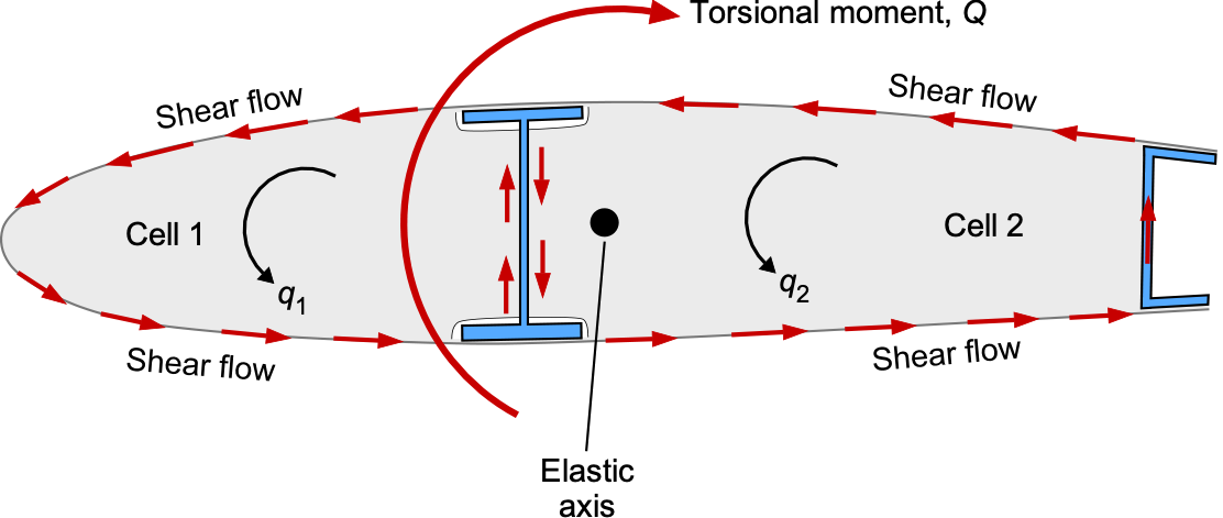
The torsion in a closed wing box is carried by a circulating shear flow around each closed cell, showing how the skins and spars share the torsional loads. The spars carry much of the vertical shear from bending, while the skins and webs together carry the shear associated with torsion. It will be appreciated that a multi-cell wing box provides greater torsional stiffness than a single-cell configuration. It creates two closed regions that can efficiently carry torsion. The circulating shear flows in these cells react with the aerodynamic pitching moments, control-surface hinge moments, and inertial torques that occur in flight.
This example of a two-cell wing box has two shear flows, one in each cell. Consider one of these thin-walled cells with a shear flow  acting tangentially around its perimeter. An element of wall of length
  produces an elemental twisting moment
  , where
  is the perpendicular distance from the centroid of the cell to the wall segment. Integrating around the entire closed co tour gives the total torque carried by that cell as
(10) 
For any thin-walled closed contour, the line integral  is a geometric quantity equal to twice the area enclosed by the cell, i.e.,
  . Substituting this result gives
(11) 
If the enclosed areas are  and
and  , with corresponding shear flows
  and
and  , with an applied torque
  , then torsional equilibrium requires that
(12) 
A second equation comes from compatibility. The twist per unit length must be the same in both cells. For a thin-walled closed section, the twist rate in cell  is
is
(13) 
Applying this to the two cells gives
(14) 
where  is the shear modulus and the line integrals run once around each cell. Because the entire wing box must twist as a single component, the compatibility condition requires
  , This condition can be used to solve for and . Once the shear flows are known, the shear stresses follow from
  .
.
The concept of the shear center follows directly from these ideas. The shear center is the point on the cross-section where a transverse load must act so that the section bends without twisting. If the load is applied at any other point, the shear flows in the section’s walls produce a torsional moment in addition to bending. For a symmetric two-cell rectangular box of uniform thickness, the shear center lies at the geometric center of the box because the shear flows in the upper, lower, and side walls are balanced and produce no net twisting moment.
Braced Wing Structures
A strut-braced wing is a typical structural configuration in light aircraft, where an external diagonal strut connects the wing panel to a lower joint on the fuselage, as shown in the figure below. The purpose of the strut is to relieve bending loads in the wing root by transmitting a portion of the aerodynamic lift through axial forces rather than internal bending alone. Although aerodynamically less clean than a cantilever wing and has higher drag, the strut-braced arrangement offers significant structural efficiency, permitting lighter spars and reduced wing weight for the same load-carrying capacity. The Cessna 172 series exemplifies the effectiveness and durability of the strut-braced wing configuration, which has remained essentially unchanged throughout decades of production.
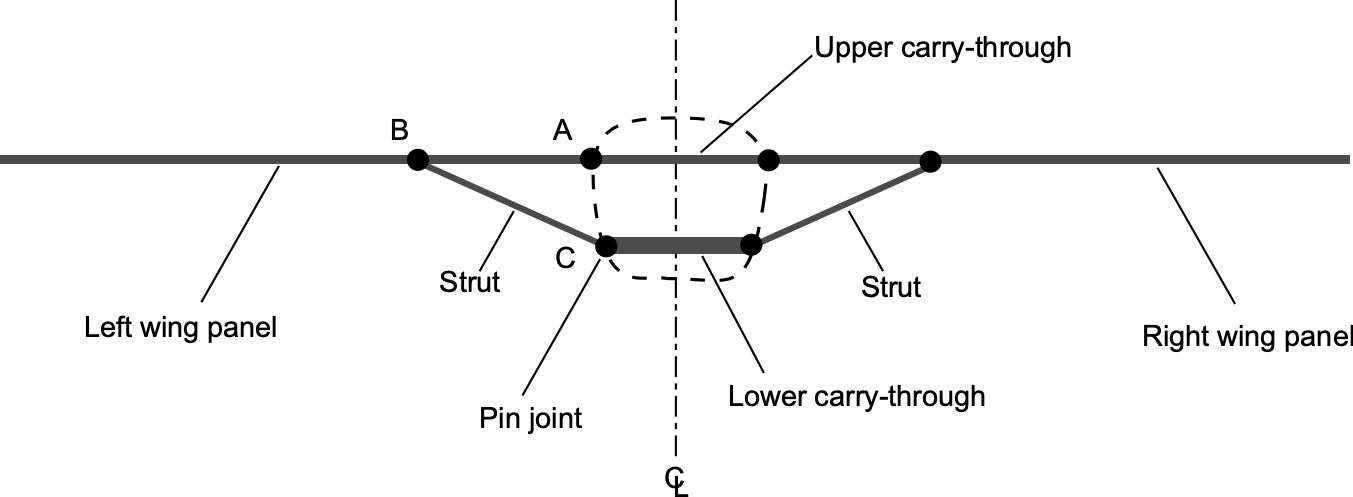
To study the internal forces in such a structure, the wing and its bracing elements can be idealized as a pin-jointed framework composed of the wing panels, the upper and lower carry-through members in the fuselage, and the left and right diagonal struts. Under steady-level flight, the wing panels carry a distributed aerodynamic lift, and the combined structure transfers this load to the fuselage through a system of axial forces in the struts and carry-throughs, as well as shear and bending in the wing beams.
Consider the left half of a strut-braced wing, idealized as shown in the figure below. The wing panel extends from the root pin at  to the free tip at
  , and the strut attaches to the wing at point
  located at
  . The distributed aerodynamic lift acting on one wing panel is
(15) 
so the total upward load on the left wing is  . The root at is a pin support, and the strut attaches through a pin joint at . Because all joints are frictionless pins, the only vertical forces acting directly on the wing panel are the root reaction
  , the distributed lift
  , and the downward vertical component
  of the strut force. The lower carry-through and fuselage joint at
  reacts the remaining components of the strut load but does not apply distributed loads to the wing panel.
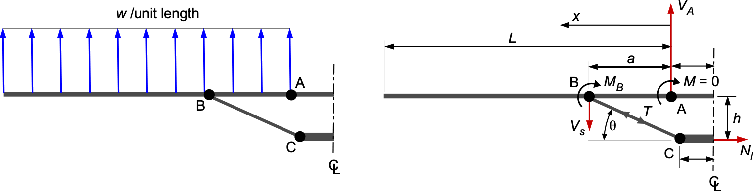
Summing vertical forces on the wing panel gives
(16) 
Taking moments about the root pin at eliminates and gives
(17) 
from which
(18) 
and, therefore, the root reaction is
(19) 
To determine the internal shear in the wing panel, take upward shear as positive. For the inboard region  (between the root and the strut attachment), then
(20) 
For the outboard region  , the left segment of the beam also contains the downward strut force, i.e.,
(21) 
This expression satisfies  at the free tip, as expected, and shows that the maximum internal shear occurs at the root pin, i.e.,
(22) 
The bending moment satisfies  , with
  at the pin support. For the inboard region
(23) 
For the outboard region , using  at the free tip, then
(24) 
and
(25) 
which is the resultant bending moment from the outer wing panel. The maximum bending moment occurs at the point where the shear passes through zero. Solving  for
for  gives the station of zero shear in the inboard portion of the wing, i.e.,
(26) 
For typical strut geometries, this point lies between the root and the strut attachment, so the maximum bending moment occurs in this inboard bay of the wing panel, which needs to be particularly strong and stiff to carry the loads.
The support strut itself is a two-force member[2] carrying only axial load. Its vertical component on the wing is , so the axial tension in the strut is
(27) 
where the strut angle is
(28) 
Each strut has a horizontal component  , and the two symmetric struts together transmit this horizontal load into the lower carry-through. The resulting axial force in the lower carry-through is, therefore,
(29) 
The lower carry-through structure must also be strong enough to withstand landing gear loads, which are transmitted through this part of the structure.
Check Your Understanding #3 – Stress & Strain in a Wing Strut
Consider the left wing strut of a light aircraft in steady  level flight. The axial force in the strut from the preceding analysis is
![\[ T = \frac{W L}{4 a \sin\theta} \]](https://eaglepubs.erau.edu/app/uploads/quicklatex/quicklatex.com-61f50a98a9a1e3c0b91653383ef96bd1_l3.svg "Rendered by QuickLaTeX.com")
Use the following representative values: Airplane weight  = 10,000 N, half-span = 5.5 m, strut attach point
  = 3.0 m, vertical drop = 1.2 m. Assume a circular strut with diameter
  = 35 mm and wall thickness = 2 mm, made of aluminium with Young’s modulus
  = 70 GPa. Determine: (1) the axial force
  in the strut; (2) the axial stress
  ; (3) the axial strain
  .
.
Show solution/hide solution.
The strut angle is
![\[ \theta = \tan^{-1}\!\left(\frac{h}{a}\right) = \tan^{-1}\!\left(\frac{1.2}{3.0}\right) = 21.8^\circ \]](https://eaglepubs.erau.edu/app/uploads/quicklatex/quicklatex.com-ccad71cc6a1813b26e265ee10ef409f2_l3.svg "Rendered by QuickLaTeX.com")
The axial force in the strut is
![\[ T = \frac{W L}{4 a \sin\theta} = \frac{10{,}000 \times 5.5}{4 \times 3.0 \times \sin 21.8^\circ} = 1.23 \times 10^4~\text{N} \]](https://eaglepubs.erau.edu/app/uploads/quicklatex/quicklatex.com-b5199cb9d5e6ce41e604c019be0cee78_l3.svg "Rendered by QuickLaTeX.com")
The cross-sectional area of a thin-walled circular tube is approximated by
![\[ A_s \approx \pi d_s t_s \]](https://eaglepubs.erau.edu/app/uploads/quicklatex/quicklatex.com-7e1dcb233146b64cf29e75e975b684b0_l3.svg "Rendered by QuickLaTeX.com")
so
![\[ A_s = \pi (0.035)(0.002) = 2.20 \times 10^{-4}~\text{m}^2 \]](https://eaglepubs.erau.edu/app/uploads/quicklatex/quicklatex.com-7b6965dd318533328a4632eebfb0e5c1_l3.svg "Rendered by QuickLaTeX.com")
The axial stress in the strut is
![\[ \sigma_s = \frac{T}{A_s} = \frac{1.23\times10^4}{2.20\times10^{-4}} = 5.6\times10^7~\text{Pa} = 56~\text{MPa} \]](https://eaglepubs.erau.edu/app/uploads/quicklatex/quicklatex.com-31da80ff74e33fc923c29dd0fea39bee_l3.svg "Rendered by QuickLaTeX.com")
and the axial strain is
![\[ \varepsilon_s = \frac{\sigma_s}{E_s} = \frac{5.6\times10^7}{7.0\times10^{10}} = 8.0\times10^{-4} \]](https://eaglepubs.erau.edu/app/uploads/quicklatex/quicklatex.com-9900cb509eef1ad354a698b0474b7c08_l3.svg "Rendered by QuickLaTeX.com")
Because strain is dimensionless, this corresponds to an extension of 0.8 mm per meter of strut length.
Fuselage Structures
The fuselage is the primary structure, or “body,” of the aircraft. It provides space for the aircrew, passengers, cargo, and other equipment. There are two basic types of fuselage construction: the truss type and the monocoque/semi-monocoque type. In single-engine aircraft, the fuselage also usually houses the engine. In multi-engine aircraft, the engines may be located in the fuselage, attached to it, suspended from or contained within the wings.
A truss-type fuselage is a lightweight framework of steel-alloy tubes that provides stiffness and resists deformation under applied loads. As shown in the figure below, this type of structure is sometimes called a space-frame design. Diagonal web members provide most of the truss’s bending and torsional stiffness. The truss-type fuselage frame is typically constructed from lightweight steel-alloy tubing, which is welded together, allowing all truss members to carry primarily tension and compression loads.
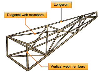
In some aircraft, truss fuselage frames may consist of aluminum alloy rods riveted or bolted at their ends using gusset plates. The truss-type fuselage is typically covered with fabric, although thin plywood or aluminum sheets may be added to provide additional stiffness and improve durability. Although it is often used on smaller general aviation aircraft, the design does not scale well for larger aircraft because it becomes too heavy compared to other designs.
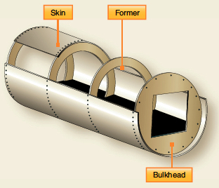
The most common type of fuselage construction for aircraft is the monocoque or semi-monocoque design. As shown in the figure below, the monocoque (i.e., single-shell) fuselage relies primarily on the skin’s strength to carry the loads. In this case, the skin must be thick enough to prevent large compressive deformations or buckling, which increases the structure’s weight. Because the skin is designed to carry significant loads, it is considered a stressed-skin design. Skin buckling is likely to occur under bending, compression, or torsion loads in a monocoque structure.
Most modern aircraft utilize semi-monocoque construction, as illustrated in the figure below. This construction combines a lightweight skin with internal reinforcements, such as frames, longerons, and stringers, to create a strong and rigid structure. The skin, made thinner and lighter, is supported by these components, which help distribute loads and prevent buckling. Longerons, typically aluminum alloy extrusions in “U” or “T” sections, run across multiple frames, providing significant stiffness and supporting primary bending, torsion, and compressive loads. These elements are joined using rivets and other fasteners, ensuring durability while optimizing the strength-to-weight ratio. This design makes it ideal for modern aircraft, offering superior resistance to aerodynamic and structural stresses.
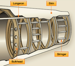
In a semi-monocoque structure, shorter but more numerous stringers are also used to increase rigidity by supporting the skin and preventing skin buckling. Attached beneath the skin, they help maintain its shape and may be riveted directly without always connecting to frames or ribs. Both stringers and longerons primarily work in tension and compression, distributing loads efficiently across the fuselage to ensure its structural integrity.
For many purposes, the fuselage can be idealized as a beam that carries loads from bending, shear, and torsion. Under a bending moment  , the normal stress in a thin-walled fuselage section is
(30) 
where  is the distance from the neutral axis and is the second moment of area. In a truss-type fuselage, this bending is resisted by axial forces in the individual tubes, whereas in a semi-monocoque structure, the bending load is shared between the longerons, stringers, and skin.
Each truss member, or longeron, behaves as a two-force member and carries only an axial load  . Its average stress is
(31) 
where is the cross-sectional area of the member. In a truss fuselage, the pattern of tension and compression among the members provides the airframe’s overall bending and torsional stiffness.
In a monocoque or semi-monocoque fuselage, the thin skin is also part of the load-carrying system. The skin primarily carries shear, while the longerons and stringers carry the majority of the normal (bending) stresses. For torsion, a thin-walled closed fuselage acts like a tube, with an average shear stress of the form
(32) 
where is the applied torque,  is the skin thickness, and
  is the enclosed area. This thin-walled “tube behavior’’ explains the high torsional stiffness and strength of semi-monocoque construction even when the skin is relatively thin and light.
How to drive a rivet!
A solid rivet is the most common type of fastener used in aircraft structures. The principle of driving a rivet is relatively simple.
- Drill several matching holes in the two pieces to be joined.
- Hold the components together with clamps or clecos.
- Slide in one solid rivet until the head of the rivet is firmly against the outer part of the structure.
- Hold the rivet head in place, then drive or buck the rivet tail from the other side with a bucking bar until the rivet is squeezed (deformed) to hold the pieces together tightly.
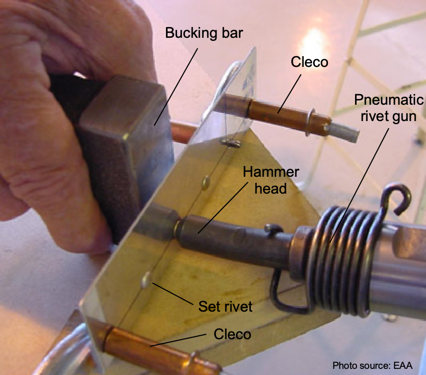 Rivets are strong because they fill the entire hole with a solid aluminum plug. They are also very light and inexpensive. However, setting rivets requires skill, and sometimes more than one person is needed to install them. The use of a pneumatic hammer (with a set shaped to the rivet head) and a bucking bar (used for the tail of the rivet) speeds up the installation process, which can involve hundreds or thousands of rivets, even on a modest-sized piece of structure. Riveting can be labor-intensive, but the process results in a strong, lightweight, and durable structure.
Most, if not all, commercial aircraft have pressurized fuselages, meaning the cabin pressure is increased to create a differential pressure between the cabin and the outside atmosphere. Pressurization is achieved by designing an airtight fuselage that is pressurized with a compressed-air source, typically engine bleed air. In most pressurized airplanes, the cabin pressure is maintained at an altitude equivalent to approximately 6,000 ft to 8,000 ft (about 2,000 m to 2,500 m) to ensure good passenger comfort. Nevertheless, some passengers may still exhibit mild hypoxia symptoms (oxygen deprivation) during long-haul flights, contributing to the all-too-frequent malady known as jet lag.
Structurally, pressurization causes significant tensile and hoop stresses to develop in the fuselage, as shown in the figure below, thereby increasing the complexity of its design and its structural weight. The fuselage is an enormous pressure vessel that expands like a balloon as the aircraft climbs to altitude. The ceiling for most commercial transport airplanes is often limited by cabin pressurization requirements, which set a structural stress limit on the fuselage. Naturally, stresses can be reduced by increasing the thickness of the fuselage skin; however, this approach also significantly increases the airframe’s weight.
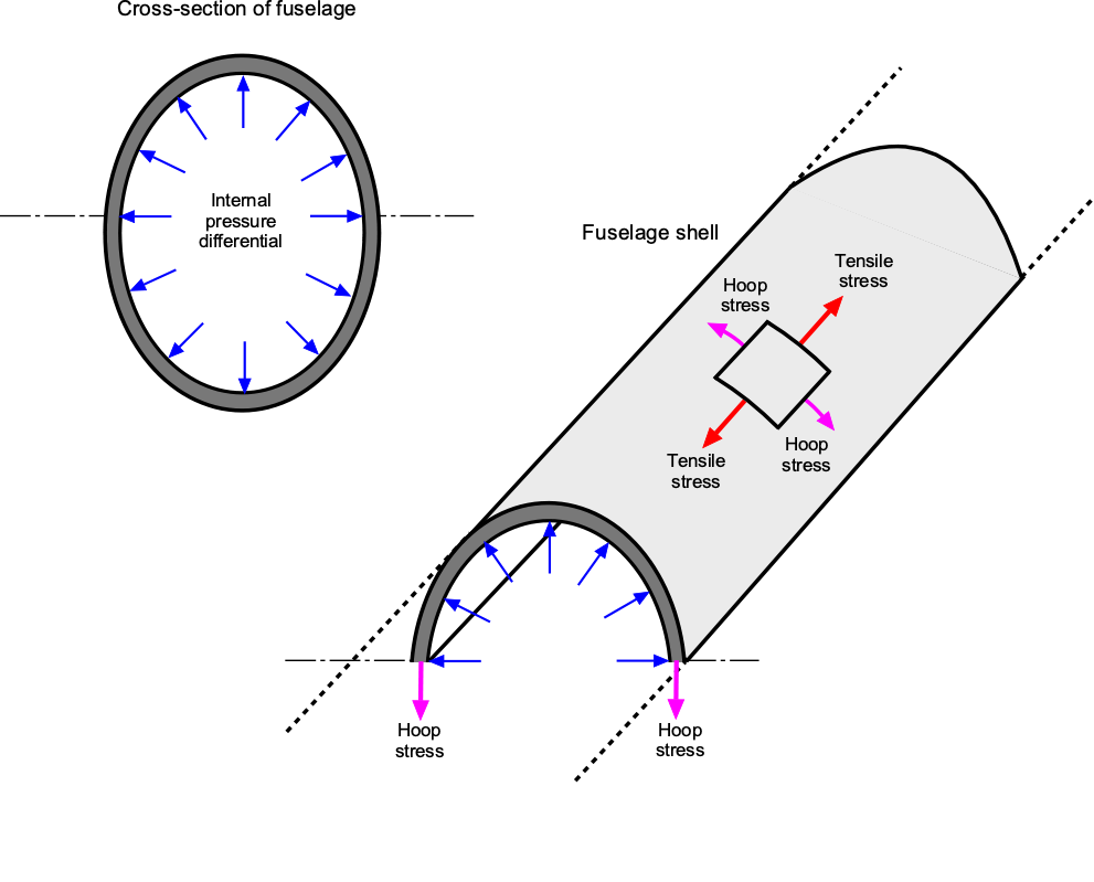
The hoop stress  in a cylindrical pressure vessel is generally the dominant tensile stress and is given by
(33) 
where  is the differential pressure across the skin,
  is the mean radius of the fuselage, and is the wall (skin) thickness. The longitudinal or axial stress
  is approximately half the hoop stress and is given by
(34) 
These stress limits impose critical constraints on fuselage design. The maximum allowable cabin differential pressure, and hence the maximum cruise altitude, is bounded by the material strength and thickness of the fuselage skin. Although increasing skin thickness reduces stress levels, it also adds structural weight, diminishing payload capacity and fuel efficiency. Therefore, optimizing fuselage design involves balancing structural strength, weight efficiency, and operational ceiling.
Another type of semi-monocoque structure is the geodesic design, pioneered by the British aeronautical engineer Barnes Wallis in the 1930s. The famous Vickers Wellington bomber, depicted in the photograph below, was constructed with a geodesic structure and demonstrated its structural integrity even after sustaining significant combat damage. In a geodesic construction, the longitudinal and diagonal members follow helical paths around the fuselage or wing, intersecting to form a network of diamond-shaped cells. Loads applied at any point on the structure are carried through this network and split among many paths, which greatly reduces the stress in any individual member. This load sharing produces a structure with excellent strength to weight characteristics and inherent redundancy. A local failure does not cause a catastrophic collapse because the surrounding members continue to carry load.
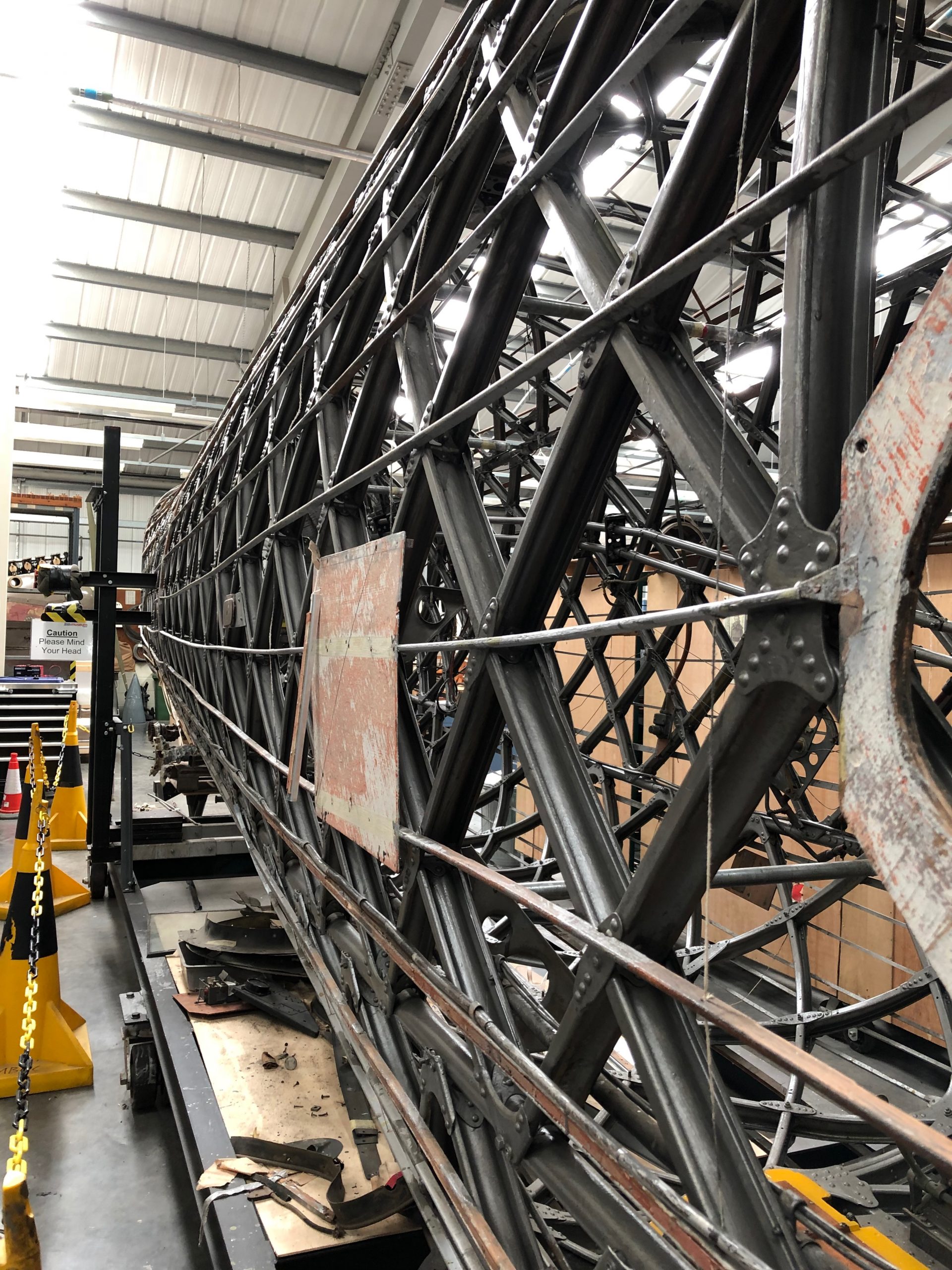
The efficiency of the geodesic design relies on the use of a fabric or thin non-structural covering. The skin does not carry primary loads; instead it transmits aerodynamic loads into the underlying lattice. When fabric is used, the overall structure remains very light. However, if the aircraft requires a pressurized fuselage, the skin must become a load-carrying member. Replacing the fabric with stressed metal skin adds substantial weight and removes many of the weight savings that make the geodesic system attractive.
Although variants of this design have been used in spacecraft structures and other specialized applications, the geodesic approach is generally less practical for modern aircraft. Manufacturing and repairing the lattice is labor intensive, and the weight penalties associated with metal skins make the more conventional semi-monocoque design preferable for pressurized or high-performance airframes. Nonetheless, the geodesic construction remains an important milestone in structural design and is an excellent illustrative example of how geometry and load-path redundancy can be used to create efficient lightweight structures.
Empennage Structures
The tail assembly of an aircraft is called the empennage. The structure of the vertical (fin) and horizontal stabilizers is very similar to that used in wing construction, including spars, ribs, and stringers, all of which are covered with a thin skin. They perform the same functions: shaping and supporting the structures and transferring stresses to the fuselage. However, the stabilators also have control surfaces, which means that additional structural requirements exist from the airloads produced by control deflections. For example, a rudder application alters the force on the fin, resulting in torsion. These loads are, in turn, applied to the fuselage as both bending and torsional moments.
Flight Control Structures
An airplane’s primary flight control surfaces are the ailerons, elevators, and rudder. Other movable surfaces include flaps and spoilers. The ailerons are attached to the trailing edge of both wings and are used for roll control. The elevator, located on the trailing edge of the horizontal stabilizer, controls the aircraft’s pitch. The rudder, hinged to the trailing edge of the vertical stabilizer, provides yaw (directional) control.
Control surfaces are typically made from an aluminum alloy structure built around a single spar member or torque tube to which ribs are fitted and skin is attached. Primary control surfaces and flaps can also be constructed from composite honeycomb materials, a method used primarily on larger commercial airliners where excessive weight growth is a concern. Other sandwich construction structures may include cabin floors, nose cones, and engine cowlings.
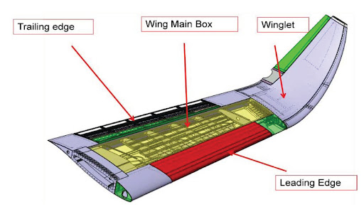
Winglets
A winglet is a vertical upturn of the wing tip, as shown in the figure below. Winglets are used to improve the aerodynamic efficiency of an airplane by modifying the airflow near the tip of the wing. As air moves around the wing, the high-pressure air from the lower surface tends to curl upward around the tip and mix with the lower-pressure air above. This curling motion produces a swirling flow pattern called a wing tip vortex, which wastes energy and contributes to an additional component of drag whenever the wing is producing lift. By adding a small, carefully shaped surface at the tip, the winglet helps control and reduce this swirling motion so that less energy is lost.
Winglets are made from aluminum or composite materials and are often retrofitted to existing wings to improve an airplane’s performance. Although they may appear to be small attachments, winglets carry significant aerodynamic loads. Therefore, a winglet must be structurally tied into the main wing box at the tip, where the structure is strong enough to resist the bending and twisting forces generated in flight. This reinforcement ensures that the winglet becomes a fully integrated part of the wing.
Stress Analyses
A structural stress analysis involves determining aerodynamic and other loads and evaluating the resulting stresses imposed on the structural components. While a stress analysis may be conducted on separate components or assemblies, any single structural member may be subjected to a combination of stresses from multiple loading paths. Therefore, a thorough stress analysis generally must consider the aircraft’s total structure to ensure it is strong and stiff enough to carry all flight and ground loads.
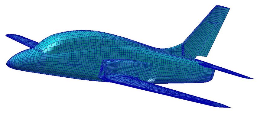
This type of stress analysis is performed using the finite-element method (FEM). The FEM is a numerical method in which the aircraft structure is modeled as a set of finite blocks, or lattice elements, interconnected at discrete points called nodes; an example of a lattice used for an entire aircraft is shown in the figure below. The process begins with creating a geometric model of the aircraft and its detailed components using Computer-Aided Design (CAD) software. Each block or finite element may have different properties, such as thickness and material characteristics, reflecting the characteristics of aerospace materials like composites and metal alloys, which gives the FEM tremendous optimization design capabilities. Regions between the fuselage, engine nacelles, and wings, as well as cutouts such as cockpit windows, require particular attention in FEM to avoid local stress concentrations.
Material properties, such as Young’s modulus, Poisson’s ratio, and density, are assigned to each element. Boundary conditions, including constraints, loads, and thermal effects, are applied to the model to represent the operating environment and mission requirements. The assembly of system equations involves formulating the stiffness matrix by aggregating contributions from individual finite elements and assembling the load vector to account for applied loads and environmental conditions. For linear systems, the displacement vector ![[ u ]](https://eaglepubs.erau.edu/app/uploads/quicklatex/quicklatex.com-6390e12d67bd11e712fb7d2746ccc6ca_l3.svg "Rendered by QuickLaTeX.com") is determined by solving the equation
is determined by solving the equation
(35) ![\begin{equation*} [ K ] \{ u \} = \{ F \} \end{equation*}](https://eaglepubs.erau.edu/app/uploads/quicklatex/quicklatex.com-09bdabd895ca988fa9e0ec844305d5d2_l3.svg "Rendered by QuickLaTeX.com")
where ![[ K ]](https://eaglepubs.erau.edu/app/uploads/quicklatex/quicklatex.com-46eb26690412aa8e89f55c2fd589e981_l3.svg "Rendered by QuickLaTeX.com") represents the stiffness matrix and
represents the stiffness matrix and  is the load vector comprising of forces and moments. This equation describes the relationship between the loads acting on all nodes in the mesh and the displacements and rotations at those nodes. The nodal displacements and rotations of the structure are the unknowns in the FEM.
Solution techniques in the FEM encompass a variety of numerical methods. One approach is to invert the stiffness matrix to find  and solve for
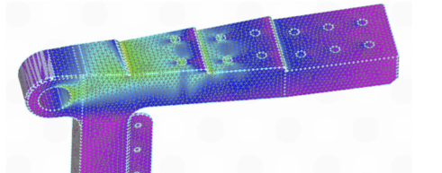
  . However, directly inverting a large matrix is not numerically efficient. Instead, preferred methods iteratively approximate the displacement vector to converge to a solution. Post-processing tools are then employed to visualize and interpret the results, as shown in the figure below for a spar lug, which is color-coded by stress level (blue indicating the lowest). Notice the higher stresses around the bolt holes. The idea is to distribute the stresses so that they “flow” smoothly into the primary attachment points without large concentrations.
From the FEM results, engineers can assess the structural integrity of the flight vehicle by analyzing stresses, strains, and overall deformations to ensure that the vehicle and its components meet safety, performance, and certification requirements. In this regard, designing an aircraft or spacecraft may involve finding the strongest and most durable structure with the minimum possible weight, while also ensuring good fatigue and corrosion resistance, as well as other desirable characteristics.
Simple Application of the FEM
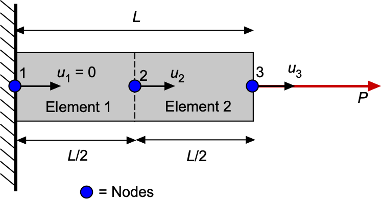
The complete FEM workflow can be illustrated with a single structural component. The FEM process encompasses element formulation, assembly, application of the boundary conditions, solution of ![[K]\{u\}=\{F\}](https://eaglepubs.erau.edu/app/uploads/quicklatex/quicklatex.com-908e629c7b01c801d50ba395bfbb8610_l3.svg "Rendered by QuickLaTeX.com") , and post-processing to obtain the stresses and strains. Consider a straight aluminum tie bar of length = 1.0 m and constant cross-sectional area = 400 mm
, and post-processing to obtain the stresses and strains. Consider a straight aluminum tie bar of length = 1.0 m and constant cross-sectional area = 400 mm . One end of the bar is fixed (encastré), and the other end is loaded in tension by a force = 20 kN. The material has Young’s modulus = 70 GPa. In the FEM analysis, the bar is discretized into two equal finite elements, each of length
  =
=  = 0.5 m, so that there are three nodes with axial displacements
  , as shown in the figure below.
For a 1-dimensional axial bar, the element stiffness matrix is
(36) ![\begin{equation*} [ k^{(e)} ] = \frac{EA}{L_e} \begin{bmatrix} 1 & -1 \\ -1 & 1 \end{bmatrix} \end{equation*}](https://eaglepubs.erau.edu/app/uploads/quicklatex/quicklatex.com-85e0448b06b704f66bffcc0559f975ff_l3.svg "Rendered by QuickLaTeX.com")
This expression follows directly from the axial behavior of a bar element. For a 1-dimensional element with nodal displacements  and
and  , the axial strain is
(37) 
and Hooke’s law gives the corresponding stress  . The internal axial force, , in the element is then
(38) 
A positive extension  pulls node 1 to the right and node 2 to the left, so the nodal forces are
(39) 
Substituting for and writing the result in matrix form gives
(40) ![\begin{equation*} \begin{Bmatrix} F_1 \\[8pt] F_2 \end{Bmatrix} = \frac{EA}{L_e} \begin{bmatrix} 1 & -1 \\ -1 & 1 \end{bmatrix} \begin{Bmatrix} u_1 \\ u_2 \end{Bmatrix} \end{equation*}](https://eaglepubs.erau.edu/app/uploads/quicklatex/quicklatex.com-f2e0927cacc7622747f6d5324e451369_l3.svg "Rendered by QuickLaTeX.com")
which is exactly the element stiffness relation ![\{F^{(e)}\}=[k^{(e)}]\{u^{(e)}\}](https://eaglepubs.erau.edu/app/uploads/quicklatex/quicklatex.com-01d1c3808306ad6a82627b03b658db19_l3.svg "Rendered by QuickLaTeX.com") .
.
In this example, substituting  Pa,
Pa,  m, and = 0.5 m gives
  N/m. The global stiffness matrix assembled from the two elements is then
(41) ![\begin{equation*} [ K ] = 56\times 10^9 \begin{bmatrix} 1 & -1 & 0 \\ -1 & 2 & -1 \\ 0 & -1 & 1 \end{bmatrix} \end{equation*}](https://eaglepubs.erau.edu/app/uploads/quicklatex/quicklatex.com-a55711cb3d3019baf350bee33357baba_l3.svg "Rendered by QuickLaTeX.com")
The applied load vector is
(42) 
because a load is only applied at node 3. The only given boundary condition is that node 1 is fixed, so  . Solving the reduced system gives
(43) ![\begin{equation*} \begin{bmatrix} 2 & -1 \\ -1 & 1 \end{bmatrix} \begin{Bmatrix} u_2 \\ u_3 \end{Bmatrix} = \begin{Bmatrix} 0 \\[8pt] \dfrac{20{,}000}{56\times 10^7} \end{Bmatrix} \end{equation*}](https://eaglepubs.erau.edu/app/uploads/quicklatex/quicklatex.com-e66e0e49cfccec8f3deaaab8cff1971d_l3.svg "Rendered by QuickLaTeX.com")
Therefore, the nodal displacements are
(44) 
The element strains are
(45) 
and the corresponding stresses are
(46) 
This simple example illustrates all the essential steps of the FEM using only two elements and three nodes. However, in a real structure, the same procedures extend directly to dozens, hundreds, or even millions of elements. Each additional element contributes its own small stiffness matrix to the global system, and each new node adds extra unknown displacements to the global displacement vector.
The whole assembly process repeats the pattern, with element equations stacked and merged into a large matrix according to shared nodes. Boundary conditions are then applied to the selected degrees of freedom, and the resulting global matrix equation is solved for all nodal displacements. In this way, the FEM scales naturally to more complex structures, such as spars, ribs, fuselage frames, landing gear fittings, and complete wing-fuselage assemblies.
Fail-Safe & Safe-Life Structural Designs
Aerospace engineers have developed safe-life and fail-safe design philosophies for structural design. Fail-safe designs incorporate techniques such as structural redundancy and multiple load paths to prevent catastrophic failure of a single component. Safe life design is the philosophy that a component or system is designed not to fail during operational use within a specific period. This period may be defined by the number of flight hours, takeoffs and landings, years of operation, or some combination. Testing and analysis can estimate the expected life of the component or system, applying a margin of safety as well. The part or component must be removed from operational service and scrapped at the end of its expected life.
The decision between a safe-life and a fail-safe structural design depends on a cost-benefit analysis of the likelihood and potential consequences of failures. The benefit of a safe-life design is the freedom from specific inspection processes and maintenance cycles, which can save an operator significant time and money. However, fail-safe designs are usually heavier and more expensive. Safe-life designs are often simpler and lighter, aiming to minimize unplanned maintenance and the possibility of failure by designing components to last for a specific period.
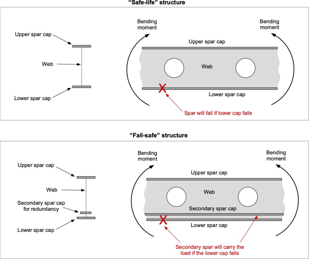
An example of a safe-life versus failsafe structure is illustrated in the figure below for a wing spar, a critical component of an aircraft. The upper spar cap will be in compression, and the lower cap will be in tension; the lower cap is more critical for fatigue failure. Notice that in the event of a failure of the lower spar cap, the fail-safe structure has sufficient redundancy because of an alternative load path that can carry the bending moment loads. Unless the fatigue cracking of a safe-life structure is identified before progressing too far, the spar will fail catastrophically under load.
The final decision to employ one or the other design philosophy must be made on a case-by-case basis, and the specific application of the parts or systems to different types of airframes must be determined. For example, commercial airliners and military airplanes are designed using fail-safe principles. The use of a fail-safe design philosophy in the aircraft industry provides structural redundancy against damage that may occur during an aircraft’s service life. By incorporating fail-safe design features, which add some extra weight to the airframe, the consequences of a single component failure can be minimized, ensuring the safety of the aircraft and its passengers.
A small general aviation (GA) airplane may be designed using safe-life principles to save weight and cost, recognizing that it will likely be flown much less frequently and accumulate a significantly lower number of loading cycles over its life. This approach assumes that the components will not be subjected to a critical number of cycles during their lifespan and so do not require the same level of durability and safety factors as commercial or military aircraft. Nevertheless, catastrophic structural failures occur on aging GA aircraft, increasing the burden on the owner/operator to conduct more frequent inspections.
Buckling
Aerospace structures have relatively thin structural members, including thin external skins. Buckling may occur when an aerospace structural component is subjected to high compressive stresses. Buckling is characterized by a sudden out-of-plane deflection of the structural member with increasing compressive loading, as illustrated in the figure below. Different types of buckling may occur depending on the kind of structure and the applied loads.
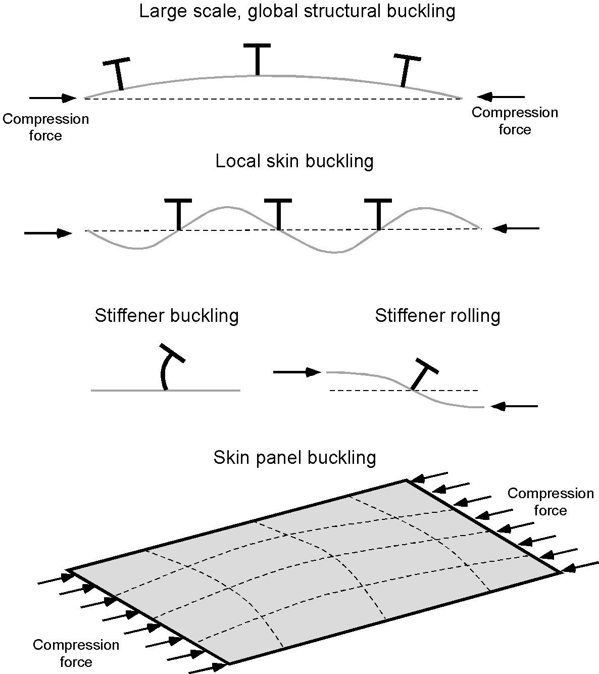
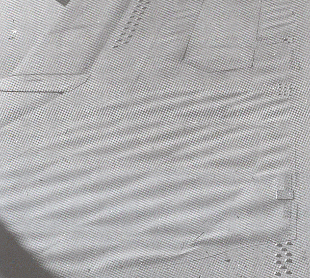
The thin skins on aerospace structures must be designed to prevent buckling under normally expected flight loads. This is done by supporting and stabilizing the skin from below using stringers or a substrate such as a honeycomb sublayer. However, stringers may also buckle when carrying high compressive loads, as shown in the image above. Under load, a certain amount of skin wrinkling in aerospace structures can generally be expected. Larger unsupported areas of the skin often tend to form mild waves or wrinkles, usually between frames and stiffeners, even under normal flight loads, as shown in the photograph below. Under these conditions, the skin undergoes mild elastic buckling and carries the normal compressive loads for which it was designed; it returns to its undistorted shape when the load is removed. Repeated elastic buckling at higher stress levels, however, does tend to increase the likelihood of fatigue cracking of thin skins.
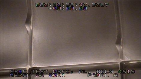
An aerospace structure may buckle, and its skins may wrinkle, even though the stresses are well below those needed to cause material failure. However, if sufficiently severe, buckling can result in permanent material deformations that significantly reduce the structure’s load-carrying capability. Further loading on a structure after severe buckling can lead to structural failure. The example shown in the image below is from a NASA test on a representative spacecraft structure, in which the stringers have undergone permanent (plastic) buckling, substantially reducing the component’s strength.
The onset of buckling can be predicted using theoretical methods first developed by Leonhard Euler. The Euler buckling formula allows a prediction of the maximum axial load an “ideal” structural member in the form of a column can carry before buckling. An ideal component is perfectly straight, made of a uniform homogeneous material, and free from any initial stress.
When the applied load reaches a critical load, the column reaches a state of unstable equilibrium. In this condition, even a small lateral load can cause the structure to buckle. The buckling force or critical force,  , can be written as
![\[ F_c = \frac {\pi^{2} \, E \, I}{(K \, L)^{2}} \]](https://eaglepubs.erau.edu/app/uploads/quicklatex/quicklatex.com-3b3a951397ad1eec15b1b7371ee3f663_l3.svg "Rendered by QuickLaTeX.com")
where is Young’s modulus of elasticity, is the second moment of area of the cross-section of the column, and is the unsupported length. The value of  , the effective length factor, depends on the end conditions of the column. For example, if both ends are pin-jointed (i.e., fixed but free to rotate), then
  . If both ends are rigidly fixed to prevent rotational movement (i.e., encastré), then
  , and the buckling force is twice as high. There are similar buckling formulae for plates and shells.
Check Your Understanding #4 – Estimating a buckling load on a structural member
A structural member in a wing structure is an unsupported aluminum alloy column measuring 2.1 m in length. The member can be considered fully encastré at both ends and has a second moment of area of 0.18 cm . Find the force required to produce compressive buckling. Young’s modulus for the aluminum alloy material is 69.0 GPa.
Show solution/hide solution.
The Euler buckling load can be calculated using
In this case, the member is encastré at both ends, so = 0.5. Inserting the known values and being careful to convert quantities to base SI units gives
![\[ F_c = \frac {\pi^{2} \, E \, I}{(K \, L)^{2}} = \frac{ \pi^2 \, 69.0 \times 10^9 \times 0.18 \times 10^{-4}} { (0.5 \times 2.1)^2} = 1,112~\mbox{kN} \]](https://eaglepubs.erau.edu/app/uploads/quicklatex/quicklatex.com-26f7917d387d020fb4535cfa9948af59_l3.svg "Rendered by QuickLaTeX.com")
Thermal Considerations
Thermal expansion issues in aerospace structures may be a necessary consideration in airframe design. Spacecraft and aircraft structures can encounter wide swings in temperature, ranging from the cold of high altitudes or space to the kinetic heating in supersonic flight to the intense heat of atmospheric re-entry. When materials expand or contract in response to temperature changes, they can lead to significant structural stresses and potential failures if not properly managed.
Different materials expand at different rates, a property quantified by the coefficient of thermal expansion (CTE). In aerospace structures, materials with mismatched coefficients of thermal expansion (CTEs) can cause differential expansion or contraction, leading to stress concentrations at interfaces. For example, composites and metals in the same structure might expand or contract differently when exposed to temperature changes, potentially leading to delamination or cracking.
Engineers address these thermal issues through careful material selection, designing joints and interfaces that can accommodate movement, and incorporating thermal isolation or control techniques to minimize temperature gradients. A good example is the wing ribs used on the Concorde, an example being shown in the photograph below. Some of the webs were made of pin-jointed rods, allowing the structure to expand thermally from kinetic heating in supersonic flight without creating high stresses; some stringers in the wing skins fitted in sliding joints in the ribs for the same reason. The Concorde also used high-temperature stainless steel honeycomb structural components. Today, advanced materials like carbon composites and thermal barrier coatings can mitigate thermal effects and enhance the durability of aerospace structures.
Launch and re-entry vehicles are subject to high aerodynamic loads and severe kinetic heating, which pose additional challenges for structural design and material selection. Aerodynamic heating can significantly soften and weaken all materials at high temperatures. Besides designing for strength and stiffness, additional methods of protecting the structure may be needed, such as silica tiles on the Space Shuttle, to protect the airframe from kinetic heating during re-entry.
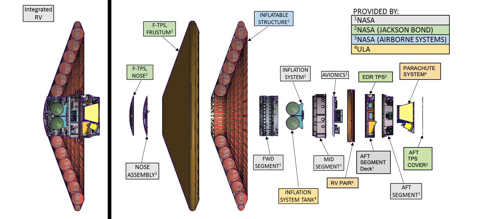
An example of a state-of-the-art spacecraft thermal protection system, based on an inflatable concept, is illustrated in the figure below. A further engineering challenge is that these re-entry environments cannot be easily simulated on Earth or fully modeled analytically under the expected combined mechanical and thermal loads. Hence, the design risks are higher than for an aircraft.
Airframe Weight Estimation
A key goal in flight vehicle design is to achieve maximum performance with the lowest structural weight and cost. For a given aircraft type, its price is roughly proportional to its empty weight. However, this goal is not always so readily obtained in practice. In this regard, “cost” includes both the vehicle’s acquisition cost (i.e., its “price”) and its operational costs. A flight vehicle comprises many parts, generally combined into major groups or sub-assemblies, such as wings, fuselage, tail, undercarriage, and propulsion system. Of course, the weight of a new aircraft design is never known a priori and must be obtained iteratively as an integral part of the design process.
For preliminary airframe design, weight estimates can be performed using historical data for existing aircraft, such as the approaches discussed by Ramer and the related approaches documented by Torenbeek and Roskam. As the design process is refined, which will inevitably include computer-aided design (CAD), finite element methods (FEM), and computational fluid dynamics (CFD), the estimated weight of components and sub-assemblies can be obtained with greater accuracy. The effects of weight on performance and cost can then be reassessed, and the structural design can be iteratively refined toward closure. It should be recognized that the weight of an airframe design generally increases disproportionately with size (i.e., the so-called “square-cube law“), posing a significant design challenge, particularly for commercial aircraft.
Advanced materials and sophisticated manufacturing techniques may reduce the required material and lower the airframe weight. The additional design time and tooling investments required to achieve significant airframe weight savings may result in a higher airplane useful weight (i.e., more fuel load and/or payload), but not necessarily a lower acquisition cost. Nevertheless, the long-term economics of higher payloads and lower operational costs for airliners are very attractive to an aircraft operator such as an airline.
What is the payload?
Payload refers to the weight,  , carried on the aircraft that pays the bills. The payload comprises the passengers, their baggage, and cargo. The useful load,
  , includes everything on board the aircraft that is not part of the aircraft’s empty weight,
  . The empty weight comprises the weight of the airframe, engines, and all necessary flight systems. Fuel is not a payload; it is part of the useful load. The useful weight, , therefore, is the sum of the payload weight, , and the fuel weight,
  , i.e.,
![\[ W_{U} = W_P + W_F \]](https://eaglepubs.erau.edu/app/uploads/quicklatex/quicklatex.com-13529fe1dcc5e66f2406a4184beb8c87_l3.svg "Rendered by QuickLaTeX.com")
The useful load and, hence, the payload weight can vary depending on the aircraft type, the intended purpose of the flight, the altitude at which the aircraft flies, and the flight distance. For most aircraft, the payload and fuel load can be traded off against each other, allowing for more payload to be carried with a lower fuel load. Payload is an essential consideration for airlines because they need to have as much payload as possible but also ensure that they take sufficient fuel for the flight and do not exceed the maximum certified gross takeoff weight,  , for any given aircraft, i.e.,
![\[ W_{E} + W_{U} = W_E + W_P + W_F \le W_{\rm \scriptsize MGTOW} \]](https://eaglepubs.erau.edu/app/uploads/quicklatex/quicklatex.com-cc4b89afe0da70bca31b41ca5de9924d_l3.svg "Rendered by QuickLaTeX.com")
Square-Cube Law in Structural Design
The square-cube law provides a fundamental constraint on how structures behave when scaled to different sizes. Consider any structural member that is enlarged or reduced uniformly by a linear factor  . If the original component has a characteristic length , then the scaled version has length
  . Cross-sectional areas scale with
  , while volumes and masses scale with
  . Because structural loads typically scale with weight or inertia, they also increase with . This reasoning is the origin of the so-called “square-cube” law in that the weight of a given design increases with the cube of its size as it is scaled up.
The square-cube law also applies to stresses. Let an original structural member have a cross-sectional area  and be subjected to a load
  . After scaling, the area becomes
(47) 
but the load becomes
(48) 
The resulting nominal stress, therefore, scales as
(49) 
Therefore, a geometrically similar structure becomes increasingly stressed as it increases in size, because the stresses increase in direct proportion to size while the material strength remains unchanged. Large structures must, therefore, be proportionally thicker or differently proportioned; otherwise, they will fail under the loads.
Buckling follows directly from the same law. The buckling load of a column scales as  . Because
  and
and  , the critical load scales as , yet the axial load from weight scales as . Consequently, the safety margin against buckling decreases as the structure becomes larger. Slender members that work well in small models often require significant stiffening, tapering, or material changes at larger scales.
These scaling relationships explain why larger airplanes and longer-span wings cannot maintain geometric similarity, both external and internal, with their smaller counterparts. Increased thickness, nonuniform reinforcement, and redesigned load paths are inevitable. The square-cube law is therefore a governing principle in structural engineering because the internal stress state does not scale in the same way as the geometric dimensions.
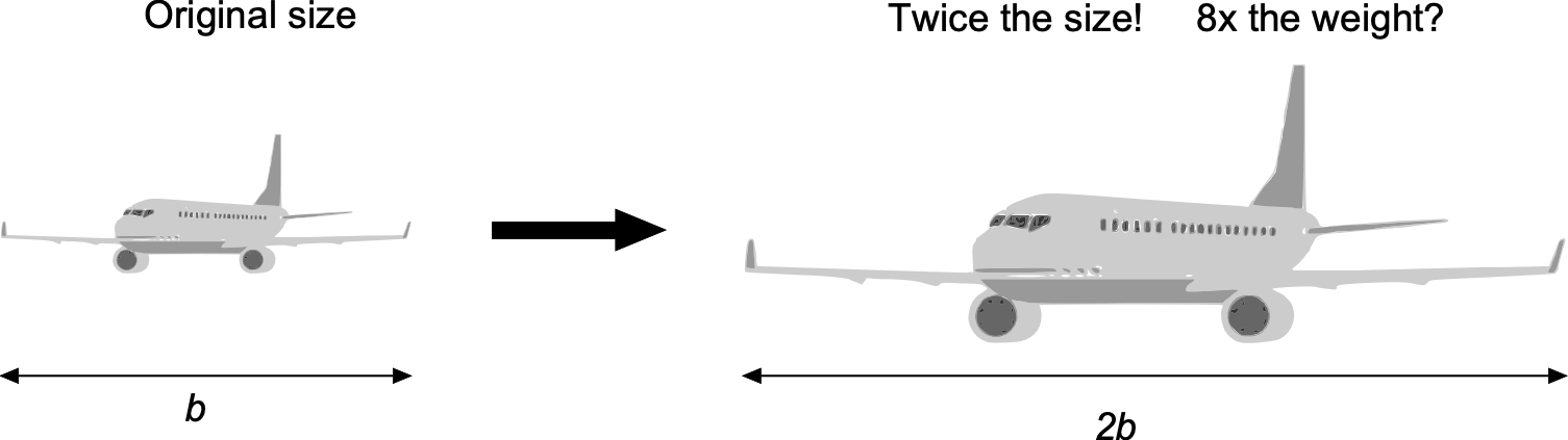
A practical illustration of the square-cube law in aircraft design occurred when Boeing scaled up the 707 into the far larger 747. The wing of the 747, for example, experienced bending moments that increased much faster than its geometric proportions, and the fuselage frames similarly faced rapidly growing loads. The designers could not simply increase the thickness of every component by the same proportion; otherwise, the airplane would have been far too heavy to fly. Entire load paths had to be redesigned to achieve higher strength-to-weight ratios, and sandwich construction materials were used for the first time. The transition from the 707 to the 747, therefore, demonstrated that large aircraft cannot be created by simply scaling up existing designs.
Spacecraft Structures
Many of the structural design challenges for spacecraft are similar to those for aircraft, including the need for high-strength-to-weight materials, thin-walled construction, and reliable, low-cost manufacturing. However, spacecraft must also withstand distinct loading environments. The primary structural design issues occur during launch, where the vehicle is subjected to intense acoustic loading, high accelerations, broadband engine-induced vibration, and short-duration applied shocks.
These conditions are usually represented through equivalent mechanical loads applied to the spacecraft’s structure. For example, the quasi-static portion of the launch environment is modeled as an effective inertial force, i.e.,
(50) 
where  is the component mass and
  is the design acceleration level specified by the launch vehicle. The fluctuating acoustic field is treated as a spatially distributed pressure with an effective root-mean-square value of
(51) 
where  is the acoustic pressure spectral density over the frequency band
  to
to  . This pressure excites skin panels and internal components through broadband loading. Vibration from engines and aerodynamic forcing is represented through a base-acceleration spectrum
  , which produces modal inertial forces proportional to the effective modal mass
  of each structural mode. Stage separation events are quantified using a Shock Response Spectrum, which provides the peak transient acceleration transmitted into brackets, mounts, and sensitive equipment. Together, these simplified representations capture the combined mechanical environment that typically governs the sizing of the primary spacecraft structure.
Once in orbit, the spacecraft experiences almost no aerodynamic loading but must endure extreme thermal gradients, long-duration creep and relaxation, and exposure to micrometeoroid and orbital-debris impacts. Consequently, spacecraft structures require a combination of high stiffness, good buckling performance, dimensional stability, and damage tolerance.
Most spacecraft are constructed from metallic materials such as aluminum-lithium alloys, titanium, and stainless steel, along with composite sandwich panels for decks, equipment bays, and solar array substrates. These materials combine high specific stiffness with predictable thermal-cycling behavior. As with airplanes, semi-monocoque construction is widely used for spacecraft, with skins, stringers, and frames arranged to resist axial, bending, and shear loads through efficient load paths. The photograph below shows a machined aluminum shell with a triangular isogrid pattern. Isogrid and orthogrid patterns are commonly used in launch vehicle interstages, satellite cylinders, and fairings because they provide excellent buckling resistance and stiffness while minimizing structural mass.
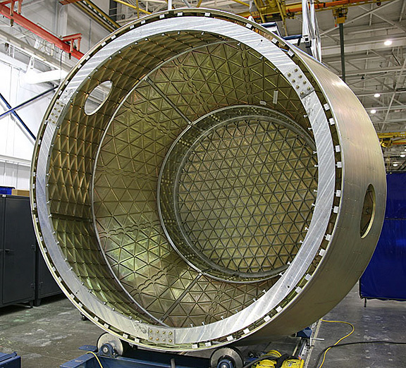
A significant challenge in designing launch vehicles is the structural design of the propellant tanks, which must operate as large pressure vessels, often filled with cryogenic liquids. For a thin-walled cylindrical tank under internal pressure  , the dominant membrane stresses depend on the tank radius
  and the wall thickness
  . The hoop and longitudinal membrane stresses are
(52) 
These relationships help explain why tank mass and structural strength demands grow with both radius and pressure. Cryogenic temperatures introduce additional structural issues, including thermal contraction and the embrittlement of some alloys. The thermal strain associated with a temperature change  can be modeled using
(53) 
where  is the coefficient of thermal expansion, so differential temperatures between tanks, feed lines, and supporting structures can cause large internal stresses. The most common cryogenic propellants include liquid hydrogen (LH2), liquid oxygen (LOX), and liquid methane (LCH4). Their storage tanks are fabricated from lightweight materials such as aluminum alloys, stainless steels, and advanced composites, and are equipped with multilayer insulation and vacuum jackets to minimize heat transfer. Hemispherical and cylindrical tank geometries promote uniform membrane stresses and delay buckling under internal pressure and bending loads.
Cryogenic tanks are essential components of major launch vehicles, including SpaceX’s Falcon 9 and NASA’s Space Launch System (SLS), as well as spacecraft intended for deep-space missions that require long-term propellant storage. An example of the liquid hydrogen tank used on NASA’s SLS rocket is shown below. This tank uses friction welding, a solid-state joining process in which a rotating tool softens the material without melting it. The stirred material forms a high-quality weld with low distortion and excellent mechanical properties, improving reliability in critical load-carrying joints. Composite overwrapped and all-composite cryogenic tanks are also being developed, although challenges remain with permeability, microcracking under thermal cycling, and long-term material compatibility with cryogenic propellants.
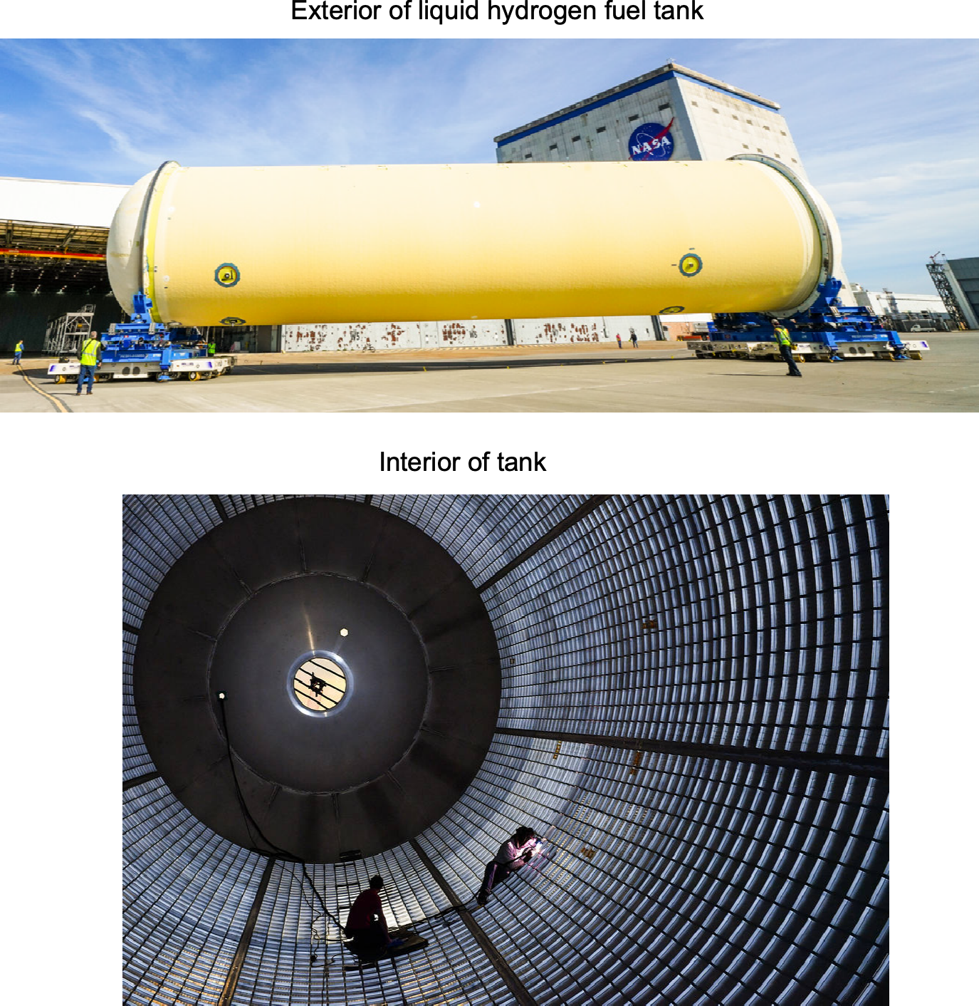
Managing boil-off gases and maintaining the low temperatures of cryogenic propellants are continuing engineering challenges. These are addressed through combinations of passive insulation and active cooling systems. Tanks incorporate feed lines, valves, vent systems, and health-monitoring sensors to maintain a controlled propellant supply to the engines. Pressure relief devices prevent over-pressurization, and internal baffles help reduce propellant slosh loads during ascent. In addition to structural strength, designers must ensure compatibility with vacuum environments, outgassing limits, and long-term dimensional stability under repeated thermal cycles.
Check Your Understanding #5 – Launch load effects on an equipment panel
A rectangular equipment panel on a small spacecraft measures 0.40 m × 0.30 m and is supported along all four edges. The panel is made from an aluminum alloy with a thickness of 2.0 mm and a yield strength of 250 MPa. An 18 kg avionics box is mounted near the center of the panel. During launch, the specified quasi-static acceleration is 5g, and the acoustic environment produces an RMS pressure of 3.0 kPa on the panel’s exposed face. Using g = 9.81 m/s², estimate: 1. The inertial load transmitted by the avionics box under the quasi-static acceleration; 2. The net acoustic force acting on the panel; 3. The maximum bending stress in the panel from the acoustic pressure, if modeled as a supported beam spanning 0.40 m; 4. Whether the acoustic loading is likely to cause the material holding the panel to reach its yield stress.
Show solution/hide solution.
(a) The quasi-static inertial load from the avionics box is
![\[ F_{\text{qs}} = m\,a_{\text{eff}} = 18 \times 5g \approx 8.8 \times 10^{2} \text{ N} \]](https://eaglepubs.erau.edu/app/uploads/quicklatex/quicklatex.com-721c8b403c5391ce6f78c843b9f1cacd_l3.svg "Rendered by QuickLaTeX.com")
(b) The panel area is
![\[ A = 0.40 \times 0.30 = 0.12 \text{ m}^2 \]](https://eaglepubs.erau.edu/app/uploads/quicklatex/quicklatex.com-be16ee5c10f53f98f2e93454829aed8f_l3.svg "Rendered by QuickLaTeX.com")
The net acoustic force is
![\[ F_{\text{ac}} = p_{\text{RMS}}\,A = 3.0 \times 10^{3} \times 0.12 \approx 3.6 \times 10^{2} \text{ N} \]](https://eaglepubs.erau.edu/app/uploads/quicklatex/quicklatex.com-1f8fbd41d9ca93aea697bf23eaae6c81_l3.svg "Rendered by QuickLaTeX.com")
(c) To estimate the stress, treat the panel as a supported beam of span  , width
  , and thickness
  . The distributed load is
![\[ q = p_{\text{RMS}}\,b = 3.0 \times 10^{3} \times 0.30 = 9.0 \times 10^{2} \text{ N/m} \]](https://eaglepubs.erau.edu/app/uploads/quicklatex/quicklatex.com-f6afec0cc6a3f12d46378171bfa9a445_l3.svg "Rendered by QuickLaTeX.com")
The maximum bending moment is
![\[ M_{\max} = \frac{q L^{2}}{8} \approx 18 \text{ N m} \]](https://eaglepubs.erau.edu/app/uploads/quicklatex/quicklatex.com-997bb041cb7774961a159c9423601ed0_l3.svg "Rendered by QuickLaTeX.com")
The second moment of area is
![\[ I = \frac{b t^{3}}{12} = \frac{0.30 \times (0.002)^{3}}{12} = 2.0 \times 10^{-10} \text{ m}^{4} \]](https://eaglepubs.erau.edu/app/uploads/quicklatex/quicklatex.com-7d77507d19e7e5b5dcc966d586181c65_l3.svg "Rendered by QuickLaTeX.com")
The bending stress is
![\[ \sigma_{\max} = \frac{M_{\max} (t/2)}{I} \approx 9.0 \times 10^{7} \text{ Pa} = 90 \text{ MPa} \]](https://eaglepubs.erau.edu/app/uploads/quicklatex/quicklatex.com-35ddb94cdf61425e0e4b1a29a21410f1_l3.svg "Rendered by QuickLaTeX.com")
(d) Because 90 MPa is well below the yield strength of 250 MPa, the panel does not yield under the acoustic loading. The inertial load from the mounted equipment is larger than the net acoustic force, while the panel’s stress response is governed by bending stiffness.
Summary & Closure
Aerospace structures require a unique combination of strength and lightness. The finite element method (FEM) is widely used to design structures that meet specific requirements while minimizing weight. Stressed skin structures made of aluminum alloys have been the dominant material for aerospace applications for many years, providing the necessary strength and durability for most aircraft and spacecraft. However, composite materials, such as carbon fiber-reinforced polymers, have gained increasing popularity in recent years, particularly for primary structures like wings and fuselages. Using composites offers improved strength-to-weight ratios and greater structural design flexibility, making them an excellent alternative to aluminum alloys in many aerospace applications.
The design of spacecraft structures parallels that of aircraft in many ways. Advanced materials and fabrication techniques, such as carbon fiber composites and friction stir welding, are employed to achieve high strength-to-weight ratios. Spacecraft structures designed for cryogenic applications present unique technical challenges, as they must store and manage cryogenic propellants at extremely low temperatures, such as liquid hydrogen and oxygen. The design and engineering of spacecraft structures are critical to mission success, ensuring reliability and durability while optimizing for weight and efficiency.
5-Question Self-Assessment Quickquiz
For Further Thought or Discussion
- List some of the relative advantages of wood and fabric airplane construction versus stressed metallic skin construction.
- Research the manufacturing methods of making airplanes using conventional riveted construction.
- What are the primary potential failure modes in aerospace structures, and how are they mitigated in design and manufacturing?
- What are the fundamental differences between aerospace structures and structures in other engineering disciplines?
- Discuss the challenges and considerations in designing flight vehicle structures for supersonic and hypersonic flight.
Other Useful Online Resources
To learn more about flight vehicle structures, try some of these online resources:
- Video lecture on aircraft structures and loads applied to an airframe.
- A short video explaining wooden airframe structures and the selection of the wood.
- Great video lecture on aerospace structures: Airframe Basics.
- Test your knowledge of the construction of an aircraft: Engineering a Jetliner.
- Lecture series on advanced aircraft structures by Dr. Goyal.
- Learn how to buck a solid rivet for an airplane structure.
- Aircraft conversion XXL – A cargo plane is born.
- The author is grateful to his structures teacher, Professor Henry Wong. He was an engineer for the Armstrong Siddeley Company, the Hunting Percival Aircraft Company, and the de Havilland Aircraft Company. Dr. Wong worked on investigations into the De Havilland Comet airliner crashes, during which significant advances were made in understanding metal fatigue. He was a Professor of Aeronautics and Fluid Mechanics at the University of Glasgow from 1960 to 1987. ↵
- A two-force member is a structural element in which the applied loads act only at its two ends, with no intermediate loads. Under these conditions, the member can carry only a single axial force, either tension or compression, and the internal force is constant along its entire length. Bending moments and shear forces cannot exist in a two-force member. ↵
