25 Domain Name System Part 3 – Dynamic DNS
Jacob Christensen
In Chapter 23, we manually configured our DNS entries with the IP addresses that were statically assigned to our client devices. However, it is uncommon to use static IP assignments, especially in networks with hundreds or even thousands of clients! If we can get our DHCP and ADNS servers to communicate with each other, then IPs can automatically be assigned and our zone files can automatically be populated. This practice is called Dynamic DNS (DDNS).
This lab will expand on the work in Chapter 23 and Chapter 24 to learn how to configure and manage DDNS in a small network environment.
Estimated time for completion: 45 minutes
learning objectives
- Learn how DDNS works on an enterprise network
- Learn how to work with multiple services (DHCP and DNS) on one network
prerequisites
deliverables
- Four (4) screenshots
- BLUE1 (PC1) successfully pinging BLUE2 (PC2) by name
- BLUE2 (PC2) successfully pinging BLUE3 (PC3) by name
- BLUE1 (PC1) successfully performing a DNS query and resolution with the NS1 server via Wireshark monitoring
- Live stream of NS1 reports of the DHCP handshake and zone logs when (BLUE3) PC3 is rebooted
resources
- BIND9 Administrator Reference Manual – https://bind9.readthedocs.io/en/v9.18.16/
- MikroTik RouterOS Documentation – https://help.mikrotik.com/docs/display/ROS/RouterOS
- Archy’s Blog – Dynamic DNS with BIND and ISC-DHCP – https://archyslife.blogspot.com/2018/02/dynamic-dns-with-bind-and-isc-dhcp.html
- Configuring Dynamic DNS with BIND9 – https://doncrawley.com/soundtraining.net/files/configuringdynamicdnswithbind9.pdf
Contributors and testers
Mathew J. Heath Van Horn, PhD, ERAU-Prescott
Kyle Wheaton, Cybersecurity Student, ERAU-Prescott
Phase I – Building the Network Topology
This lab is an extension of the previous two chapters. If you have not completed them yet, it is recommended that you do so first before continuing. By the end your network should look like the following:
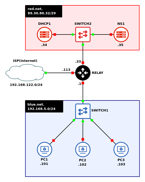
- Preliminary step in VirtualBox
- Create/clone a fresh copy of the Linux Server VM with ISC’s DHCP server installed
- Start GNS3
- Save the previous lab as a new project: LAB_11
- Reuse the network that you built in the previous chapter
- Configure the router to act as a DHCP relay for the Blue subnet (Chapter 21, Phase II, Step 1)
- Add a DHCP server to the Red network – Ubuntu server (DHCP1)
NOTE: In reality, both the DHCP and DNS services can operate from the same machine; however, we are splitting them into two separate devices for clarity.
- Add a switch to the Red network – Ethernet switch
- Connect NS1 and DHCP1 to the switch so that they are on the same LAN
- Remove the static IP addresses from Tiny Core Linux clients by commenting out the rules for static IP assignment
> vi /opt/bootlocal.sh

Figure 1a – removing the static IP NOTE: Make sure that each client device keeps its unique hostnames!
- Label and organize your network as necessary
Phase II – Modify the DNS Server
This section assumes that all configurations made in the previous chapter have carried over to this one.
- Start NS1 and login
- Generate a new Remote Name Daemon Control (RNDC) key to use to communicate with DHCP1
NOTE: Ensure that you have the bind9-utils package installed!
> rndc-confgen -a -b 512
Switch Description -a Automatically generate the RNDC file in the /etc/bind directory. -b Set the size of the key as a value between 1 and 512 bits. - Modify the file permissions of rndc[.]key
- Change the owner and group from root to the bind user
> chown bind:bind /etc/bind/rndc.key
- Change the file permissions to give read access for the group
> chmod 640 /etc/bind/rndc.key
- Change the owner and group from root to the bind user
- Modify the named[.]conf[.]local file
> vi /etc/bind/named.conf.local
- At the beginning of the file, before the zone declarations, include the RNDC key
include “/etc/bind/rndc.key”;

Figure 2 – BIND9 configuration - Within each zone declaration, add the following directive to allow the zones to be updated with the key
allow-update { key rndc-key; };
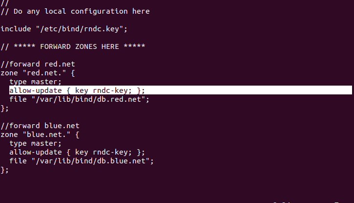
Figure 3 – Updating zone directives - Save and exit the editor
- Verify the configuration settings
> named-checkconf
- At the beginning of the file, before the zone declarations, include the RNDC key
- Add a new static entry in the red[.]net zone files for DHCP1
- Modify the forward lookup zone file
> vi /var/lib/bind/db.red.net
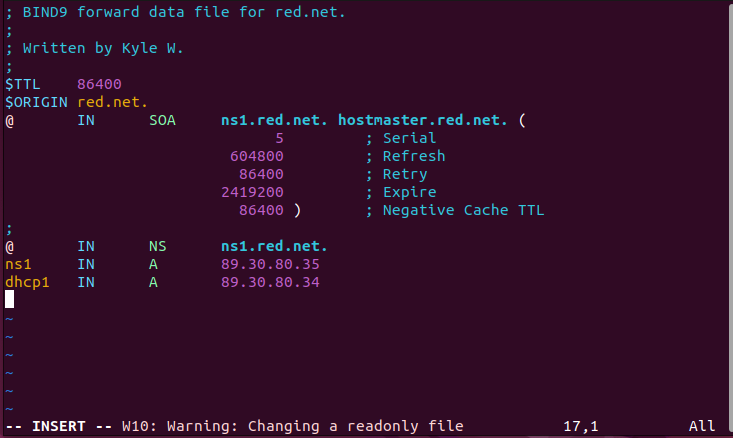
Figure 4 – Updating static forward DNS entry - Modify the reverse lookup zone file
> vi /var/lib/bind/db.red.net.rev
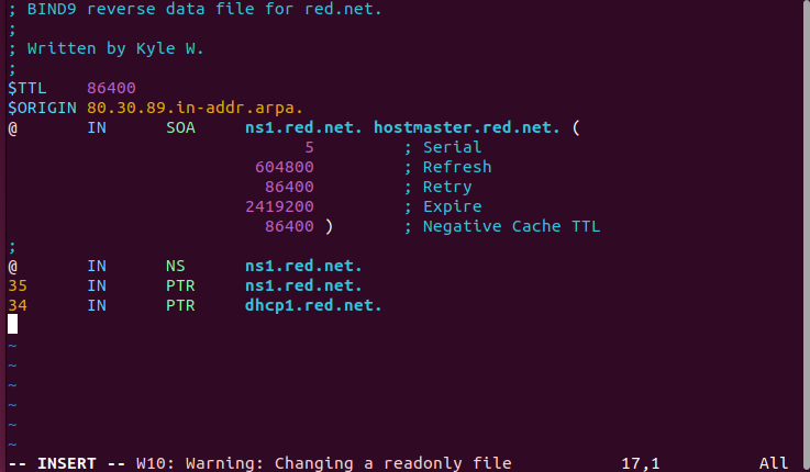
Figure 5 – Updating static reverse DNS entry
- Modify the forward lookup zone file
- Remove all client static entries in the blue[.]net zone files
- Modify the forward lookup zone file
> vi /var/lib/bind/db.blue.net
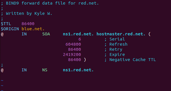
Figure 6 – Purging static forward DNS entries for an internal subnet - Modify the reverse lookup zone file
> vi /var/lib/bind/db.blue.net.rev
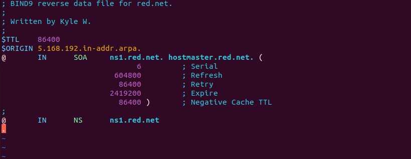
Figure 7 – Purging static reverse DNS entries for an internal subnet
- Modify the forward lookup zone file
- Restart the DNS server and verify that it is running
> systemctl restart named.service
> systemctl status named.service
NOTE: Errors at this stage are likely due to incorrect permissions on the RNDC file. Ensure that both the owner (bind) and group (bind) can read the file.
- Start and enable Systemd’s time synchronization daemon
> systemctl start systemd-timesyncd.service
> systemctl enable systemd-timesyncd.service
Phase III – Configuring the DHCP Server
The following section outlines the configuration of the DHCP daemon for the network.
- Start DHCP1 and login – Refer to (Chapter 23, Phase III, Step 3)
- Modify the machine’s hostname to dhcp1
> hostnamectl hostname dhcp1
- Assign a static IP address, default gateway, primary DNS server, and local domain name
NOTE: This example uses the following information:
– IP Address: 89.30.80.34/29
– Local Domain: red.net
– Nameservers: 89.30.80.35
– Gateway: 89.30.80.33- Verify that the name server information is correctly pointing towards ns1 (89.30.80.35) and that the current domain is red[.]net
> resolvectl status

Figure 8 – DNS information verification
- Verify that the name server information is correctly pointing towards ns1 (89.30.80.35) and that the current domain is red[.]net
- Modify the machine’s hostname to dhcp1
- Having all elements in a network synchronized to the same time is critical. SNTP clients provide this service. Linux uses Systemd’s timesync daemon to provide SNTP packets. Start it and enable (start on boot) the service by typing
> systemctl start systemd-timesyncd.service
> systemctl enable systemd-timesyncd.service
- Transfer the RNDC key file from NS1 to the primary user’s home directory in DHCP1
NOTE: The default user on my machines is iako; be sure to change the following commands as necessary.
- Login to the NS1 terminal
> ssh iako@89.30.80.35
NOTE: You should see the hostname change to ns1 when you login successfully.
- Switch to the root user
> sudo su
- Use the Secure Copy (SCP) command to make a copy of rndc[.]key to the primary user of DHCP1
> scp /etc/bind/rndc.key iako@89.30.80.34:/home/iako
- Exit from root
> exit
- Exit the SSH session
> exit
- Verify you see the RNDC key in your home directory
> ls -l ~
- Login to the NS1 terminal
- Modify the permissions for the RNDC key file
- Ensure that the owner and group are both root
> chown root:root ~/rndc.key
- Change the permissions to remove read access from others
> chmod 640 ~/rndc.key
- Move the file to the DHCP configuration directory
> mv ~/rndc.key /etc/dhcp/ddns-keys
NOTE: If the ddns-keys folder does not exist, make it with the following permissions:
> mkdir /etc/dhcp/ddns-keys
> chown root:dhcpd /etc/dhcp/ddns-keys
> chmod 710 /etc/dhcp/ddns-keys
- Ensure that the owner and group are both root
- Modify the DHCP daemon configuration file to support both subnets and their domains
> vi /etc/dhcp/dhcpd.conf
- Include global parameters that apply to all subnets, including the new RNDC key file
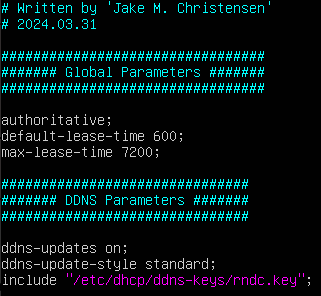
Figure 9 – DHCP daemon configuration part 1 - Add the forward lookup zones for the subnets included in our BIND9 server
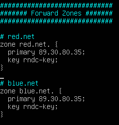
Figure 10 – DHCP daemon configuration part 2 - Add the reverse lookup zones for the subnets included in our BIND9 server
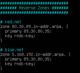
Figure 11 – DHCP daemon configuration part 3 - Add the DHCP subnet directives for both the Red and Blue networks
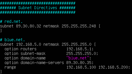
Figure 12 – DHCP daemon configuration part 4
- Include global parameters that apply to all subnets, including the new RNDC key file
- Restart the DHCP service
- Ensure that each client in blue[.]net is able to receive an IP address and that its domain information is correct
- Login to the terminal of PC1
- Verify it was assigned an IP address
> ifconfig
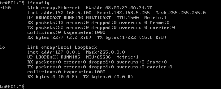
Figure 13 – Tiny Core static IP verification - Verify its DNS information is correct
> cat /etc/resolv.conf

Figure 14 – DNS information verification - Repeat for the other two client devices
- Troubleshoot as necessary before proceeding to the next section
- Transfer the RNDC key file from NS1 to the primary user’s home directory in DHCP1
Phase IV – Wireshark Captures
Now that our network is set up, lets watch at some live packet captures to what DNS queries look like in action.
- Start a Wireshark capture between NS1 and the switch
- Test the dynamic DNS updates
- In Wireshark, filter for DNS
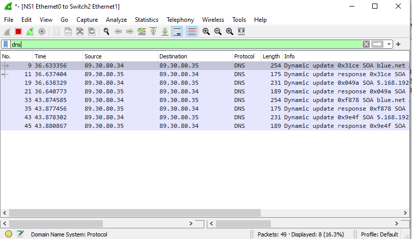
Figure 15 – DNS traffic - In the NS1 terminal, start monitoring the system log
> tail -f /var/log/syslog
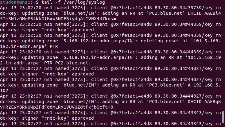
Figure 16 – Live monitoring system logs - Reboot PC1 and watch the logs for the DHCP handshake and zone file mapping

Figure 17 – Dynamic DNS updates - In the Wireshark window, you should see *DNS Update* packets
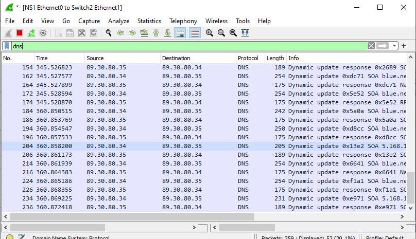
Figure 18 – Wireshark DNS updates - Repeat for the other two PC clients
NOTE: You can request new IP address leases in Tiny Core with the following command:
> sudo udhcpc
- In Wireshark, filter for DNS
- After about 15 minutes, BIND9 will populate the db files with the updated host/IP records
NOTE: By default, this information is stored in a journal file (.JNL) which is located in the same directory as the zone files. The main database files are not frequently updated to increase efficiency.
End of Lab
Deliverables
4 screenshots are needed to receive credit for this exercise:
- BLUE1 (PC1) successfully pinging BLUE2 (PC2) by name as observed on BLUE1 (PC1)
- BLUE2 (PC2) successfully pinging BLUE3 (PC3) by name as observed on BLUE2 (PC2)
- BLUE1 (PC1) successfully performing a DNS query and resolution with the NS1 server via Wireshark monitoring
- Live stream of NS1 reports of the DHCP handshake and zone logs when (BLUE3) PC3 is rebooted
Homeworks
Assignment 1 – Add the GREEN network to the workspace on the existing router
- Minimize wasted address space for 313 machines
- Add 3 Tiny Core machines to prove functionality
- It is okay to turn off the 3 BLUE end devices to save VM resources
- Modify the router, DHCP1, and NS1 to provide the same functionality to the GREEN network that exists on the BLUE network
Assignment 2 – Complete Assignment 1 and then add a PURPLE network
- Minimize wasted address space for 512 machines
- Add 3 Tiny Core machines to prove functionality
- It is okay to turn off the other end devices to save VM resources
- Modify the router, DHCP1, and NS1 to provide the same functionality to the PURPLE network that exists on the BLUE and GREEN networks
RECOMMENDED GRADING CRITERIA: Same as deliverables with appropriate substitutions for added devices.

