31 Network Hardening – pfSense Intranet
Mathew J. Heath Van Horn, PhD and Jacob Christensen
This chapter walks the learner through the steps needed to add a pfSense server to an enterprise network. Specifically, we are going to set up the lab, configure the pfSense server to act as our DHCP server, open all the firewall ports so you can see what is going on in the network, and then watch how the addition of each firewall rule affects our enterprise network.
Learning Objectives
- Configure pfSense for first use in GNS3
- Create various firewall rules to regulate IPv4 traffic
- Use pfSense as the DHCP server
- Use Wireshark to observe the effects of firewall rules
Prerequisites
- Chapter 6 – Adding a Virtual Machine to GNS3
- Chapter 10 – Create a pfSense Server
- Chapter 11 – Create a Ubuntu Desktop
Deliverables
- Screenshot of GNS3 Working environment once everything works
- Screenshot of the pfSense Dashboard
- Screenshot of all inside devices being able to ping
- Screenshot of the 3 rules for the DMZ
Resources
- We consolidated information from a wide variety of resources. However, three sources stand out as being particularly helpful to this lab and we want to recognize them here:
- Saifudeen Sidheeq – “How to Configure PfSense DMZ Setup? | Step by Step” – https://getlabsdone.com/how-to-configure-pfsense-dmz-setup/
- Frank at WunderTech – “How to Set Up a DMZ in pfSense” – https://www.wundertech.net/how-to-set-up-a-dmz-in-pfsense/
- Nikhath K – “pFSense DMZ Setup Guide” – https://bobcares.com/blog/pfsense-dmz-setup/
Contributors and Testers
- Julian H. Romano, Cybersecurity Student, ERAU-Prescott
- Dante Rocca, Cybersecurity Student, ERAU-Prescott
- Jungsoo Noh, Cybersecurity Student, ERAU-Prescott
Phase I – Setting up the Lab
The following steps are to create a baseline environment for completing the lab. It makes assumptions about learner knowledge from completing previous labs.
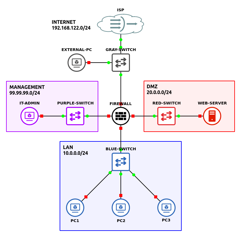
The completed network topology will look like this:
- In VirtualBox, create clones of your pfSense firewall and your Ubuntu Linux Desktop
NOTE: When importing new VMs into GNS3, ensure that Allow GNS3 to use any configured VirtualBox adapter is selected in their network settings!
- Start GNS3
- Import the devices
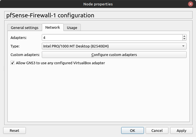
- On the pfSense Server, change the network settings to accommodate 4 adapters (Figure 2)
- Create a new project: LAB_16
- Build the following network:
Figure 3 – GNS3 workspace - “Internet”: (NO BOX) – 192.168.122.0/24
- One switch – Ethernet switch
- Internet connectivity with host machine – NAT Cloud (ISP)
- One client machine – Guest/VM with browser (external pc)
NOTE: While this example uses GNS3’s Chromium appliance, any device that has a browser installed will suffice.
- Management: (PURPLE BOX) – 99.99.99.0/24
- One switch – Ethernet switch
- One client machine – Guest/VM with browser (it admin)
- DMZ: (RED BOX) – 20.0.0.0/24
- One switch – Ethernet switch
- One client machine – Ubuntu Server (webserver)
NOTE: Ensure that the Apache2 package is installed.
> apt update
> apt install apache2
Since this lab isn’t focused on configuring a real webserver, we will simply use the default webpage that Apache provides out of the box. For now, simply verify that the daemon is running:
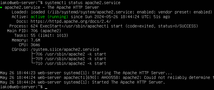
Figure 4 – Apache2 daemon status If you are having issues with getting Ubuntu or Apache to work, you can “simulate” a webserver with a VPCS client. The idea is to have an end device in the DMZ that we can ping from other areas on the network.
- LAN: (BLUE BOX) – 10.0.0.0/24
- One switch – Ethernet switch
- Three client machines – VPCS
- pfSense Firewall connections:
NOTE: This example uses the version 2.7.0 of pfSense Community Edition. You can either host this device as a VirtualBox VM or as a GNS3 appliance.
- Connect ethernet0 to the ISP switch (Internet)
- Connect ethernet1 to the Management switch
- Connect ethernet2 to the DMZ switch
- Connect ethernet3 to the LAN switch
- “Internet”: (NO BOX) – 192.168.122.0/24
Phase II – Configuring pfSense via CLI Console
Using VirtualBox instead of a physical box has its unique challenges. Mostly VirtualBox tries to help us do what we are trying to do and that can cause us some conflicts. We can work around these issues, but it may stress your cyber knowledge!
- In GNS3, start the pfSense server
NOTE: There are like 3 seconds where you can change your boot options, but just let the timer click down and let it boot. The first time it starts can take a few minutes.

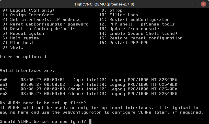
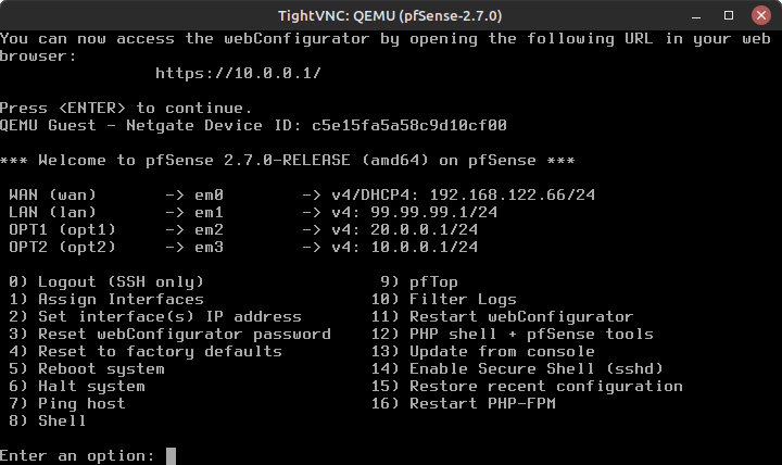
- Once the VM finishes booting, you should see the CLI menu below
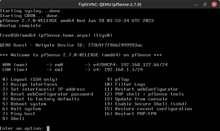
Figure 5 – pfSense command line console
- Once the VM finishes booting, you should see the CLI menu below
- As you can see, pfSense only recognizes two interfaces – em0 (WAN) and em1 (LAN) – as currently active
- Assign each of the pfSense interfaces on this device with a network
NOTE: Use the table below as a configuration guide for this step.
GNS3 Interface pfSense Interface pfSense Interface Name Ethernet0 em0 WAN Ethernet1 em1 LAN Ethernet2 em2 OPT1 Ethernet4 em3 OPT2 - Select option 1 to Assign Interfaces (Figure 6)
- When prompted – Should VLANs be set up now [y|n]? – type
n
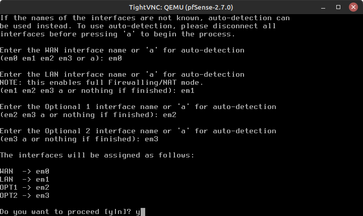
- Enter the WAN interface name or ‘a’ for auto-detection
em0
- Enter the LAN interface name…
em1
- Similarly, use em2 for the Optional 1 (OPT1) and em3 for the Optional 2 (OPT2)
- Verify the settings and type y to proceed (Figure 7)
- When prompted – Should VLANs be set up now [y|n]? – type
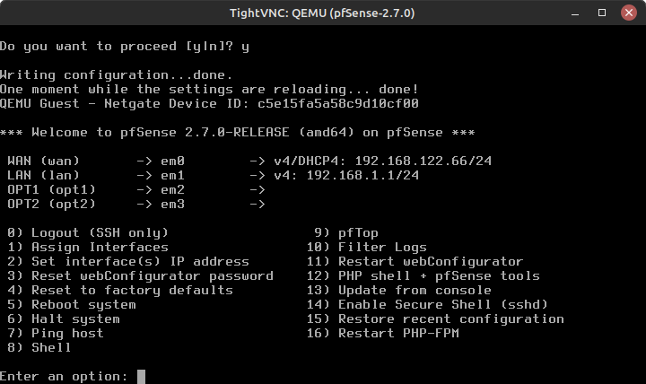
- You can see that all interfaces are now correctly assigned and active (Figure 8)
- Assign each of the pfSense interfaces on this device with a network
- Configure IP and DHCP settings
- Select option 2 to Set interface(s) IP address
- You will see a menu of the 4 interfaces with their current network settings (Figure 8)
NOTE: We will walk you through the first two interfaces, and leave the rest for you to complete on your own. Use the table below to assist with configuration settings.
pfSense Interface pfSense Interface IPv4 Address em0 WAN Dynamic – DHCP em1 LAN Static – 20.2.2.1/24 em2 OPT1 Static – 10.1.1.1/24 em3 OPT2 Static – 212.10.10.1/24 - Select interface 1 – WAN
- Configure IPv4 address WAN interface via DHCP? (y/n)
y
- Configure IPv6 address WAN interface via DHCP6? (y/n)
n
- Enter the new WAN IPv6 address
Press Enter for none (we are not using IPv6) - Do you want to revert to HTTP as the webConfigurator protocol? (y/n)
n
- Press Enter to finish em0 configuration and proceed
- Configure IPv4 address WAN interface via DHCP? (y/n)
- Select interface 2 – LAN
- Configure IPv4 address LAN interface via DHCP?
n
- Enter the new LAN IPv4 address
99.99.99.1/24
- Enter the new LAN IPv4 upstream gateway address
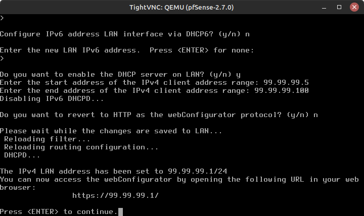
Press Enter for none - Configure IPv6 address LAN interface via DHCP6? (y/n)
n
- Enter the new WAN IPv6 address
Press Enter for none (we are not using IPv6) - Do you want to enable the DHCP server on LAN? (y/n)
y
- Enter the start address of the IPv4 client address range:
99.99.99.5
- Enter the end address of the IPv4 client address range:
99.99.99.100
- Do you want to revert to HTTP as the webConfigurator protocol?
n
- You should get a message on how to access the Web Configurator and be instructed to press Enter to continue (Figure 10)
- Configure IPv4 address LAN interface via DHCP?
- Setup em2 (OPT1), and em3 (OPT2) in a similar fashion as em1 using the IP address spaces we picked earlier (Figure 11)
- In GNS3, start the desktop in the Management LAN and check the current network settings
- Verify that DHCP works and that our management PC has an IP address in the range of 99.99.99.5 – 99.99.99.100
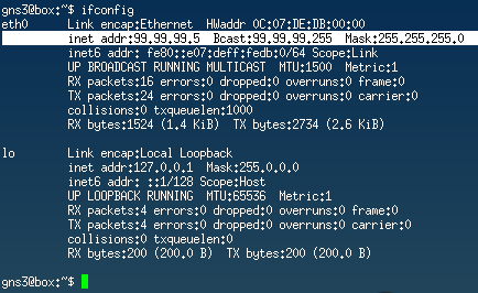
Figure 12 – Client network settings verified NOTE: You can request a new IP address at any time with the following commands (some Linux distros may vary…)
Release the currently assigned address on the interface named enp0s3.
> dhclient -r -i enp0s3 -v
Broadcast DHCP Discover packets to assign a new address.
> dhclient -i enp0s3 -v
- Open Firefox and type the IP address you were given for webConfigurator (it should be https://99.99.99.1/)
We haven’t set up any certificates yet, so you will get a big warning. Just click Advanced… and go to the site anyway by accepting the risk and continuing. This will take you to the pfSense GUI interface to Sign In. Previously, when you were asked to revert to HTTP, if you said y, you will not get any warnings. Great choice to avoid a security message, but bad practice because everything you do can be read by others monitoring your network traffic.
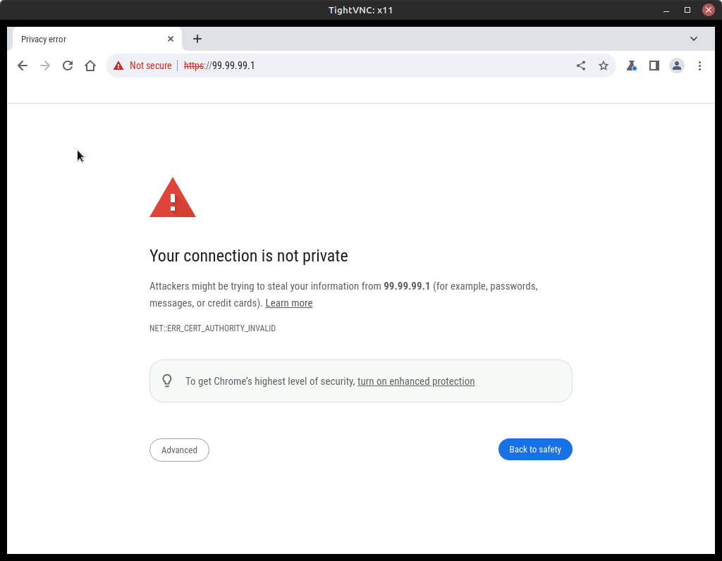
Figure 13 – Caution page connecting to pfSense
- Verify that DHCP works and that our management PC has an IP address in the range of 99.99.99.5 – 99.99.99.100
- Return to the GNS3 workspace, start the other devices in the DMZ and LAN spaces, and verify they are receiving IP addresses
NOTE: If a PC doesn’t get a DHCP IP, don’t worry about it, we’ll address it later using the GUI.
Phase III – Configuring pfSense via GUI Console
pfSense is not generally configured using the CLI menu. The GUI interface provides much more options and is easier to work with. At this point, all of your devices should be getting IP addresses from the pfSense DHCP server. If they aren’t getting a DHCP IP address, don’t worry, we’ll check them in the GUI.
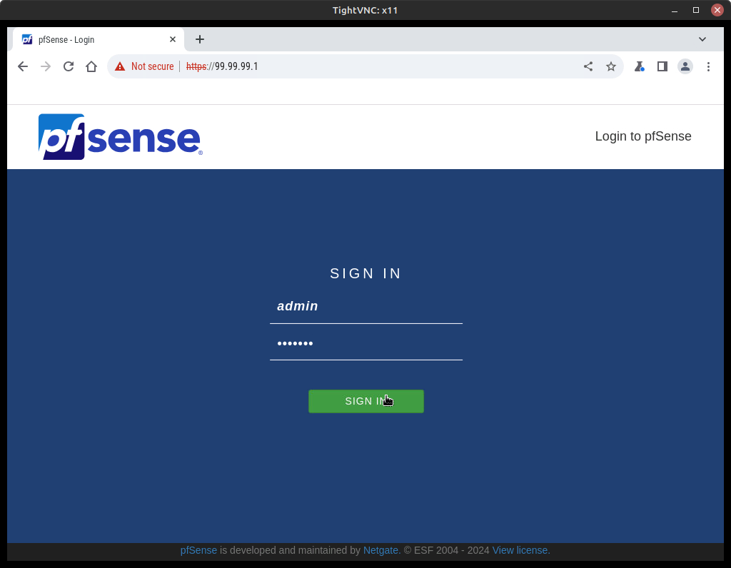
- On the Management PC, return to the login page at https://99.99.99.1 (Figure 14)
- At the Sign In screen use the default creds to log in:
Username: admin
Password: pfsense
- At the Sign In screen use the default creds to log in:
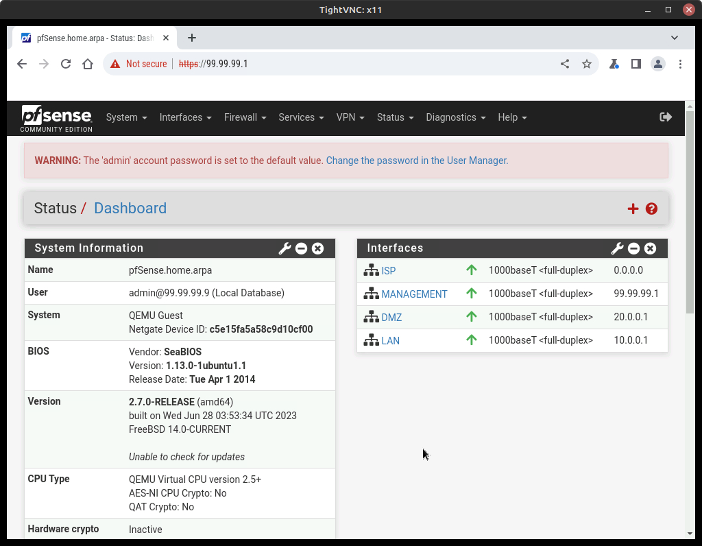
- Once logged in, on the top ribbon menu select Status–>Dashboard (Figure 15)
NOTE: At the top, you will see a large warning about using the default username and password. Normally I would say change this, but I’ve had too many students ask me, “Dr. HVH? What’s my password?” so please leave this alone for this exercise. On the right, you can see the interface settings we made earlier. I recommend that you click on these to get an idea of how the GUI and CLI commands line up but do not make any changes.
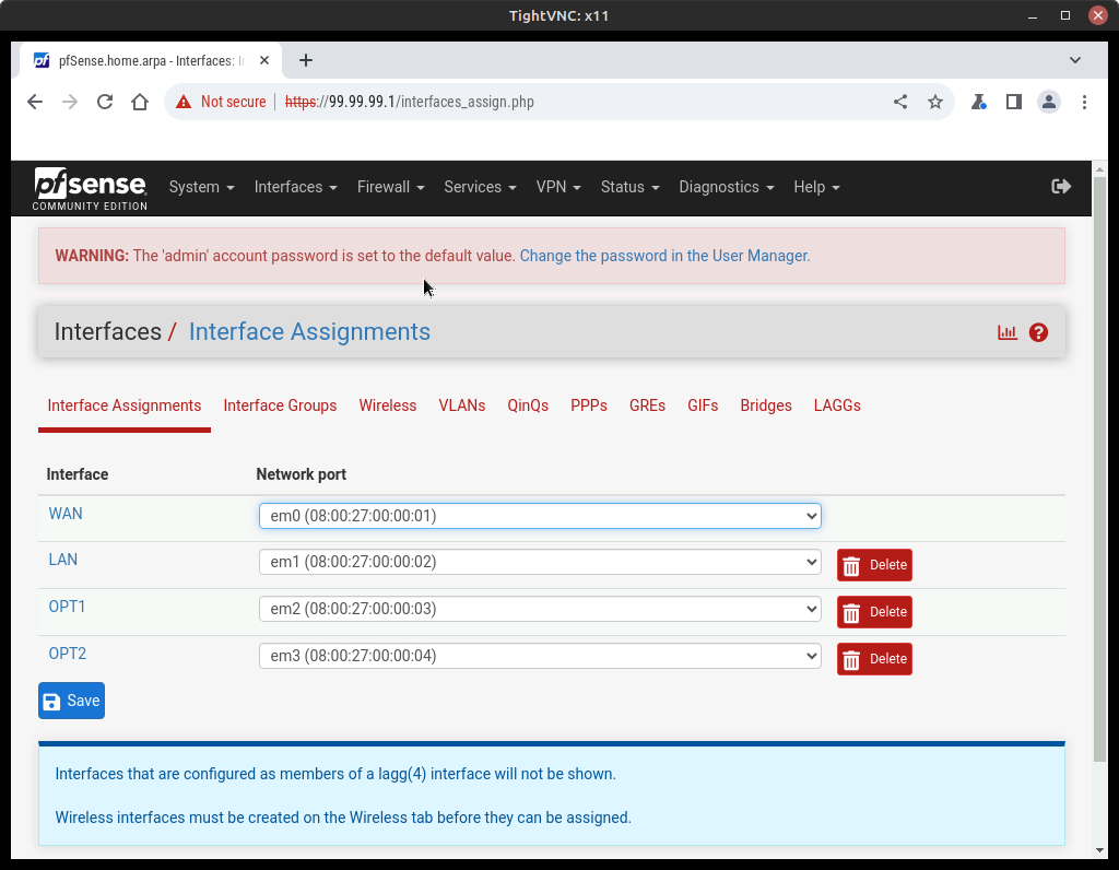
- At the top menu bar, select Interfaces–>Assignments (Figure 16)
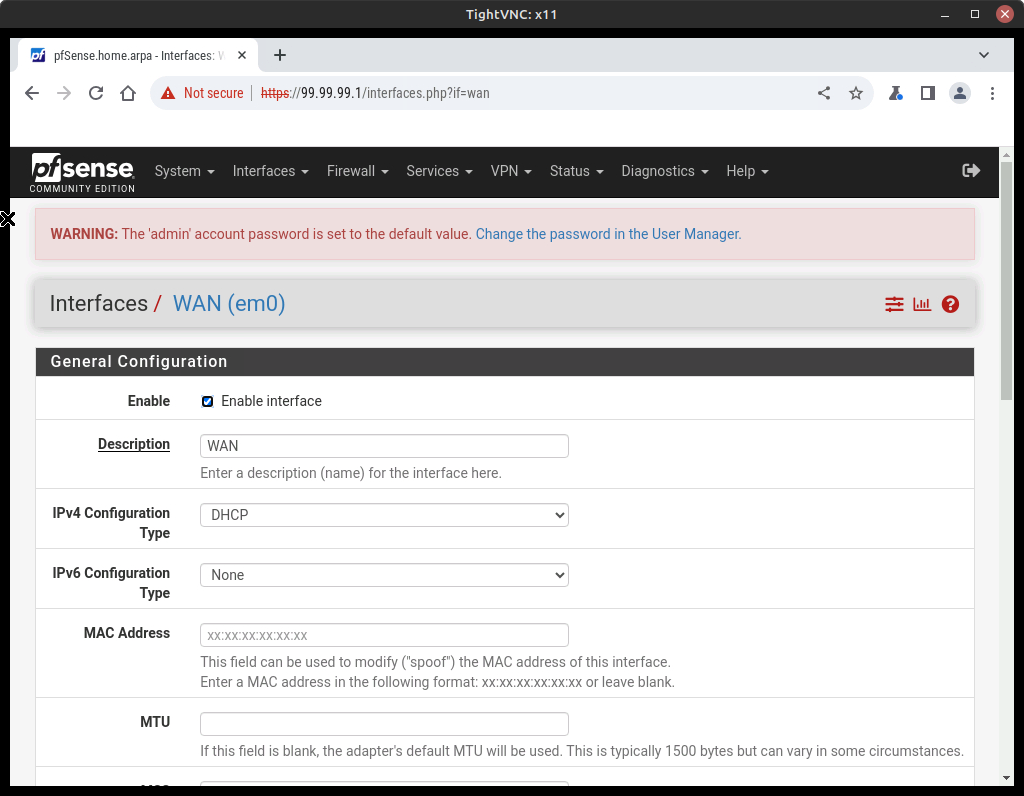
- Click on WAN to bring up the configuration settings for just that interface (Figure 17)
- Review the various options to get familiar with the available options
- Make the following changes as necessary
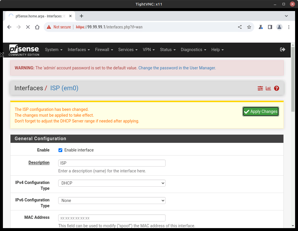
Option Value Description ISP IPv4 Configuration Type DHCP IPv6 Configuration Type None - Scroll to the bottom and press Save
- Now you will see a double-check prompt, so select Apply Changes (Figure 18)
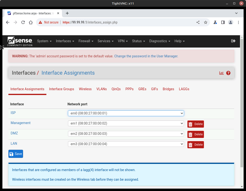
- Return to the Interface Assignments page and make the following adjustments to the remain adapters (Figure 19):
- LAN – change to “Management” and verify static IP assignment of 99.99.99.1/24
- OPT1 – change to “DMZ” and verify static IP assignment of 20.0.0.1/24
- OPT2 – change to “LAN” and verify static IP assignment of 10.0.0.1/24
NOTE: Yes, we could have assigned LAN to em3 from the get-go. However, by doing it this way, you gain experience in using the GUI. You will encounter a few of these moments in these labs. The goal is to help you learn, not just read and click.
- Click on WAN to bring up the configuration settings for just that interface (Figure 17)
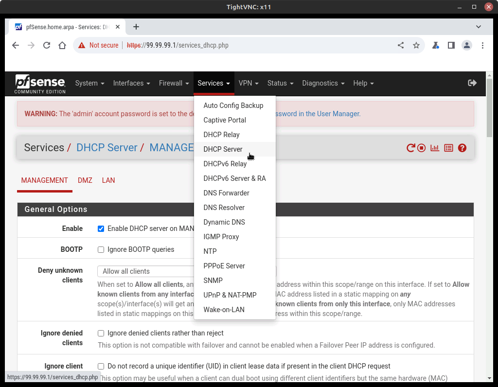
- Select Services –>DHCP Server to open the DHCP settings (Figure 20)
- View the details for the DHCP services on the Management interface
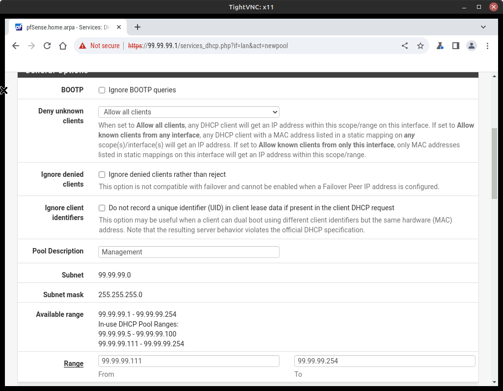
- Let’s pretend that we have reserved the IP addresses 99.99.99.101-99.99.99.110 so we will add a DHCP pool to use the remaining IP address
- Click on + Add Pool
- Pool Description –> “Management”
- Range –> 99.99.99.111 to 99.99.99.254
- Click on save
- Your settings should look like (Figure 21)
- Verify DHCP services for the ISP, DMZ, and LAN networks and change as necessary
NOTE: Remember that all DHCP servers need to provide a gateway address to their clients too.
- Return to the Dashboard by selecting Status –>Dashboard
Phase IV – Open Everything Up
In a default two-interface LAN and WAN configuration, pfSense software utilizes default deny on the WAN and default allow on the LAN. Everything inbound from the Internet is denied, and everything out to the Internet from the LAN is permitted. All home-grade routers use this methodology, as do all similar open-source projects and most similar commercial offerings. It’s what most people expect out of the box, therefore it is the default configuration. That said, while it is a convenient way to start, it is not the recommended means of long-term operation. – (Last accessed 25 October 2023 https://docs.netgate.com/pfsense/en/latest/firewall/best-practices.html )
We are going to violate these settings for demonstration purposes. Don’t worry, we’ll put them back.
- Navigate to the pfSense top ribbon and select Firewall–>Rules
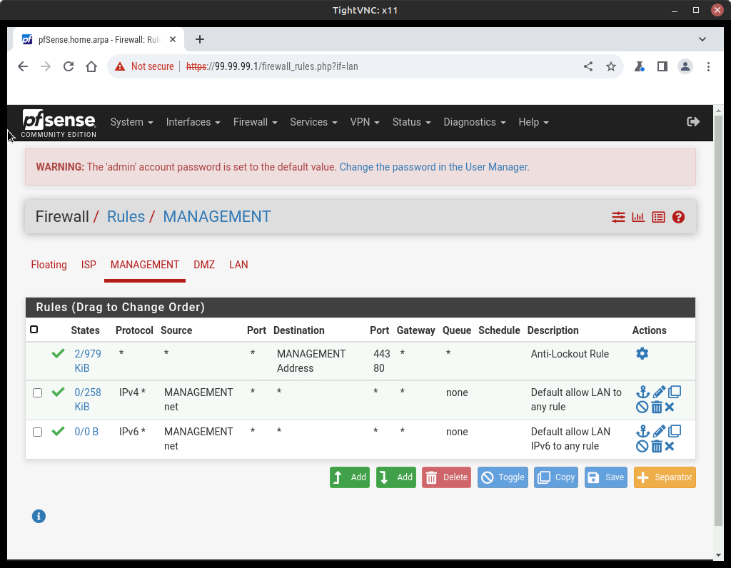
- Click on the Management tab, observe the firewall rules and read the descriptions (Figure 22)
- Anti-Lockout Rule – keeps users from accidentally locking themselves out of the GUI interface
- Default allow LAN to any rule – Does not restrict any access for IPv4 hosts
- Default allow LAN IPv6 to any rule – Does not restrict any access for IPv6 hosts
NOTE: We aren’t using IPv6, so you can delete the Default allow LAN IPV6 to any rule by pressing the trashcan button.
- Click on the DMZ tab to open the rules for the DMZ
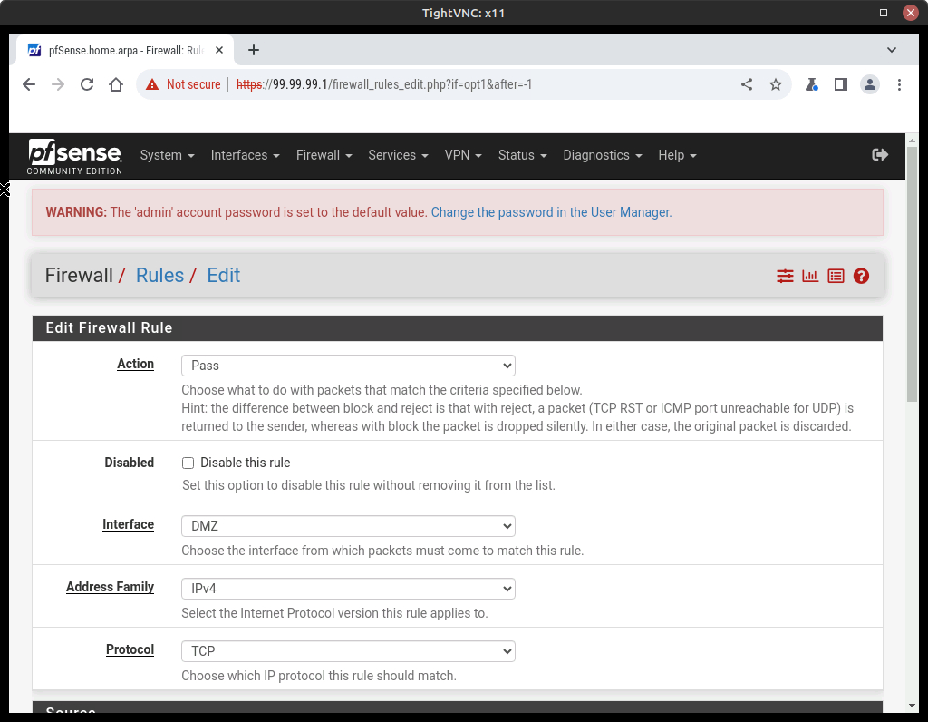
- Click on Add (there are no rules so it doesn’t matter which one) to open the Edit Firewall Rule page (Figure 23)
- Make the following changes using the drop-down menus and textboxes:
Option Value Action Pass Interface DMZ Address Family IPv4 Protocol Any Source DMZ net Destination Any Description Allow DMZ to any rule - Save and apply changes
- Make the following changes using the drop-down menus and textboxes:
- Repeat the above steps for the LAN interface
NOTE: We are going to leave the ISP interface completely blocked for now.
- Test the firewall settings
- From the Management PC, ping the simulated webserver and any of the LAN PCs
NOTE: If you still can’t ping, you have done something wrong and will need to troubleshoot the problem. Did you remember to apply DHCP to all the end devices?
- From the webserver, ping a LAN PC and the Management PC
- From the Management PC, view the webpage hosted on the webserver (http://20.0.0.5:80)
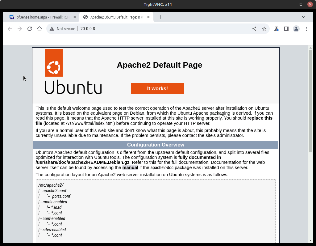
Figure 24 – Default Apache2 website
- From the Management PC, ping the simulated webserver and any of the LAN PCs
Phase V – Separate the DMZ from the LAN
The whole point of a DMZ is to have two separate infrastructures that can’t interact with each other directly, they have to negotiate data transfer through a 3rd party, in this case, pfSense. So we are going to set up traffic blocking between the DMZ and the LAN.
- On the pfSense top menu bar, select Firewall–>Rules–>DMZ
- Edit the existing rule with the following changes:
Option Value Action Block Interface DMZ Address Family IPv4 Protocol Any Source DMZ net Destination LAN net Description Separating the LAN from the DMZ - Click on Save and of course Apply Changes
- Edit the existing rule with the following changes:
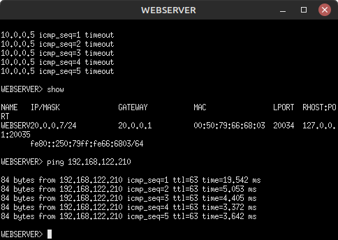
- Now navigate to the web server console and try pinging the LAN PC again. You should get a timeout error
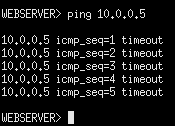
Figure 25 – Webserver pinging PC1 - Right-click on the connection on the webserver-pfSense link and start a Wireshark capture
- Try to ping the LAN PC again. Notice that there is no response from the pfSense server now
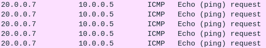
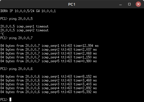
Figure 26 – Failed communication from DMZ to LAN - Navigate to one of the LAN PCs and try to ping the webserver. It should be successful
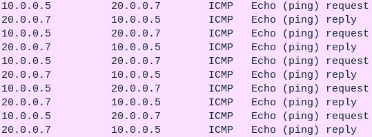
Figure 27 – Successful communication from LAN to DMZ
- Try to ping the LAN PC again. Notice that there is no response from the pfSense server now
Phase VI – Access the Internet
Our web server needs access to the Internet. So we are going to add a rule to allow this to occur. Remember, we are going to use the ISP_Test_PC as our simulated Internet. We are going to allow only the Web_Server to access the Internet through the Firewall. We are going to introduce using Aliases in pfSense for this phase.
- Navigate to the Ubuntu_Desktop and use the browser to get access to the pfSense GUI
- Using the top ribbon menu select Firewall –>Aliases–>Ports
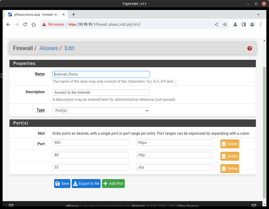
- Select Add and adjust the properties of the Alias as follows (Figure 28)
Option Value Name Internet_Ports Description Access to the Internet Type Port(s) Port(s) Description 443 https 80 http 53 dns - Save and Apply Changes
- Select Add and adjust the properties of the Alias as follows (Figure 28)
- Using the top ribbon menu select Firewall –>Aliases–>IP
- Select Add and adjust the properties of the Alias as follows (Figure 29)
Option Value Name DMZ_Internet_Enabled_Hosts Description Allows machines in DMZ to access the Internet Type Host(s) Host(s) Description 20.0.0.5-20.0.0.100 DMZ network - Save and Apply Changes
- Select Add and adjust the properties of the Alias as follows (Figure 29)
- Using the top ribbon menu select Firewall–>Rules–>DMZ
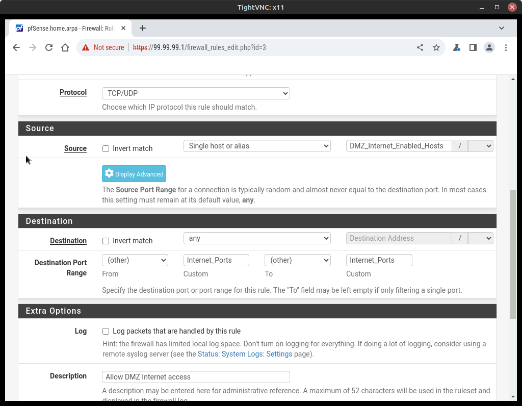
- Select Add and adjust the properties as follows (Figure 30)
Option Value Action Pass Interface DMZ Address Family IPv4 Protocol TCP/UDP Source Single host or alias Source Address DMZ_Internet_Enabled_Hosts Destination Any Description Allow DMZ Internet access Destination Port Range Value From (other) Custom Internet_Ports To (other) Custom Internet_Ports - Save and Apply Changes (Figure 31)
- Select Add and adjust the properties as follows (Figure 30)
Phase VII – ICMP
If you were working ahead, you might have noticed that you can’t ping from the webserver to the ISP_Test_IP. Remember we opened some ports, but Ping is a function of ICMP that doesn’t use ports. We need a separate Alias to allow this.
- Navigate back to Firewall –> Rules–>DMZ
- Add another rule, below the others, with the following settings:
Option Value Action Pass Interface DMZ Address Family IPv4 Protocol ICMP ICMP Subtypes Any Source DMZ net Destination Any Description Allow for Pings - Save and Apply Changes
- Add another rule, below the others, with the following settings:
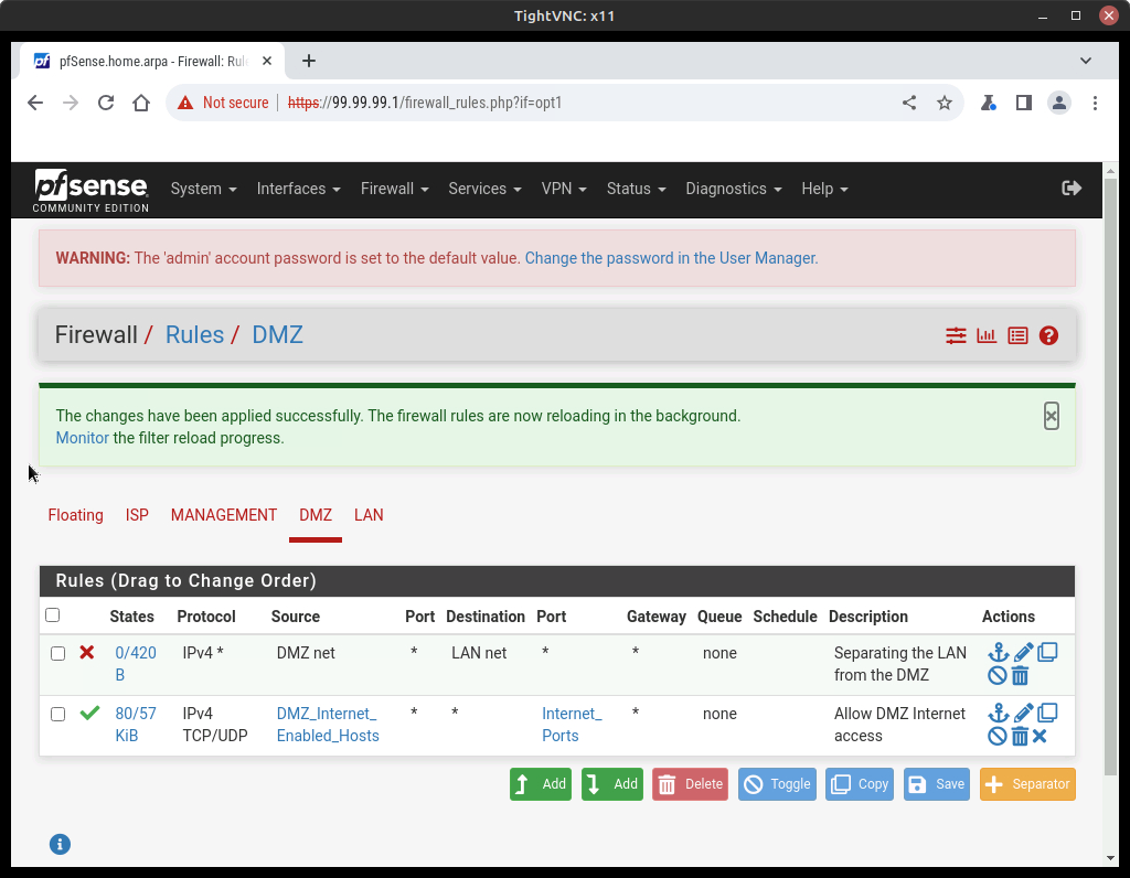
- Verify that you now have three firewalls in place for the DMZ network
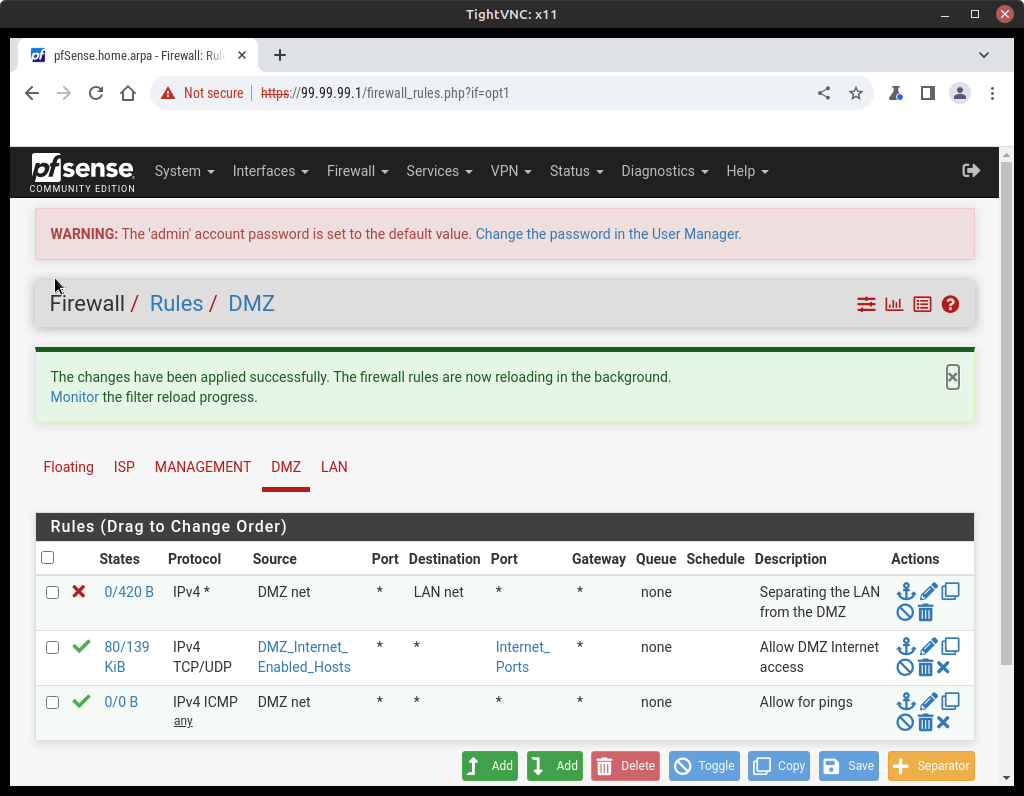
Figure 32 – DMZ firewall rules - Test the communication of the network as it currently stands
- From the Webserver, ping the External PC (it should be successful)
- From PC1, ping the webserver (it should be successful)
- From the External PC, ping the Webserver…
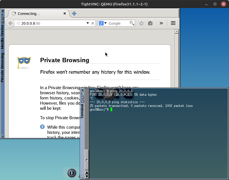
Figure 33 – External PC failed to see webserver Failure! Whether we try to ping or view the default Apache webpage, the external PC is unable to communicate with our DMZ. So how are people going to be able to reach our webserver?
End of Lab
Deliverables
Four screenshots are required to receive credit for completing this exercise:
- Screenshot of the GNS3 workspace with all devices placed and labeled (Phase II)
- Screenshot of the pfSense services dashboard after DHCP has been set up (Phase III)
- Screenshot of the web server successfully pinging a LAN PC and the Management PC (Phase IV)
- Screenshot of the 3 rules for the DMZ (Phase VII)
Homeworks
Assignment 1 – Scan the networks using Kali Linux and nmap
- Import a Kali Linux VM into the GNS3 environment. Use the same network settings as the other devices used in this chapter.
- Attach a cable from the Kali machine to a switch and run nmap looking for active IP addresses and open ports. (type man nmap at the command prompt to read instructions about using nmap)
- Screenshot of ISP switch
- Screenshot of Management Switch
- Screenshot of DMZ switch
- Screenshot of LAN Switch
RECOMMENDED GRADING CRITERIA:
- four screenshots
- ISP has no open ports
- Management has open ports
- DMZ has open ports
- LAN has open ports
List of Figures

