23 Domain Name System Part 1- Authoritative DNS
Jacob Christensen
In previous labs, communication between devices was verified via pinging IP addresses. With the addition of a Domain Name System (DNS) server to our network, these computers can be referenced by a more human-friendly name rather than a hard-to-remember string of numbers.
This lab will demonstrate the configuration and implementation of a basic primary authoritative (local) DNS server for multiple LANs.
Estimated time for completion: 60 minutes
NOTE: There is a large amount of explaining in this lab. Sometimes the dot “.” has different meanings depending on where it is located:
- An octet separator as in 8.8.8.8
- A domain name separator as in red.net
- A Fully Qualified Domain Name (FQDN) indicator as in red.net.
- As a separator between ideas. Idea one. Idea two. Idea three
Experienced cyber operators understand the context of the dot placement and apply its meaning appropriately. Beginners may get confused. Therefore when testers reported confusion we added brackets around the dots to enhance clarity. e.g. in the following examples the domain name separator dots are placed in brackets
e.g. 80[.]30[.]89[.]in-addr[.]arpa. – Ends in a dot denoting a FQDN
e.g. 80[.]30[.]89[.]in-addr[.]arpa – Does not end in a dot denoting it is not a FQDN
learning objectives
- Learn how DNS works on an enterprise network
- Demonstrate how to configure zone files
prerequisites
- One (1) Ubuntu Server VM with Bind9 installed (created in Chapter 7)
- Three (3) Tiny Core Linux VMs (created in Chapter 5)
deliverables
- Screenshot of the GNS3 working environment
- Screenshot of PC1 successfully forward resolving the details of PC2
- Screenshot of PC1 successfully reverse resolving the details of PC3
- Screenshot of PC3 successfully pinging PC2 by name instead of IP
resources
- BIND9 Administrator Reference Manual – https://bind9.readthedocs.io/en/v9.18.16/
- MikroTik RouterOS Documentation – https://help.mikrotik.com/docs/display/ROS/RouterOS
contributors And testers
- Mathew J. Heath Van Horn, PhD, ERAU-Prescott
- Kyle Wheaton, Cybersecurity Student, ERAU-Prescott
Phase I – Building the Network Topology
The following steps are to create a baseline network for completing this chapter. It makes assumptions about learner knowledge from completing previous labs.
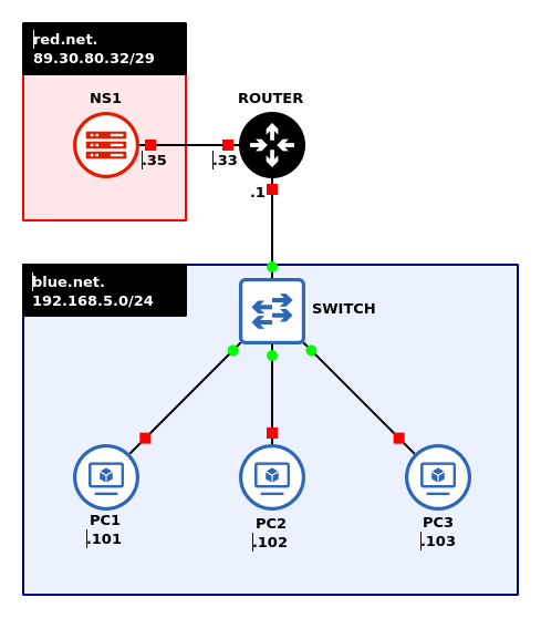
- Preliminary step in VirtualBox
- Create/clone 3 TinyCore virtual machines
NOTE: For easy reference you can name them PC1, BLUE1, etc.
- Create/clone a fresh copy of the Linux Server VM with BIND9 installed
- Create/clone 3 TinyCore virtual machines
- Start GNS3
- Create a new project: LAB_09
- Add the VMs created in Step 1 (Chapter 6)
- Build a subnet – blue.net – with the following specifications:
- Use a randomly generated IPv4 network address space
- Use a network address that minimizes wasted IPs for 250 hosts
- Three client machines – Tiny Core Linux
NOTE: You may use GNS3’s VPCS instead of Tiny Core, but this is not recommended since they do not have the tools dig or nslookup installed. These are tools that are necessary to help troubleshoot DNS. Furthermore, you may need to flush DNS caches to reliably see the Wireshark traffic. It is just easier to use Tiny Core end-user devices from the beginning.
- One Switch – Ethernet switch
- Label each Tiny Core client with the static IP address
NOTE: This example uses the following IPv4 addresses:
– Network: 192.168.5.0/24
– Gateway: 192.168.5.1
– PC1: 192.168.5.101
– PC2: 192.168.5.102
– PC3: 192.168.5.103
- Build a second subnet – red.net – with the following specifications:
- Use a randomly generated IPv4 network address space
- Use a network address that minimizes wasted IPs for 5 hosts
- One DNS server – Ubuntu Server (NS1) with the static IP set
NOTE: the netplan configuration file will always be a .YAML file, however, the name may change between releases or user modifications. This screenshot is using a Ubuntu 22.04.X LTS .YAML file. Adjust as necessary.
NOTE: This example uses the following IP addresses:
– Network: 89.30.80.32/29
– Gateway: 89.30.80.33
– NS1: 89.30.80.35> vi /etc/netplan/00-installer-config.yaml

Figure 2 – NS1 static IP configuration file
- Add a MikroTik router to the workspace
- Connect both networks to the router
- Configure the router with static IPs on all active interfaces
NOTE: This example uses the following IP addresses:
– ether1 – 89.30.80.33/29
– ether2 – 192.168.5.1/24
- Label and organize your network as necessary. When complete it should look like Figure 1

NOTE: Notice the addition of [.]net in our labels. These will be our local domain names for each subnet.
- Configure the first client PC1
- Navigate to PC1’s console
- Modify the system startup script to execute the sethostname binary on boot
NOTE: vi is the only text editor installed by default in Tiny Core.
> vi /opt/bootsync.sh
- Modify the /usr/bin/sethostname line and replace box with PC1
/usr/bin/sethostname PC1

Figure 3 – Setting static IP for PC1 - Save (write) and exit the editor
- Modify the /usr/bin/sethostname line and replace box with PC1
- Configure the first user with a static IP address (192.168.5.101)
- Modify the local startup script to include our custom interface configuration by typing
> vi /opt/bootlocal.sh
- Add the following items to the startup script
- Kill the DHCP client program
pkill udhcpc
- Set the static IP address, netmask, and broadcast address for the eth0 interface
ifconfig eth0 192.168.5.101 netmask 255.255.255.0 broadcast 192.168.5.255 up
- Add a default gateway pointing to the router’s inward-facing interface
route add default gw 192.168.5.1
- Add the local domain name blue.net to the local DNS configuration file
echo “domain blue.net” > /etc/resolv.conf
- Append the address for the primary nameserver (NS1) to the local DNS configuration file
echo “nameserver 89.30.80.35” >> /etc/resolv.conf
- Use Figure 4 for configuration reference

Figure 4 – Startup script modifications - Save and exit the editor
- Kill the DHCP client program
- Reboot the machine to apply the changes
> sudo reboot
- Verify that the changes went into effect
> ifconfig

Figure 5 – Checking to see if the settings took effect
- Modify the local startup script to include our custom interface configuration by typing
- Repeat Step 1 above for Tiny Core clients (PC2 and PC3)
- Ensure full network connectivity by pinging all the devices from PC1 before continuing to the next section
Phase III – Configuring the Authoritative DNS Server
- Start ns1.red.net and login
- Modify the machine’s hostname to ns1
- Open the terminal and assign a new permanent device name using Systemd’s hostnamectl binary
> sudo hostnamectl hostname ns1
NOTE: You can check the hostname in Linux by typing
> hostname
- Add the new name in the hosts file in the /etc directory to prevent name resolution conflicts
> vi /etc/hosts
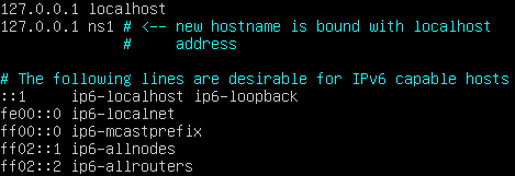
Figure 6 – Modifying the /etc/hosts file to prevent resolution conflict in the future NOTE: If you notice that commands executed with sudo have slowed to a crawl, you may have forgotten to do this step.
- Reboot the machine to apply changes
> reboot
- Open the terminal and assign a new permanent device name using Systemd’s hostnamectl binary
- Assign a static IP address, default gateway, primary DNS server, and local domain name
- Configure the server’s netplan YAML file
> sudo vi /etc/netplan/00-installer-config.yaml
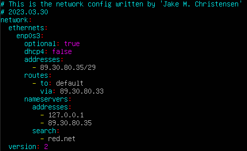
Figure 7 – Modifying the YAML again - Apply the new configuration
> netplan apply
- Verify that the IP address was established
> ip route

Figure 8 – Verifying the IP route was successfully established - Verify that the nameserver information is correctly pointing towards itself (127.0.0.1) and that the current domain is red[.]net
> resolvectl status

Figure 9 – Verifying that the nameserver information is correct
- Configure the server’s netplan YAML file
- Stop and disable Systemd’s time synchronization daemon to avoid unnecessary DNS traffic
> systemctl stop systemd-timesyncd.service
> systemctl disable systemd-timesyncd.service
- Open the DNS daemon configuration file using any text editor you prefer
> vi /etc/bind/named.conf.options
- At the start of the file, before the options directive, add the following access control list (ACL)
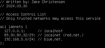
Figure 10 – The addition of ACLs to the configuration file NOTE: ACLs are important for preventing unauthorized access to machines or services. In this case, all subnets can use this server for DNS queries, however, clear specification is always good practice.
- In the same file, add the following commands in the options directive
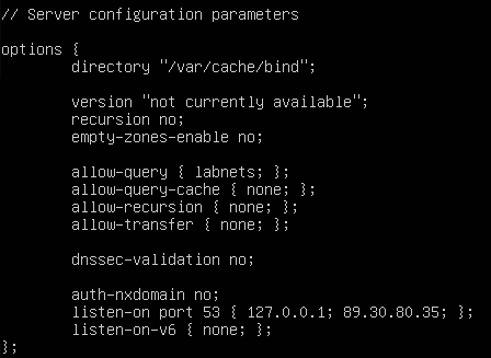
Figure 11 – Adding options to the same configuration file NOTE: There may already be configuration options here by default. Feel free to delete or modify them as you see fit.
Command Description version Specifies the version number of the BIND9 server to return in response to a version query. Official BIND9 documentation suggests that this be set to “not currently available” to avoid detailed service enumeration from threat actors. recursion Defines whether recursion ( and caching of queries as a result of recursion) are allowed. empty-zones-enable Enables or disables all empty zones. Setting to “no”, allows the mapping of private IP addresses to hostnames (such as 192.168.x.x) if they are used on the network. By default, this is set to “yes”. allow-query Defines which networks, if any, are allowed to query its service. allow-query-cache Defines which networks, if any, are allowed to query cached domains. allow-recursion Defines which networks, if any, are allowed to access recursion services on the server. dnssec-validation Defines whether DNS validation is enabled. listen-on Defines which ports and addresses to listen on and respond to DNS queries. - Save (write) and exit the editor
- Verify that the file was configured correctly
> named-checkconf /etc/bind/named.conf.options
NOTE: No response indicates that no errors were detected. Otherwise, read the error carefully and fix syntax as necessary.
- At the start of the file, before the options directive, add the following access control list (ACL)
- Modify the service zone configuration file to specify the domains our server will have authority over
> vi /etc/bind/named.conf.local
NOTE: Two types of zones must be created for each domain: forward lookup zones and reverse lookup zones. The former translates domain names to IP addresses while the latter does… the reverse. AKA, IP addresses to domain names.
- Add the following forward lookup zones to the configuration file
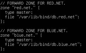
Figure 12 – Add forward lookup zones for red and blue networks NOTE: Notice how the zone declarations end with a dot [.]. This is a fully qualified domain name (FQDN). Make sure to pay special attention when FQDNs are being used going forward. Forgetting to include the period is an easy typo, but it can cause a major headache when debugging later.
Command Description zone FQDN of the domain the server will have authority over. type Declares whether this machine is the primary (master) or secondary (slave) server for this zone. file Declares the location of the database file for this zone. - In the same file, add the following reverse lookup zones
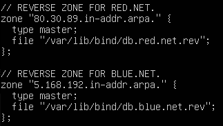
Figure 13 – Add reverse lookup zones for the red and blue networks by IP addresses NOTE: Notice how the first tree octets in the zone declaration are in LITTLE ENDIAN order. This is known as a reverse ARPA address. Make sure to double-check everything for typos. In reverse ARPA addresses, you only need to declare the octets that will be static. For instance, the correct syntax for the network 176[.]55[.]0[.]0/20 would be 55[.]176[.]in-addr[.]arpa[.] since host addresses can range from 176[.]55[.]0[.]1 to 172[.]55[.]15[.]254. Because this CIDR mask allows for such a large range of host addresses, the third octet can vary in value, so its reverse ARPA address must be adjusted in response.
Little Endian vs Big Endian
Endian can be confusing to people who have never programmed computer memory space. It means which end of a number goes first. Remember back to second grade, numbers have a one’s place, ten’s place, hundred’s place, etc…
Little Endian – Write the number starting at the little end (the one’s place).
Big Endian – Write the number starting at the big number (the highest number place).
Computer memory and programs use First In First Out (FIFO) and First In Last Out (FILO) mechanisms for various reasons. Reasons that are beyond the scope of these labs. It is enough to know that FIFO and FILO exist, making Endian notation necessary.
SIMILE TIME: Endian is like a crowded elevator with two doors; front and back. The following people enter the elevator from the front doors.
– Miracle (Enters first, stands at the back of the elevator)
– Maribel
– Scott
– Rory
– Halle
– Lucian (Enters last, stands at the front of the elevator)If they travel to the 5th floor, the front doors open and Lucian will exit the elevator first and Miracle will exit the elevator last (FILO).
However, if they travel to the 6th floor, the rear doors open and Miracle will exit the elevator first and Lucian will exit the elevator last (FIFO).
Now, let’s say the people must exit the elevator in a particular order, so the usher needs to know which order to have the folks enter the elevator. The usher knows that the 5th and 6th floors open differently, so when the ordered list is prepared, the usher will use Little Endian notation for the 5th floor or Big Endian notation for the 6th floor.
Back to computers: Using an IP in Endian notation. We can say our PC has an IP address of 192.168.1.5 so that translates to:
– Big Endian Notation 192.168.1.5
– Little Endian Notation 5.1.168.192 - Save and exit the configuration file editor
- Verify the file was configured correctly using the following command
> named-checkconf /etc/bind/named.conf.local
NOTE: Again, no response indicates that no errors were detected. Otherwise, fix file syntax as necessary. Pay attention to FQDNs.
- Add the following forward lookup zones to the configuration file
Phase IV – Configure Zone Resource Record (RR) Files
Each zone specified in the previous section needs a dedicated database to store domain information. Several have already been provided in the /etc/bind directory. The database files can be identified by the ones starting with “db” (database) and are loaded in the “named.conf.default-domains” configuration file. We can use these as a starting point for making our own RR files.
- Create a new forward data file for the Red subnet
- View the contents of the bind directory to see what database files are available
> ls -l /etc/bind
- Copy any db file of your choice
> cp /etc/bind/db.empty /var/lib/bind/db.red.net
NOTE: Ensure the renamed file matches the one specified in Phase III when we declared our zones. We used:
db.red.net
db.blue.net - Configure the newly created file to act as the Red subnet’s forward lookup data file
> vi /var/lib/bind/db.red.net
- Rename the comment at the start of the file to reflect its new purpose
NOTE: In these files, the semicolon denotes a note instead of a command.
; BIND9 forward data file for red.net.
- Below $TTL, add the following directive
$ORIGIN red.net.
NOTE: This will append the base domain name to any domain that is not terminated with a dot [.]. For example, the string ns1 will be interpreted as ns1[.]red[.]net[.]. Conversely, the string ns1[.] will be read as only ns1[.]. This is why paying attention to FQDNs is important, for strings such as ns1[.]red[.]net (without the terminating dot) will be read as ns1[.]red[.]net[.]red[.]net[.] by the server.
- In the Start of Authority (SOA) declaration, overwrite the local host information with the master DNS server domain
@ IN SOA ns1.red.net. hostmaster.red.net. (
- Increment the Serial value by one
2 ; Serial
NOTE: Whenever this file is edited in the future, the serial number should be incremented again.
- Leave the Refresh/Retry/Expire/Negative Cache TTL values as their defaults for now
- Replace the current name server (NS) entry with all available domains (in this case, there is only one server)
@ IN NS ns1.red.net.
- Since we only have one device in the Red zone, we need to map it with its static layer 3 internet (IN) address (A)
ns1 IN A 89.30.80.35
- Save the file and exit the editor
- Use this image for configuration reference
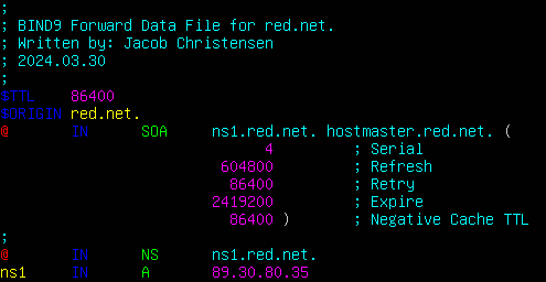
Figure 14 – Configuring the forward data file for red.net.
- Rename the comment at the start of the file to reflect its new purpose
- Verify that the file was configured correctly and correct any errors as necessary
> named-checkzone red.net. /var/lib/bind/db.red.net
- View the contents of the bind directory to see what database files are available
- Create a new reverse data file for the Red subnet
- Copy any db file of your choice
> cd /var/lib/bind
> cp db.red.net db.red.net.rev
NOTE: We recommend the new file name ends with [.]rev to quickly identify it as a reverse lookup database file.
- Open the new reverse data file with any text editor
> vi /var/lib/bind/db.red.net.rev
- Rename the comment at the start of the file to reflect its new purpose
; BIND9 reverse data file for red.net.
- Below $TTL add the following directive
$ORIGIN 80.30.89.in-addr.arpa.
NOTE: Once again, the octets are in LITTLE ENDIAN order. This dictates the base internet address (in-addr) that will be appended to any incomplete IP addresses later. For example, the IP address 35 will be interpreted as 35[.]80[.]30[.]89[.]in-addr[.]arpa[.] otherwise known as 89[.]30[.]80[.]35.
- In the Start of Authority (SOA) declaration, specify the master DNS server domain
@ IN SOA ns1.red.net. hostmaster.red.net. (
- Increment the Serial value by one
2 ; Serial
- Leave the Refresh/Retry/Expire/Negative Cache TTL values as their default for now
- Replace the current NS entry with the master DNS server domain
@ IN NS ns1.red.net.
- Map the server’s currently assigned IP addresses (last octet) with its associated FQDN
35 IN PTR ns1.red.net.
NOTE: If you are mapping IP addresses with a shorted reverse ARPA address, then do not forget to include both host octets. For example, the address 176[.]55[.]2[.]15/20 would be represented as 55[.]176[.]in-addr[.]arpa[.] in the $ORIGIN directive and mapped as 15[.]2 IN PTR pc.example[.]com[.].
- Save the file and exit the editor
- Use this image for configuration reference
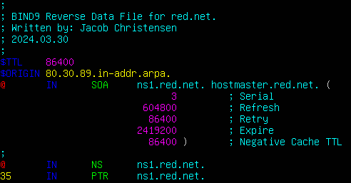
Figure 15 – Reverse data file for red.net.
- Rename the comment at the start of the file to reflect its new purpose
- Verify that the file was configured correctly
> named-checkzone 80.30.89.in-addr.arpa. /var/lib/bind/db.red.net.rev
- Copy any db file of your choice
- Repeat the above process and make another set of forward and reverse lookup files for blue.net
NOTE: Don’t get confused. The name server is in the red network. That is why the SOA and NS will remain unchanged.
- /var/lib/bind/db.blue.net
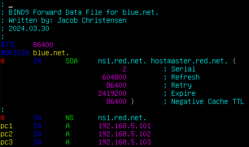
Figure 16 – Forward data file for blue.net. > named-checkzone blue.net. /var/lib/bind/db.blue.net
- /var/lib/bind/db.blue.net.rev
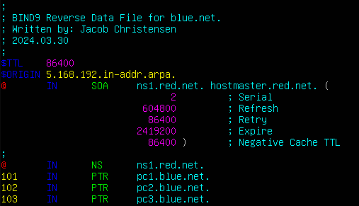
Figure 17 – Reverse data file for blue.net. > named-checkzone 5.168.192.in-addr.arpa. /var/lib/bind/db.blue.net.rev
- /var/lib/bind/db.blue.net
- Modify the permissions for the zone files
- Change the owner and group from root to the bind user
> chown bind:bind /var/lib/bind/db.*
- Change the file permissions to have read and write access for both the owner and group
> chmod 664 /var/lib/bind/db.*
- Change the owner and group from root to the bind user
- Start the DNS daemon and ensure that all zones loaded properly
> systemctl daemon-reload
> systemctl enable named.service
> systemctl restart named.service
> systemctl status named.service
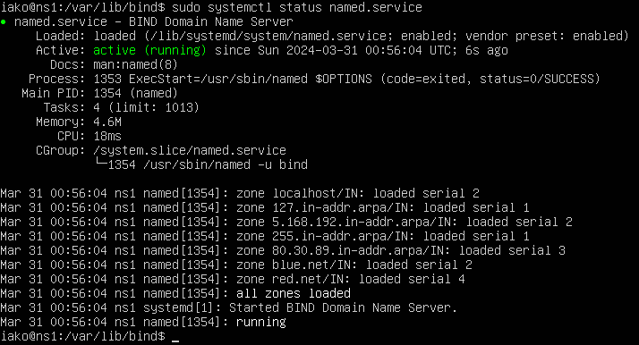
Figure 18 – BIND is running without errors
Phase V – Wireshark Captures
Now that our network is set up, let’s watch live packet captures to see what DNS queries look like in action.
- Start a Wireshark capture between NS1 and the router
- Open the terminal of PC1
- Test the service by performing a DNS query on PC2
> nslookup pc2

Figure 19 – Successful nslookup query NOTE: Since they are both in the same network, the blue[.]net domain does not need to be specified. To communicate with a device outside the LAN, the full domain name of the recipient is needed.
- In Wireshark, you should see a Standard query IPv4 (A) packet sent to NS1 and a Standard query response packet containing the resolution

Figure 20 – successful nslookup query as viewed on Wireshark NOTE: You may see additional IPv6 queries (AAAA) in addition to IPv4. You can safely ignore these since we have not configured IPv6 on our DNS server.
- You can also perform a reverse DNS lookup with the nslookup binary to discover the hostname of a machine given its IP address
> nslookup 192.168.5.102

Figure 21 – Successful reverse nslookup - Again, you should see a Standard query hostname (PTR) packet sent to the NS1 and a Standard query response packet containing the mapped IPv4 address

Figure 22 – reverse nslookup on Wireshark
- Test the service by performing a DNS query on PC2
- From PC1, ping the DNS server
> ping ns1.red.net
- If the full domain name is not given, the local name will be appended instead and the name will not be resolved
> ping ns1

Figure 23 – nslookup fails NOTE: Notice how the domain ns1[.]blue[.]net was queried instead of ns1[.]red[.]net.
- If the full domain name is not given, the local name will be appended instead and the name will not be resolved
- Congratulations! You have successfully configured an authoritative DNS server with static IP addresses in your network
End of Lab
Deliverables
- Screenshot of the GNS3 Working environment
- Screenshot of PC1 successfully forward resolving the details of PC2
- Screenshot of PC1 successfully reverse resolving the details of PC3
- Screenshot of PC3 successfully pinging PC2 by name instead of IP
Homeworks
Assignment 1 – Add a Green network to the router:
- Use a random IP address space
- Use two end devices
- Plan for the addition of 313 machines
- Modify the DNS server to include the new subnet
Assignment 2 – Add a Purple network to the router:
- Use a random IP address space
- Use two end devices
- Minimize wasted address space for 245 machines
- Modify the DNS server to include the new subnet zones
RECOMMENDED GRADING CRITERIA
- Wireshark screenshots of successful purple.net forward and reverse domain resolution
- Wireshark screenshots of successful green.net forward and reverse domain resolution
- Screenshot of GNS3 workspace that is neatly organized and labeled
Figures for Printed Document
There are no clickable figures in the digital edition which need to be placed here for the print edition.

