23 Static Networking Part 1
Kyle Wheaton and Jacob Christensen
Up to this point, we have only used one router in our working environments. However, you will rarely work on a network with only a single LAN because the whole point of an enterprise network is to connect multiple LANs into a unified cohesive network.
In this lab, we will create and connect three LANs via routers. We introduce you to static routing solutions so you can become familiar with routing procedures. Static routing is impractical mainly because it is very manpower intensive to maintain and prone to human error.
Estimated time for completion: 70 minutes
Learning objectives
- Successfully create two functional LANs:
- Red (DHCP + 2 PCs)
- Blue (DHCP + 2 PCs)
- Configure two routers to use static routing so all devices can communicate
Prerequisites
Deliverables
- Screenshot of GNS3 workspace with labels
- Screenshot of Wireshark IMCP packets showing a Red device successfully pinging a Blue device
Resources
- MikroTik RouterOS Documentation – IP Routing – https://help.mikrotik.com/docs/display/ROS/IP+Routing
- Internet Systems Consortium – Kea Administrator Reference Manual – https://kea.readthedocs.io/en/latest/
Contributors and Testers
- Dante Rocca, Cybersecurity Student, ERAU-Prescott
- Kyle Wheaton, Cybersecurity Student, ERAU-Prescott
Overview
You are now going to combine your subnet, DHCP, and router configuration skills to create two networks, each with their own gateway routers. Your final product should look similar to the following.

Phase I -Build the Network Topology
The following steps are to create the baseline for completing the lab. It makes assumptions about learner knowledge from completing previous labs. Going forward, we will be using Ubuntu Servers for all network servicing needs. For those who have limited computational resources, consider using TinyCore as an alternative.
- Start GNS3
- Create a new project: LAB_07
- Build the Red subnet with the following specifications:
- IP address space – 115.20.20.0/24
- Two client machines – VPCS
- One switch – Ethernet switch
- One DHCP server – Ubuntu Server VM (isc-dhcp-server)
- One router – MikroTik CHR
- Connect the server and PCs to their associated switch
- Connect the switch to the router’s ether1 interface
- IP address space – 115.20.20.0/24
- Configure the MikroTik router to act as Red’s gateway
NOTE: Refer to Chapter 18, Phase II, Step 4 for more information.
- Set a new hostname to reflect its new purpose
> system identity set name=RED-ROUTER
- Set ether1 with the IP address 115.20.20.250 for the Red network
> ip address add address=115.20.20.250/24 interface=ether1
- Verify that it was taken
> ip address print
MikroTik Configuration Preface
By default, MikroTik routers will have a DHCP client enabled on interface ether1, which will automatically request an IP address once the network’s DHCP server is online. To avoid unnecessary packet traffic (and troubleshooting headaches), disable this client as part of the router’s setup routine. You can identify interfaces with DHCP clients enabled via the “dynamic” (D) flag that appears next to its identification number.

Figure 2 – Dynamically assigned IP address List all DHCP clients currently enabled on the device.
> ip dhcp-client print

Figure 3 – Default MikroTik DHCP listener Remove the DHCP client. When editing or deleting entries in RouterOS, you “select” a target row based on its number (#) in the first column. In this instance, we are removing entry zero.
> ip dhcp-client remove 0

Figure 4 – Remove default DHCP listener Verify that all IP addresses are now static. Note that this method can also be used to remove or edit accidental interface IP assignements. Instead of ip dhcp-client remove #, the syntax would be ip address remove #, where # represents the row you wish to select.

Figure 5 – Print currently assigned IP addresses
- Set a new hostname to reflect its new purpose
- Configure Ubuntu Server to act as Red’s DHCP server
NOTE: Refer to Chapter 20, Phase II, Steps 2-7 for more information.
- Assign its Ethernet card with the static IP address of 115.20.20.254/24 and a default gateway of 115.20.20.250 (ether1 on the Red router)
> sudo vi /etc/netplan/50-cloud-init.yaml

Figure 6 – The network configuration file - Apply the configuration
> sudo netplan apply
- Configure the DHCP daemon with a host range of .10 to .150 in addition to a gateway address to ether1 on the Red MikroTik router
> sudo vi /etc/kea/kea-dhcp4.conf

Figure 7 – Red Lan DHCP config NOTE: Notice the addition of option routers in this configuration file. This will automatically assign a gateway address to DHCP clients.
- Assign its Ethernet card with the static IP address of 115.20.20.254/24 and a default gateway of 115.20.20.250 (ether1 on the Red router)
- Have each VPCS request a new IP address
> ip dhcp
- Ensure that all devices within the LAN can ping each other
- Repeat steps 2 through 6 to build the Blue subnet
- Blue will have the IP address space of 68.110.45.0/24
- The Blue router’s IP on ether1 is 68.110.45.250
- The Blue DHCP server’s static IP is 68.110.45.254
- The Blue DHCP daemon will have the same specifications as Red

Figure 8 – Blue Lan DHCP config
- Label and organize your network as necessary

Figure 9 – GNS3 working environment
Phase II – Join Networks to their Host LANs
Routers are very similar to post offices. If a letter comes into the post office and the destination address is within the neighborhood, the post office will hand the letter to another carrier. This is of limited value, but the router earns its paycheck when the letter needs to go to another neighborhood. The postmaster will find the most efficient route to get the letter to the right neighborhood.
To get used to this idea, we are going to configure our routers just to speak to their local “homes” and the post office in the next neighborhood. We are not worried about efficiencies at this point, let’s just get the postmasters talking. This kind of configuration is called static routing because nothing changes.
- On the Red router, set ether2 with the static IP address 10.10.10.1/29 for the Backbone network
> ip address add address=10.10.10.1/29 interface=ether2
NOTE: A backbone is network IP space that is only used by routers to speak to each other. In this example, we are using 10.10.10.0/29 which has a maximum of six host addresses. This while only two devices (router interfaces) are currently connected on this network, this leaves room for four more potential devices.
- On the Blue router, set ether2 with the static backbone IP address 10.10.10.2/29
> ip address add address=10.10.10.2/29 interface=ether2
- Connect Red router’s ether2 interface with Blue router’s ether2 interface

Figure 10 – Connected Gateways
Phase III – View Capabilities of our Current State
Congratulations! You have built two LANs and connected them together through routers. Or have you? Remember, if a networked device has no idea where to send a data packet, it will discard it. This part of the lab lets you see this concept in action.
- Start two Wireshark data captures
- Red-Switch to Red-Router
- Red-Router to Blue-Router
- Open PC1 and ping Red-Router
> ping 115.20.20.250
- Observe the ICMP packets on the Red-switch to Red-Router Wireshark window

Figure 11 – ICMP ping packets
- Observe the ICMP packets on the Red-switch to Red-Router Wireshark window
- Now from PC1, ping Blue-Router
> ping 10.10.10.2
- Observe the ICMP packets on the Red-Router to Blue-Router Wireshark Window

Figure 12 – Failed ICMP ping packets What happened? What is the problem? Maybe we configured the routers wrong.
- Observe the ICMP packets on the Red-Router to Blue-Router Wireshark Window
- Open the Red-Router console and ping the Blue-Router by typing
> ping 10.10.10.2
- Observe the ICMP packets on the Red-Router to Blue-Router Wireshark Window

Figure 13 – ICMP ping packets between routers That worked, so what is the problem?
- Observe the ICMP packets on the Red-Router to Blue-Router Wireshark Window
- Open the PC1 console and ping the Blue Network DHCP server by typing ping 68.110.45.250
> ping 68.110.45.254
- Observe the ICMP packets on both Wireshark data packet captures

Figure 14 – ICMP destination unreachable error What do you see? What is happening?
- Observe the ICMP packets on both Wireshark data packet captures
Phase IV – Configure the Routers
Even though the routers know what networks are connected to them, they have no knowledge of the networks that are not connected to them. Let’s look at our current network.

Ok, we are only concerned with one path, so let’s simplify our diagram to the essentials.

The switches are unmanaged, so we don’t even need them for this explanation. So we’ll take those out, change our routers to use color symbols, add the IP addresses, and label the simplified links, which takes our diagram down to the essentials.

Remember what a ping packet (ICMP) does: It sends a request to a target interface and asks that interface to send it back to the originator.
When the Red PC pings the Red Router we can see the packets on Link A for both request and response.
Try it – Open a Wireshark capture for Link A. Then from the PC 1 console type ping 115.20.20.250
The Red Router knows that network 115.20.20.0 is connected to ether1 and sends the response.
Now when Red Router pings Blue Router we can see the packets on Link B for both request and response.
Try it – Open a Wireshark capture for Link B. Then from the Red Router console type ping 10.10.10.2
The Blue Router knows that network 10.10.10.0 is on ether2 and sends the response.
However, when Red PC pings the Blue Router, the Red Router forwards the packets to Blue Router, but when Blue Router tries to send the response packets back to Red PC, it has no idea what interface to use to send packets to network 115.20.20.0, so it never sends the responses.
Finally, when Red PC pings the Blue PC, it has no idea where to send the request packets, so it just throws up its arms and tells us, “Nope. I’m out.”
We are going to fix this problem.
- Stop the Wireshark captures (this saves our host machine’s resources)
- Configure a static routing table on the Red subnet’s router
- Open the Red-Router console
- Add a new static route to our Red-Router
> ip route add dst-address=68.110.45.0/24 gateway=10.10.10.2
Command Purpose ip route add Add a new IPv4 route dst-address=68.110.45.0/24 Any packet trying to go to the 68.110.45.0 network gateway=10.10.10.2 Forward the packet to this destination interface
- Configure a static routing table on the Blue subnet’s routers
- Add a new static route to our Blue Router by navigating to the Blue Router Console and typing
> ip route add dst-address=115.20.20.0/24 gateway=10.10.10.1
- Add a new static route to our Blue Router by navigating to the Blue Router Console and typing
- Now navigate to PC1 and try to ping the Blue router or any Blue end device

Figure 18 – ICMP ping working Congratulations! You successfully implemented a basic network using static routing!
Phase V – Add a Green Subnet
You now have all the tools to build a LAN, add it to a network, and configure routers so that the LANs can send packets back and forth. Time to try it on your own.
- Create a Green LAN similar to our Red and Blue LANs
- Use a randomly generated IPv4 network address space
- Use a network address that minimizes wasted IPs for 35 hosts
- Ensure that it has two VPCS’s, one DHCP server, and one Ethernet switch
- Connect the Green subnet to the Red router
- Configure the Red Router so the Green and Red LANs can ping each other
- Configure the Blue Router so the Green and Blue LANs can ping each other
- Label and organize your network as necessary
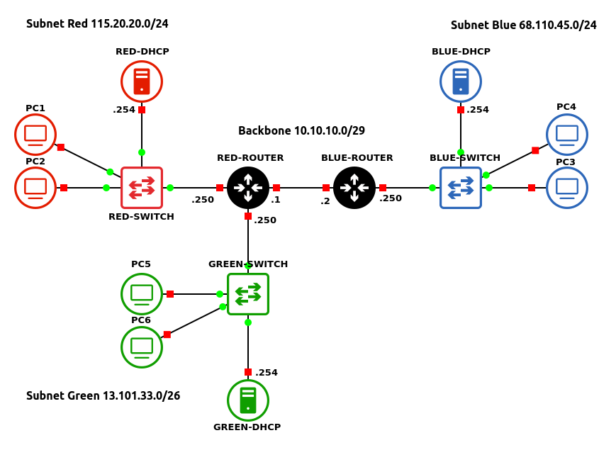
Figure 19 – Green LAN added to the network example
End of Lab
Deliverables
4 screenshots are required to receive credit for this lab
- Screenshot of GNS3 workspace with everything labeled
- Screenshot of Wireshark IMCP packets
- A Green device successfully pinging a Blue device
- A Green device successfully pinging a Red device
- A Red device successfully pinging a Blue device
Homeworks
Assignment 1 – Add two more LANs to the Blue Router
- Add a gray network to the Blue Router
- Add a Purple network to the Blue Router
- RECOMMENDED GRADING CRITERIA
- Screenshot of GNS3 Workspace with all devices labeled
- Green network is using randomly generated IP address
- Grey network is using randomly generated IP address
- Wireshark Packet Captures
- Grey end device successfully pinging a Red end device
- Grey end device successfully pinging a Green end device
- Green end device successfully pinging a Red end device
- Green end device successfully pinging a Blue end device
- Screenshot of GNS3 Workspace with all devices labeled
Assignment 2 – Add a new router and LAN
- Add a third router and LAN to the GNS3 Workspace called Network Gray
- The Grey LAN should use a randomly generated IP space
- You will need to configure router interfaces for all routers using the backbone IP space
- You will need to configure static routes for each router
- RECOMMENDED GRADING CRITERIA
- Screenshot of GNS3 Workspace
- Gray LAN is using randomly generated IP address space
- Wireshark PacketCaptures
- Gray LAN device successfully pinging Red LAN device
- Gray LAN device successfully pinging Blue LAN device
- Screenshot of GNS3 Workspace