18 Introduction to Routers
Jacob Christensen
Simply stated, where switches and hubs connect end devices (desktops, laptops, smartphones, etc.), routers connect switches and hubs to each other. Routers are the devices that enable the internet to function. This is an elementary introduction to using routers for first-time learners. This lab will build two LANs and connect them using a MikroTik router.
Estimated time for completion: 20 minutes
Learning Objectives
- Demonstrate successful router configuration using two or more local area networks
- Increase experience in utilizing virtual environments in learning enterprise networks
- Analyze Wireshark results to identify Ethernet packets and frames
prerequisites
Deliverables
Four screenshots are required:
- PC1 console successfully pinging PC4
- Wireshark results (ICMP packets) of PC2 successfully pinging PC3
- Neatly labeled and organized GNS3 Workspace
- Configuration settings of the MikroTik router console (interface print, IP address print)
Resources
Contributors and testers
- Mathew J. Heath Van Horn
NOTE: Students should be familiar enough with GNS3 by now to understand the commands. This lab starts reducing the number of screenshots since these things were documented in previous chapters.
Overview
You will use your LAN knowledge to build two networks. Then, you will use a router to connect these networks together. Your final product should look similar to this.

Phase I – Configure the Red and Blue Networks
Most networks have a specific purpose. They can be centered around a function (marketing) or geography (front building). In our examples, we generally use colors to abstract the learners from the specific functions. This way, learners won’t be locked into a certain configuration for an “Accounting” department.
- Start GNS3
- Create a new project: Name it anything you like, but we named ours LAB_03
- Build the Red LAN with the network address 100.10.10.0 and netmask 255.255.255.0
NOTE: /24 is CIDR notation for the subnet mask of 255.255.255.0, which is itself a decimal representation of the binary octets 11111111.11111111.11111111.00000000 used to name network interfaces (the /24 represents the number of 1’s used). These PCs accept CIDR and subnet mask notation, but not all end devices do. So get familiar with using both ways to assign IP addresses.
- Use two VPCS devices for PC1 and PC2
- Add an Ethernet switch
- Connect the PCs to the switch
- Start the PCs and assign them appropriate host addresses
- Configure PC1 to have a host address of 100.10.10.1
> ip 100.10.10.1/24
> save
- Configure PC2 to have a host address of 100.10.10.2
> ip 100.10.10.2/24
> save
- Configure PC1 to have a host address of 100.10.10.1
- Organize your network
- Label the machines with both their IP address and hostname for clarity
- Add a textbox with the subnet network address using either CIDR notation or traditional subnet masks
- To help visually differentiate the subnets, change the device symbols or use the Draw a rectangle button to encapsulate the LAN with its associated color
NOTE: You may have to send the square to the background by right-clicking on it and then selecting the Lower one-layer option.
- Test network connectivity by opening the console for PC1 and pinging PC2
> ping 100.10.10.2
- Repeat to build Blue LAN with the network space of 200.20.20.0/24
- Configure PC3 with the host address 200.20.20.10
- Configure PC4 with the host address 200.20.20.20
- Verify that your network looks similar to the following

Figure 2 – Basic GNS3 network
NOTE: In the figures, you can see different methods of labeling and visual organization:
- The Red LAN posts the network ID and just the host part is next to the device
- The Blue LAN uses the complete network ID next to each device
As discussed earlier, hubs and switches connect end devices to create LANs (this is an overly simplistic explanation, but it suffices in this instance). Now, we are going to use a router to connect the individual LANs to form an enterprise network.
- Import the MikroTik appliance from the GNS3 marketplace
- Connect the Red and Blue LANs to a router
- Drag a MikroTik router to the workplace
- Connect a cable from the Red switch to the ether1 router interface
- Connect a cable from the Blue switch to the ether2 router interface
NOTE: Unlike the switches, taking note of which router ports are in use is VERY IMPORTANT!
- Start the router and open its console
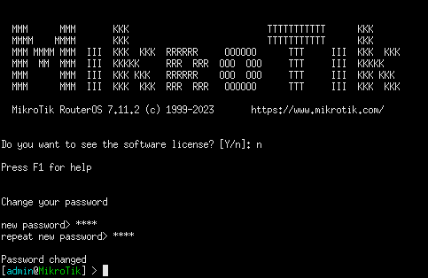
Figure 3 – MikroTik router login screen - Login: admin
- Password: (nothing just hit Enter)
- Set a new password (ex. Security1)
NOTE: You can change the hostname of the router for clarity. This will be useful when we build more complicated and interconnected networks later.
> system identity set name=new_name

Figure 4 – Set new router hostname MikroTik Router Troubleshooting
If the router is stuck in an infinite boot loop (called throttling), ensure that KVM acceleration is DISABLED in the GNS3 VM configuration file.

Figure 5 – GNS3 VM main menu 
Figure 6 – GNS3 VM configuration
- Configure ether1 with a Red IP address
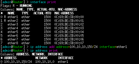
Figure 7 – setting an IP address - View the list of Ethernet ports on the router
> interface print
- Assign the IP address of 100.10.10.150 to ether1
> ip address add address=100.10.10.150/24 interface=ether1
- Ensure the IP address has been taken
> ip address print
- From the MikroTik router, try pinging one of the Red PCs from its console

Figure 8 – VPCS connectivity test NOTE: Routers will ping indefinitely, whereas end devices usually only ping 4 to 5 times. Routers’ continuous pinging aids troubleshooting efforts. To stop the pinging, ensure the MikroTik console is active and press Ctrl+C.
- Troubleshoot as necessary until there’s connectivity between the Red PCs and ether1 on the router
- View the list of Ethernet ports on the router
- Configure ether2 with the Blue IP address of 200.20.20.250 by following step 4
- Verify that your network looks similar to the following

Figure 9 – Finalized GNS3 network - From PC4, try to ping PC1
NOTE: You will get a No gateway found error. This is expected. At the time we built our LANs, we didn’t have a router. Now we need to configure our PCs to include the gateway address for their respective networks. The gateway address is the address the endpoint (ex PC1) needs to send its packets when the destination is outside of the LAN.

Figure 10 – No gateway found - Use the VPCS IP command to assign each PC a gateway address
- The gateway address for the Red network is 100.10.10.150 (router port ether1)
- Configure PC1’s gateway addresses
> ip 100.10.10.1/24 100.10.10.150
- Configure PC2’s gateway address
> ip 100.10.10.2/24 100.10.10.150
- Repeat these steps to add the appropriate gateway address (200.20.20.250) to PC3 and PC4
Phase III – Testing your network
Testing – Testing – Testing. It never ends.
- Open Wireshark packet capture between PC1 and the Red Switch
- Use PC1’s console to ping PC4
> ping 200.20.20.20

Figure 11 – PC1 pinging PC4 - Watch Wireshark for the ARP and ICMP packets

Figure 12 – Wireshark packet capture - Verify that you can do this between any two points in the network
End of Lab
Deliverables
Four screenshots are required to receive credit for this exercise:
- PC1 console successfully pinging PC4
- Wireshark results (ICMP packets) of PC2 successfully pinging PC3
- Neatly labeled and organized GNS3 Workspace
- Configuration settings of the MikroTik router console (interface print, ip address print)
Homeworks
Assignment 1 – Add a Green LAN to the network.
| DEVICE | IP ADDRESS | NETWORK MASK | GATEWAY ADDRESS |
| PC5 | 177.50.0.1 | 255.255.255.0 | 177.50.0.250 |
| PC6 | 177.50.0.2 | 255.255.255.0 | 177.50.0.250 |
| Router Interface | 177.50.0.250 | 255.255.255.0 | none-this is the gateway! |
Assignment 2 – Add the Green and Purple LAN to the network.
| DEVICE | IP ADDRESS | NETWORK MASK | GATEWAY ADDRESS |
| PC7 | 10.10.0.1 | 255.255.0.0 | 10.10.255.250 |
| PC8 | 10.10.0.2 | 255.255.0.0 | 10.10.255.250 |
| PC9 | 10.10.0.3 | 255.255.0.0 | 10.10.255.250 |
| PC10 | 10.10.100.1 | 255.255.0.0 | 10.10.255.250 |
| Router Interface | 10.10.255.250 | 255.255.0.0 | none-this is the gateway! |
Recommended binary grading criteria:
- Screenshot of the GNS3 Working environment where:
- All connections are made according to instructions
- All connections are labeled with the correct IP Address
- Interface labels are turned on
- Everything is organized neatly
- Screenshot of Wireshark packet captures taken from the PC5-Switch link
- PC5 from the Green subnet can successfully ping PC2 in the Red subnet