A-5: Forces and Moments
Pressure and Shear Stress Distributions for Resultant Aerodynamic Forces and Moments
Shigeo Hayashibara
Pressure and Shear Stress (force) Distributions
Aerodynamic Forces and Moments of an Airfoil
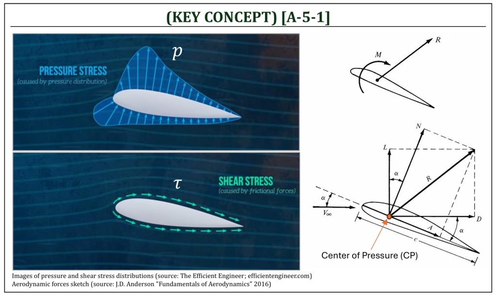
Let us understand the fundamental concept of aerodynamic forces and moments. First, let us take a close look at a cross section of an aircraft wing (called, an airfoil) in a flow field. There will be two different types of distributed loading on the surface of an aircraft wing: (i) pressure stress (p) distribution (normal force per unit surface area of an aircraft wing) and (ii) shear stress (τ) distribution (shear force per unit surface area of an aircraft wing).
Aerodynamic Forces and Moments of an Airfoil
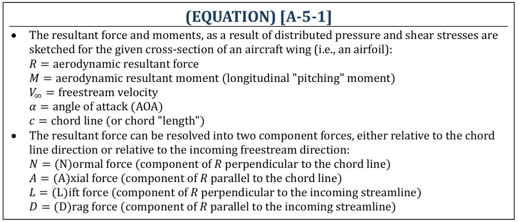
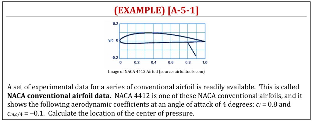
The surface distributed loading (pressure and shear stress) can be integrated into the resultant force (R) and moment (M) for a given cross section of a wing (please recall, from statics, this is the equivalent force & couple-moment pair on a body). Note that this resultant force (R) and moment (M) pair can be defined at any location, but typically we choose along a given chord line of an airfoil (i.e., the direction of the chord). The chord line is a straight line drawn from the front end (leading edge, or L.E.) to the aft end (trailing edge, or T.E.) of a given airfoil. The exact location along the chord line can be expressed in % of the chord line length (called, chord length or c) measured from the leading edge. A very commonly used reference location is 25% chord (called, the quarter chord) location. This is (as you discover later) often called the location of the aerodynamic center.
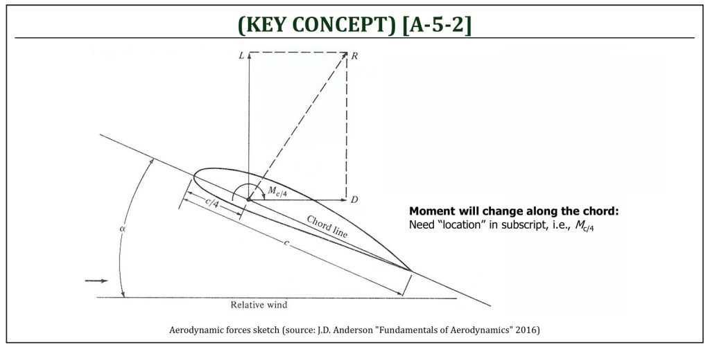
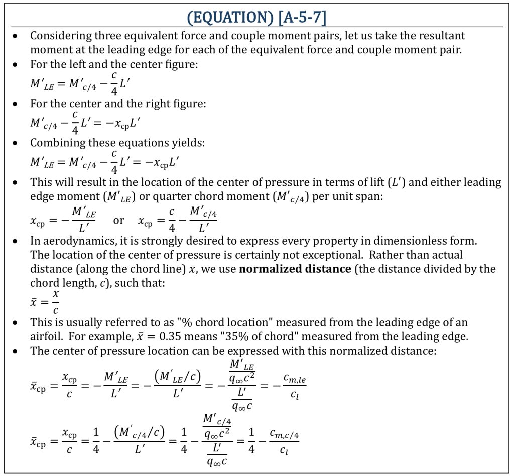
Note that, as you move (i.e., slide along the chord line) the location of this resultant force (R) and moment (M) pair, the moment will certainly change. There will be a location, along the chord line, that the moment (M) becomes zero. This is (as you will discover later) called, the center of pressure (CP) location.
Lift, Drag, and Pitching Moment
Lift, Drag, and Pitching Moment (and Coefficients)
Let us understand the fundamental concept of how to quantify aerodynamic forces and moments. In aerodynamic analysis, we almost always need to deal with model (i.e., smaller than actual size) based calculations. Therefore, we should convert forces and moment properties (lift, drag, and moment) into dimensionless properties that are independent of the size. Let us define dimensionless aerodynamic coefficients of lift, drag, and moment.
Lift, Drag, and Pitching Moment Coefficients
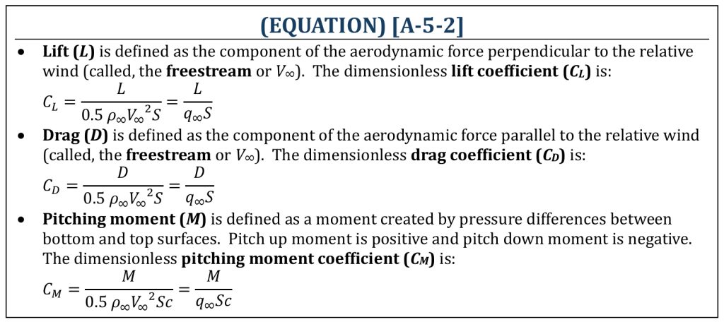
Note that the moment depends on the location, about where we choose to take moments at: therefore, the subscript must always be associated with the moment. For example: MLE (leading edge), Mc/4 (quarter chord), and MTE (trailing edge), where: MLE, ≠ Mc/4 ≠ MTE (i.e., you must always specify the actual location, along the chord line, that you took the moment, in a subscript).
2-D (Airfoil) and 3-D (Finite Wing) Geometry Definitions
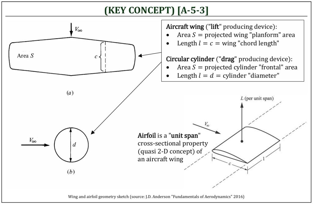
Note that an area (S) and a length (l) needs to be introduced for each coefficient. These are called, the characteristic area and length that are essentially arbitrary choices for refence. A projected area (how much area “can you see” from a given direction) is selected for characteristic area for aerodynamics. For an aircraft, a view from “above” (projected planform area) is commonly chosen. For a “drag producing” device (i.e., parachute), a view from “front” (projected frontal area) is commonly chosen.
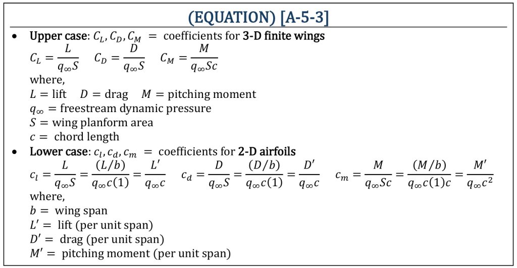
Aerodynamic coefficients are dimensionless properties. Therefore, size independent and can be defined in either 3-D (a finite “wing“) or 2-D (a cross section of a wing, called an “airfoil“). It is a common practice that upper case: CL, CD, CM = coefficients for 3-D finite wings and lower case: cl, cd, cm = coefficients for 2-D airfoils. Aerodynamic coefficients for a given cross section of an aircraft wing (an “airfoil“) can be defined, and this is usually the starting point of an aircraft design analysis. An airfoil can be defined as a “per unit span” property of an infinite wing. Therefore, properties of an airfoil are all defined all “per unit span” basis.
2-D (Airfoil) and 3-D (Finite Wing) Coefficients
Aerodynamic Forces and Moments per Unit Span (1): Fundamentals
Pressure and Shear Stress Distributions and Aerodynamic Forces and Moments
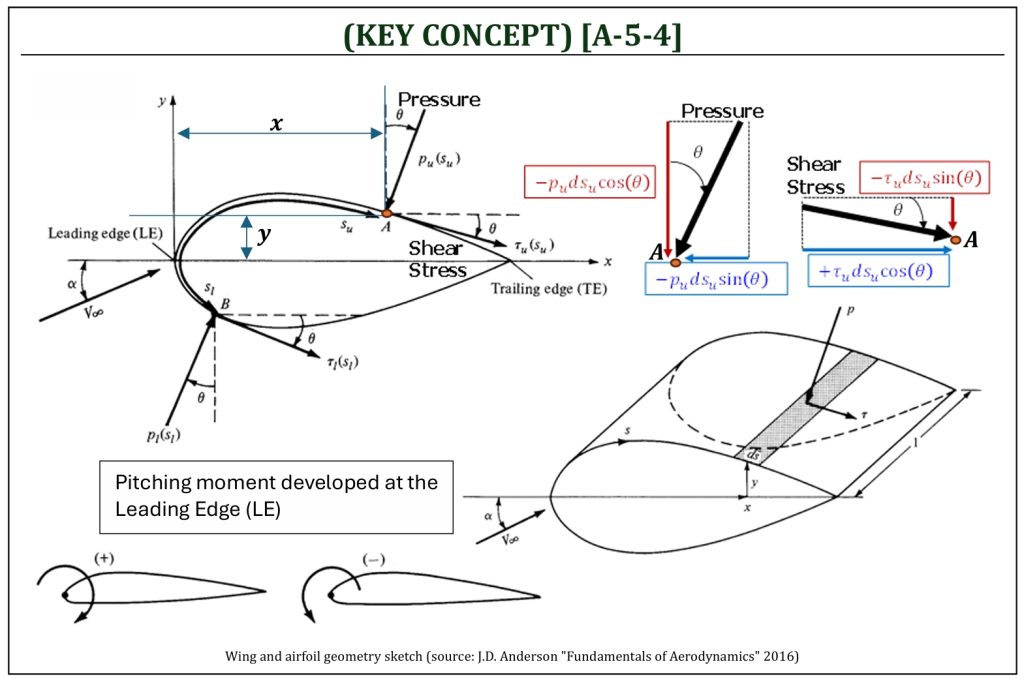
Let us consider a 2-D body: a cross section of a wing (airfoil). The normal and axial forces (per unit span) will be developed due to pressure (p) and shear stress (τ) distributions over the upper and lower surfaces of this airfoil. Let us examine a small element ds (along the curved streamline coordinate system: s) on upper (u) and lower (l) surfaces of this airfoil. If we consider the coordinate origin (the leading edge: LE), the resultant moment (around the leading edge) can also be calculated by the force developed at ds with the corresponding offset distance (x and y).
Differential Forces and Moments (per Unit Span)
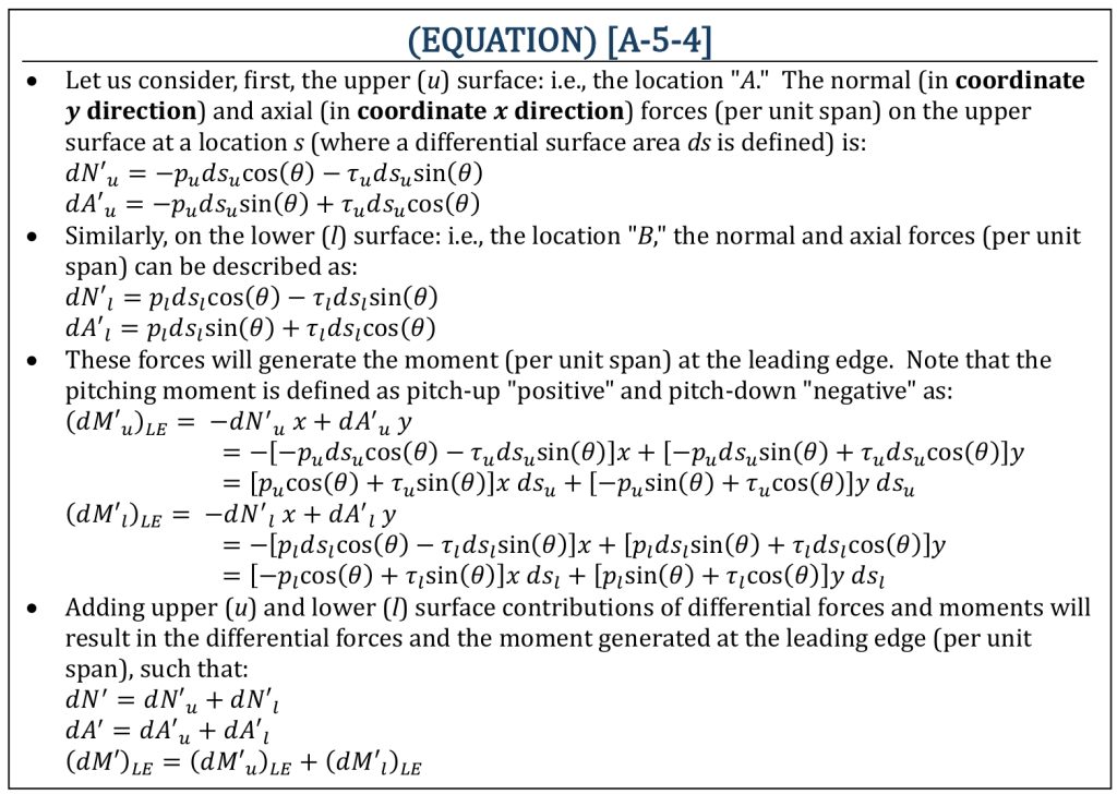
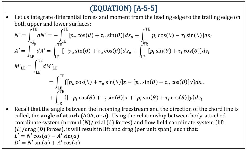
In order to calculate forces (normal and axial), as well as pitching moment developed at the leading edge (per unit span), one needs to integrate differential forces and moment from the leading edge to the trailing edge on both upper and lower surfaces.
Aerodynamic Forces and Moments (per Unit Span)
Aerodynamic Forces and Moments per Unit Span (2): Coefficients
Cartesian Coordinate System and Streamline (Curved) Coordinate System
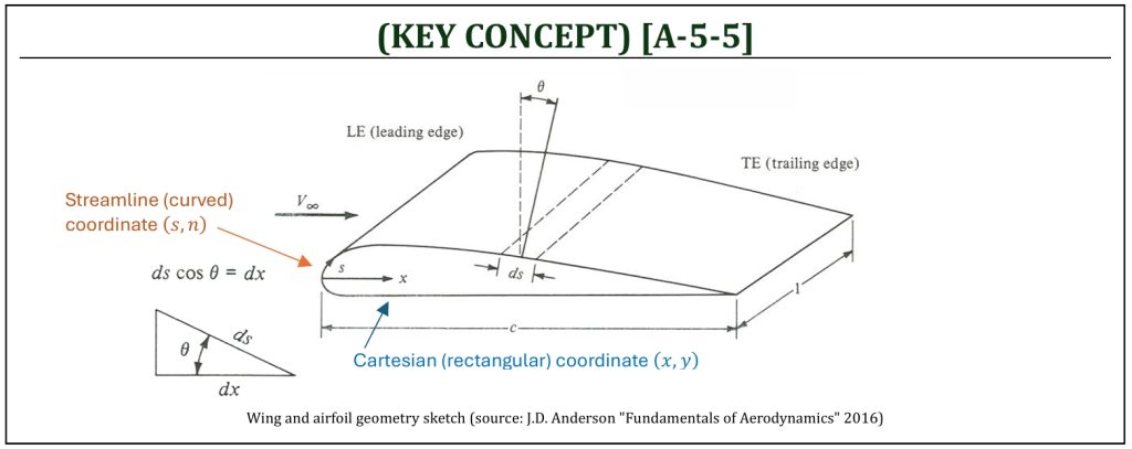
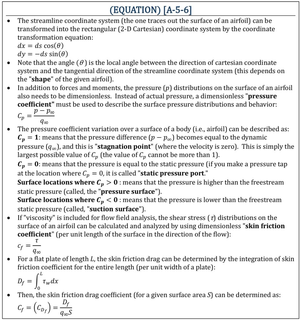
Often, as we focus on the flow phenomena on the “surface” of an airfoil, it is convenient to employ a “curved” coordinate system (s) called the streamline coordinate system. This is a coordinate system that one of the streamlines (usually a curved line) is simply chosen as a reference coordinate system. The direction “tangent” (s) and direction “normal” (n) to the path are perpendicular to each other. The particular streamline that follows through the surface shape is called the stagnation streamline in the potential (ideal) flow analysis that will be covered later in detail.
Coordinate Transformations and Some Additional Coefficients
The Center of Pressure of an airfoil
The Center of Pressure (CP)
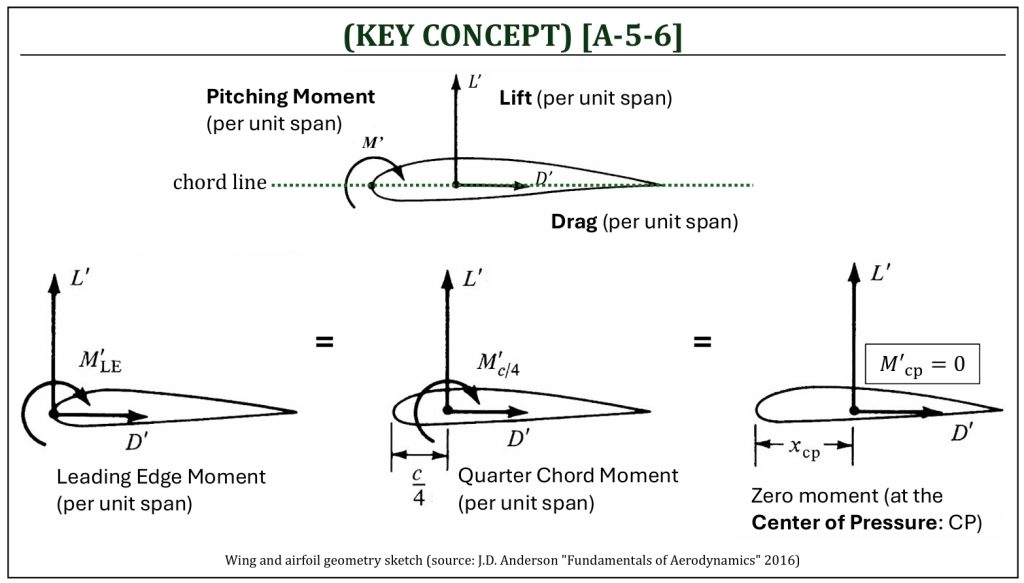
The center of pressure (CP) is the location (along the chord line), where the resultant of distributed loads (i.e., pressure and shear stress distributions) effectively acts on the body. At the center of pressure, the pitching moment is equal to zero. The location of the center of pressure can be found by considering the free-body diagram of equivalent resultant force and couple moment pairs. As the resultant force (resolved into lift and drag forces) along any location of the chord line is placed, the associated pitching moment values varies, depending on the location along the chord line. The center of pressure is the location (along the chord line) where the pitching moment becomes zero.
The Center of Pressure (CP)
The Center of Pressure (CP)
The Aerodynamic Center of an airfoil
The Aerodynamic Center (AC)
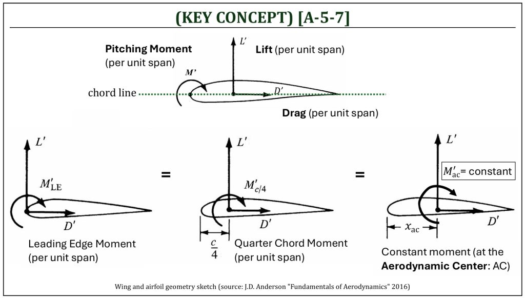
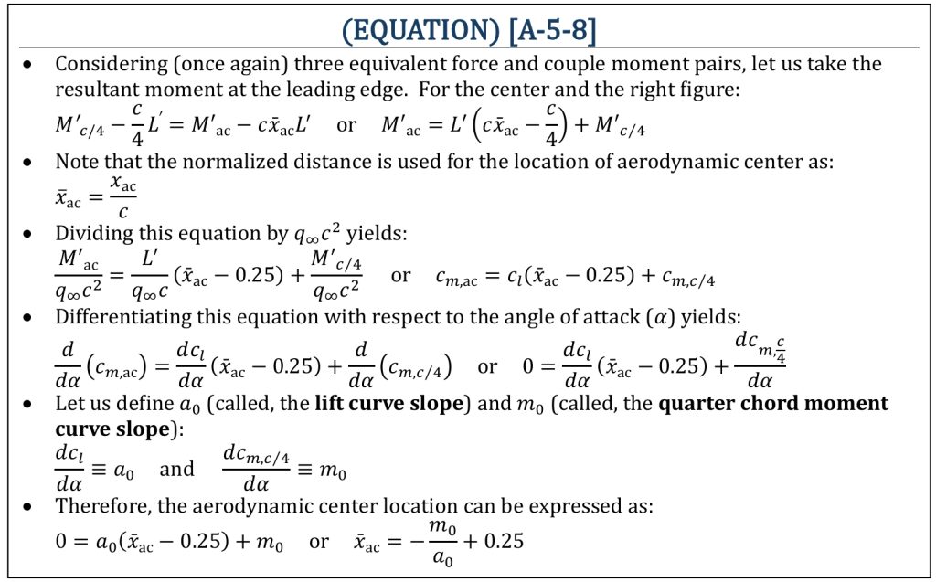
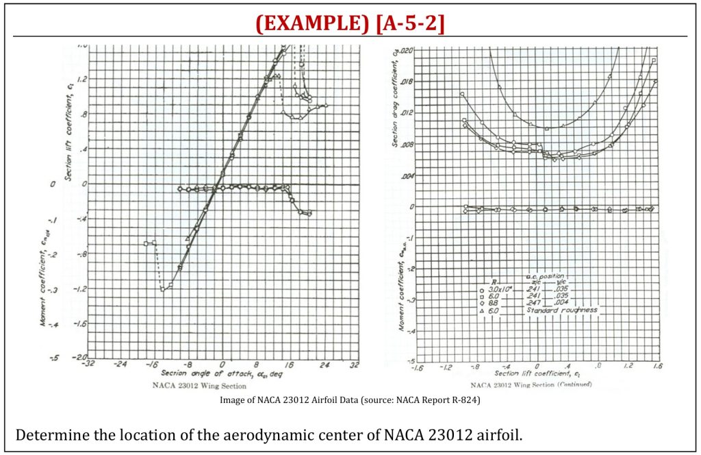
The center of pressure (CP) is, in fact, not quite useful as a reference location of where the aerodynamic forces (i.e., lift and/or drag) acts through. As angles of attack (α) of an airfoil change, the corresponding locations of the center of pressure (xcp) will also change. The aerodynamic center (AC) is the location (along the chord line), where the aerodynamically generated pitching moment becomes independent of the angle of attack (α). Using the location of the aerodynamic center (xac) as the reference location of aerodynamic analysis makes it very convenient.
The Aerodynamic Center (AC)
The Aerodynamic Center (AC)
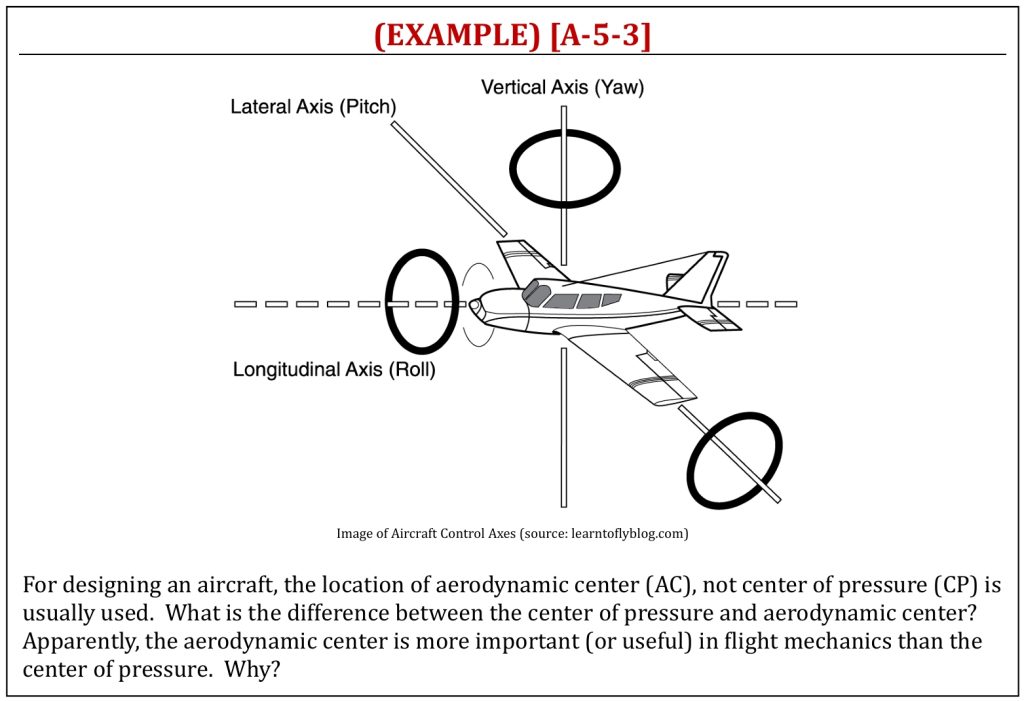
The Aerodynamic Center (AC) and Aircraft Control Basics
References
- NASA (www.nasa.gov)
- Experimental Aircraft Association (https://www.eaa.org/eaa/learn-to-fly)
- The Efficient Engineer (https://efficientengineer.com)
- AirfoilTools (https://airfoiltools.com)
- Fundamentals of Aerodynamics by J.D. Anderson, 5th ED, McGraw Hill, 2016
- Aerodynamics for Engineers by J. J. Bertin & M. L. Smith, 3rd ED, Cambridge University Press, 1997
- Aerodynamics for Engineering Students by E. L. Houghton & P. W. Carpenter, 4th ED, Edward Arnold, London, 1993
Media Attributions
If a citation and/or attribution to a media (images and/or videos) is not given, then it is originally created for this book by the author, and the media can be assumed to be under CC BY-NC 4.0 (Creative Commons Attribution-NonCommercial 4.0 International) license. Public domain materials have been included in these attributions whenever possible. Every reasonable effort has been made to ensure that the attributions are comprehensive, accurate, and up-to-date. The Copyright Disclaimer under Section 107 of the Copyright Act of 1976 states that allowance is made for purposes such as teaching, scholarship, and research. Fair use is a use permitted by copyright statute. For any request for corrections and/or updates, please contact the author.
