D-2: Aerodynamics of Wings (2)
Aerodynamics of 3-D Finite Wings (2 of 2)
Shigeo Hayashibara
compressibility effects
Wing Sweep for High-Speed Flight
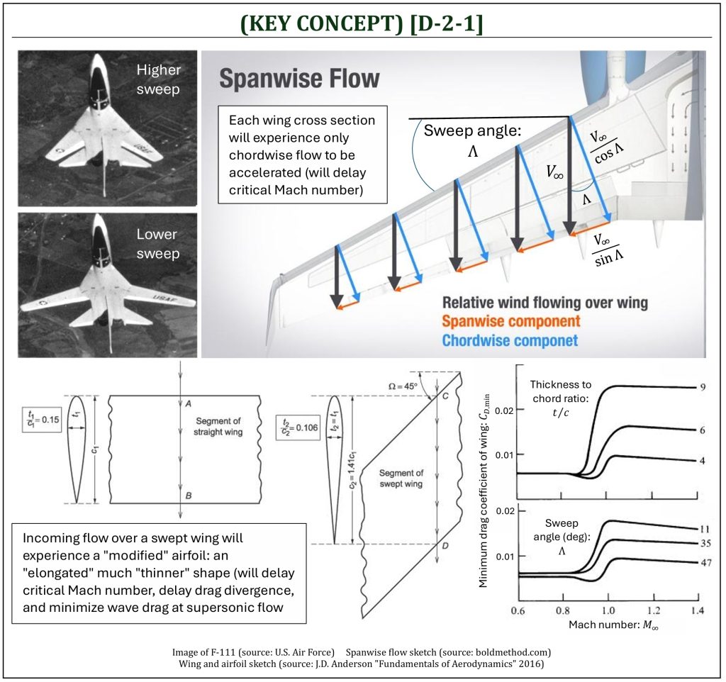
Recalling from C-2, the critical Mach number (Mcr) is the highest freestream Mach number without any partially developed supersonic flow regions on the surface of a 2-D airfoil. Typically, a drag divergence (MDD) will start to happen (significant increase of drag). This will make significant negative impacts for a 3-D finite wing, especially for a high-speed aircraft. Recalling also from C-2, choosing appropriate airfoil shape, such as NASA-SC variant airfoils, would delay Mcr and MDD. As a 3-D finite wing is designed for high-speed flight applications, “sweeping” of the wing would further delay Mcr and MDD during high-subsonic and supersonic flights. The followings are the summary of pros and cons of wing sweeping.
- By sweeping the wing, each airfoil section of the wing “experiences” unparallel freestream velocity. As a result, each airfoil section (in the direction of wingspan) needs to deal only with a velocity component parallel to its chord direction (it is called “chordwise” flow, which is less than freestream itself). However, as a byproduct of the wing sweep, a velocity component normal (perpendicular) to its chord direction (it is called “spanwise” flow) would exist. This spanwise flow component may induce some negative effects, including flow separation.
- By sweeping the wing, the freestream “experiences” an increased geometric chord length (in the direction of incoming freestream). Hence, the effective thickness ratio thickness-to-chord ratio: t/c) is reduced.
- Recalling from EQUATION [D-1-4], by sweeping the wing, the lift curve slope is effectively reduced. This is, in fact, not so good (especially at low-speed flights). Also, in order to produce the same amount of lift, a wing area must be (obviously) larger than the wing without sweeping.
Note that a commonly employed term “drag count” is a unit of “drag change” (ΔCD) defined by aerospace engineers. A drag count is 1/10,000 (0.0001) change of CD. For example, if a drag is increased by 0.01, it is called, “100 count” of drag increase. A drag count is used as a crude measurement for the change in drag coefficient associated with a configuration change, as it is not a direct measure of drag with any reference area. Now, as we carefully observe the effects of both “thickness” (thickness-to-chord ratio: t/c) and “sweep” (average wing sweep angle: Λ) for a 3-D finite wing at high-speed flights, one can conclude as follows:
(1) By decreasing the thickness ratio from 9% => 6% => 4%:
-
t/c 9% => 6%: approximately 100 drag count decrease (ΔCD = –0.01).
-
t/c 6% => 4%: approximately further 70 drag count decrease (ΔCD = –0.007).
(2) By increasing wing sweep from 11° => 35° => 47°:
-
11° => 35°: approximately 30 drag count decrease (ΔCD = –0.003).
-
35° => 47°: approximately further 50 drag count decrease (ΔCD = –0.005).
High-Lift (lift augmentation) devices
High-Lift Devices and Stall Speed
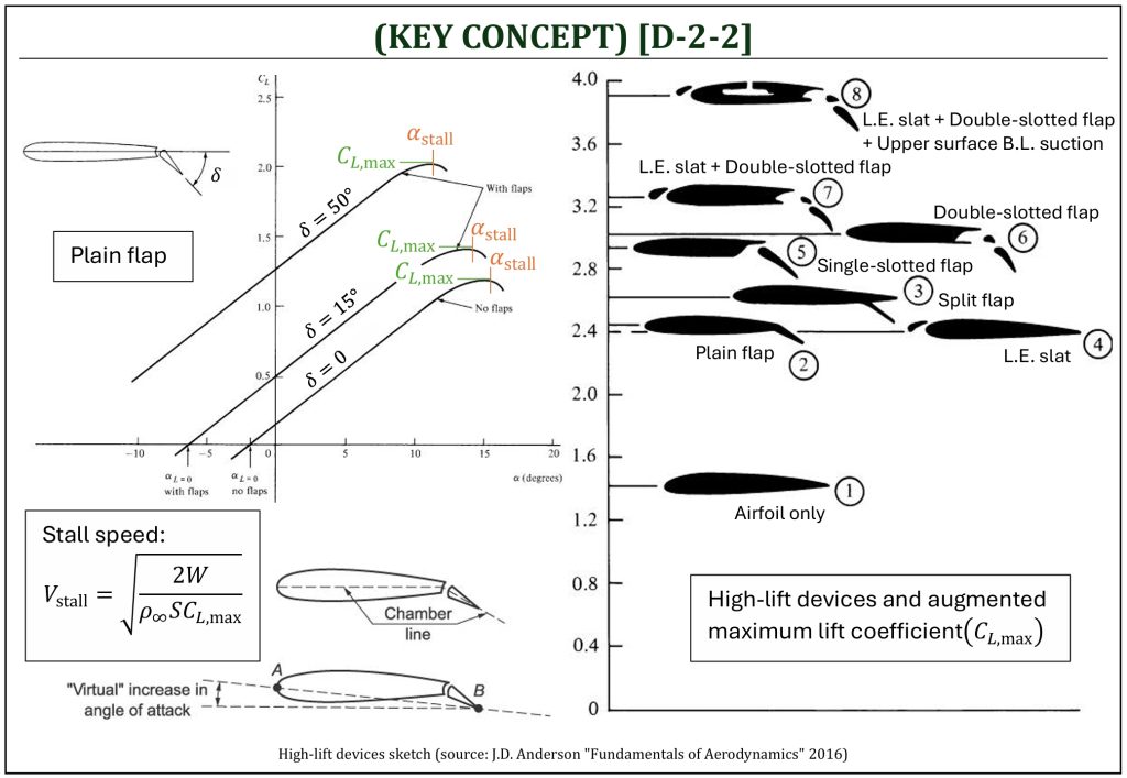
The aircraft flight performance, especially during takeoff and landing (TO-L), depends on the wing’s capability of producing a lift at low speed flight conditions. What would be the lowest possible flight condition? The minimum sustainable airspeed for an aircraft without stall is called the “stall speed.” This is an important parameter, as this is a driving factor of TO-L performance (also it is important for a safety operation of an aircraft).
Stall Speed
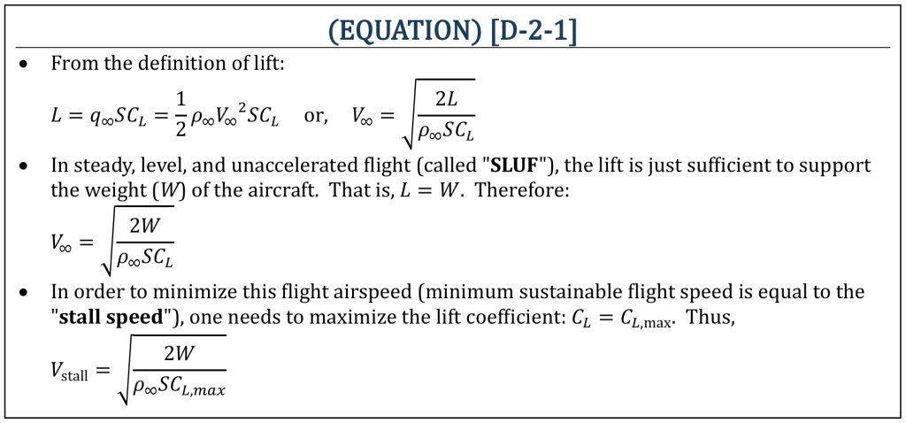
In order to make the stall speed lower, obviously, one needs to (at least temporarily) increase the maximum lift coefficient for TO-L operations. This is the basic concept of “high-lift devices” (flaps, slats, and other devices). Typically, the maximum lift coefficient (cl,max) of an airfoil is in the range of 1.4–1.5. However, this is only applicable for 2-D airfoil. 3-D finite wing’s maximum lift coefficient (CL,max) is (because of the lift curve slope reduction: a => a0) slightly less than that, depending on how much lift curve slope reduction is applied. Usually, an aircraft needs to generate maximum lift coefficient (CL,max) in the range of 1.8–2.4 for effective TO-L operations. It is required to deploy high-lift devices to achieve this. There are many varieties of high-lift devices, but the following two basic types of devices:
-
Trailing edge devices are called “flaps.”
-
Leading edge devices are called “slats.”
By deploying the flaps/slats, one can (temporarily only during TO-L operations) increase the maximum lift coefficient. It is, however, important to understand the trade-off of temporary increase of lift at TO-L operations. It will cause (i) substantial increase of drag and (ii) decrease of stall angle of attack (αstall). Some commonly used variations of high-lift devices are listed here:
(1) Airfoil only (plain wing): maximum lift coefficient (CL,max) in the range of 1.4–1.5.
(2) Plain flap: maximum lift coefficient (CL,max) in the range of 2.4–2.5.
(3) Split flap: maximum lift coefficient (CL,max) in the range of 2.5–2.6.
(4) Leading edge (L.E.) slat: about the same effects of a plain flap.
(5) Single-slotted flap: maximum lift coefficient (CL,max) in the range of 2.9–3.0.
(6) Double-slotted flap, typically with increase of trailing edge (T.E.) extension (enlarged wing area, called “Fowler flap“): maximum lift coefficient (CL,max) in the range of 3.0–3.1.
(7) Double-slotted flap (Fowler) + Leading edge slat: maximum lift coefficient (CL,max) in the range of 3.3–3.4.
(8) Double-slotted flap (Fowler) + Leading edge slat + Top surface boundary layer suction (active B.L. control): maximum lift coefficient (CL,max) in the range of 3.8–3.9.
Pros and Cons of Wing Sweep and Flaps
Wingtip devices
Wingtip Devices
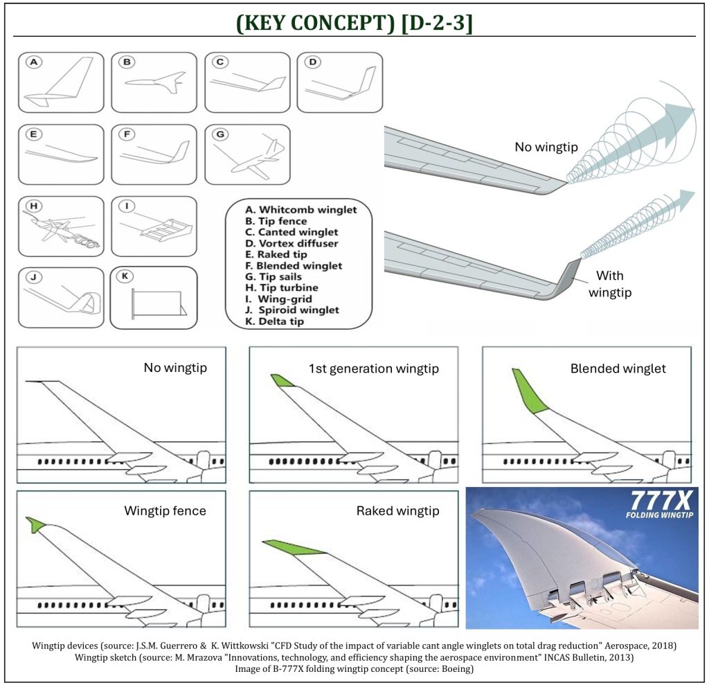
Wingtip devices are intended to improve the efficiency of a 3-D finite wing by controlling the magnitude and behavior of wingtip vortices (then, resulting the reduction of the induced drag (although there are so much variety in shapes of wingtip devices, their intended effect is always to reduce the induced drag of a wing). Wingtip devices reduce induced drag by increasing the height of the lifting system, without much increasing the wingspan itself. Note that increasing the wingspan would reduce the induced drag, but may increase the skin friction (parasite) drag. Also, adding a wingtip device will require higher structural integrity (consequently an increase of weight).
By reducing the induced drag, wingtip devices would increase fuel efficiency (thus, aircraft range and endurance). The performance of the aircraft is also increased, allowing reduced take-off field length, better climb rate, and more efficient cruising performance. Recent studies also indicates that a noise during take-off and cruising may be reduced due to the reduced strength of wingtip vortices (a major source of aircraft acoustic noise generation). Although actual values vary, it is estimated that the average commercial transport jet aircraft today experiences 4-6 percent increase in fuel efficiency and as much as a 6 percent decrease in take-off and cruising aircraft noise by improved design of winglet devices.
delta wings
Delta Wings
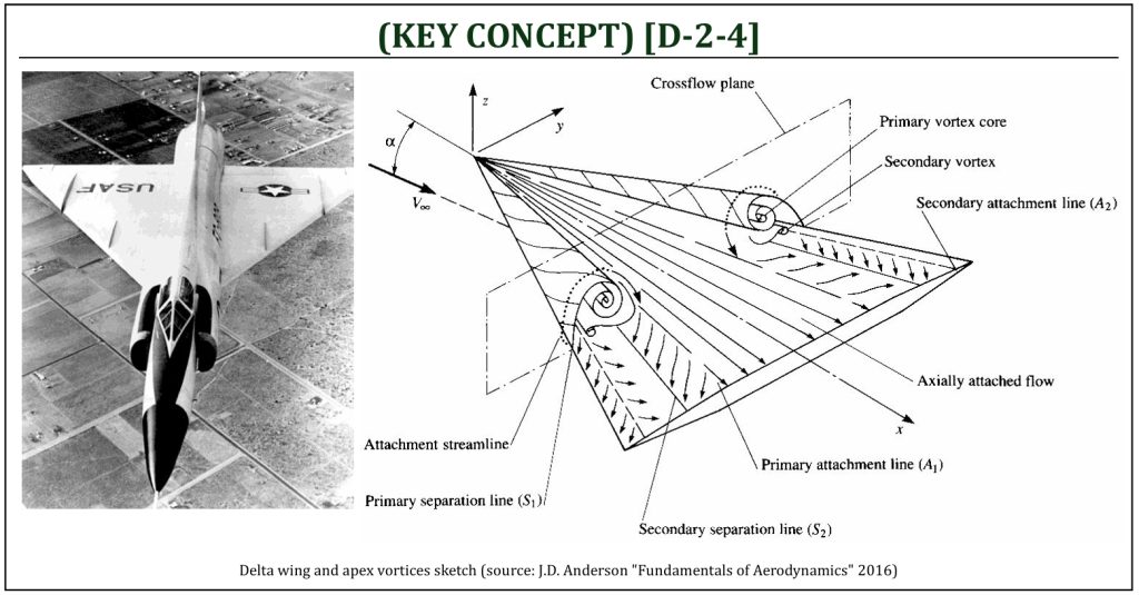
The delta wing is a special case of highly swept wing with extremely low aspect ratio. The original design of delta wings was pioneered in Germany and the Soviet Union prior to WWII. After the war, the tail-less delta became the favored design for a high-speed aircraft, and was extensively used by Convair (Delta series) in the U.S. and Dassault (Mirage series) in France. The primary advantage of the delta wing design is similar to that of swept wings. The critical Mach number (Mcr) is delayed to a much higher value, and the drag in transonic and supersonic flights will be reduced. Also, the delta wing’s planform carries across the entire aircraft, allowing it to be built much more strongly than a conventional wing with sweep, where the spar meets the fuselage far in front of the center of gravity (CG) location. In general, a delta wing will be stronger than a similar swept wing, and also having much more internal volume for fuel and other storage.
The delta wings at subsonic speed generate a pair of strong leading edge vortices as the angle of attack increases (called “delta wing apex vortices“). This pair of vortices remains attached to the upper surface of the wing, giving the delta a very high stall angle of attack (αstall). A normal wing built for high speed use (imagine, F-104) is typically dangerous at low speeds, but in this regime the delta changes over to a mode of lift based on the vortex it generates. The disadvantages, especially marked in the older tailless delta designs, are a loss of total available lift caused by turning up the wing trailing edge or the control surfaces (as required to achieve a sufficient stability) and the high induced drag of this low-aspect ratio type of wing.
The leading edge vortices are fairly steady over a wide range of angle of attack, supporting the lift force of the delta wing. The surface pressure on the top surface of the delta wing is reduced near the leading edge and is higher and reasonably constant over the middle of the wing. The spanwise pressure coefficient distribution is modified by the presence of strong vortices: this is the main mechanism of delta wings for enhances lift at high angles of attack. A leading edge vortex flap (LEVF) further enhances the lift and increases the lift-to-drag ratio of a flat delta wing.
The delta wing leading edge vortices can easily be visualized in water tunnel. Smooth streaklines of a low Reynolds number flow field can clearly be seen by injecting food coloring dye into the flow. This pair of strong counter-rotating delta wing apex vortices sustain in a wide variety of angles of attack in delta wings. Under a certain flow condition, the pair of leading edge vortices of delta wing starts to fluctuate and “burst.” This is called, the delta wing “vortex breakdown.” The vortex breakdown means the sudden loss of lift (associated with stall condition during flight). Some early delta wings tend to have this breakdown induce stall, associated with the deployment of wing trailing edge control surfaces flaps, for example). This caused many issues in stability and control of aircraft, and disadvantages especially in aerial combat maneuvering. One common solution to fix this problem is to combine delta wings with canards.
References
- U.S. Air Force (https://www.airforce.com)
- The Boeing Company (https://www.boeing.com)
- NASA (www.nasa.gov)
- BoldMethod (www.boldmethod.com)
- J.S.M. Guerrero & K. Wittkowski “CFD Study of the impact of variable cant angle winglets on total drag reduction” Aerospace, 2018
- M. Mrazova “Innovations, technology, and efficiency shaping the aerospace environment” INCAS Bulletin, 2013
- Fundamentals of Aerodynamics by J.D. Anderson, 5th ED, McGraw Hill, 2016
- Aerodynamics for Engineers by J. J. Bertin & M. L. Smith, 3rd ED, Cambridge University Press, 1997
- Aerodynamics for Engineering Students by E. L. Houghton & P. W. Carpenter, 4th ED, Edward Arnold, London, 1993
Media Attributions
If a citation and/or attribution to a media (images and/or videos) is not given, then it is originally created for this book by the author, and the media can be assumed to be under CC BY-NC 4.0 (Creative Commons Attribution-NonCommercial 4.0 International) license. Public domain materials have been included in these attributions whenever possible. Every reasonable effort has been made to ensure that the attributions are comprehensive, accurate, and up-to-date. The Copyright Disclaimer under Section 107 of the Copyright Act of 1976 states that allowance is made for purposes such as teaching, scholarship, and research. Fair use is a use permitted by copyright statute. For any request for corrections and/or updates, please contact the author.
