D-1: Aerodynamics of Wings (1)
Aerodynamics of 3-D Finite Wings (1 of 2)
Shigeo Hayashibara
Infinite v.s. finite wings
Airfoil and Finite Wing
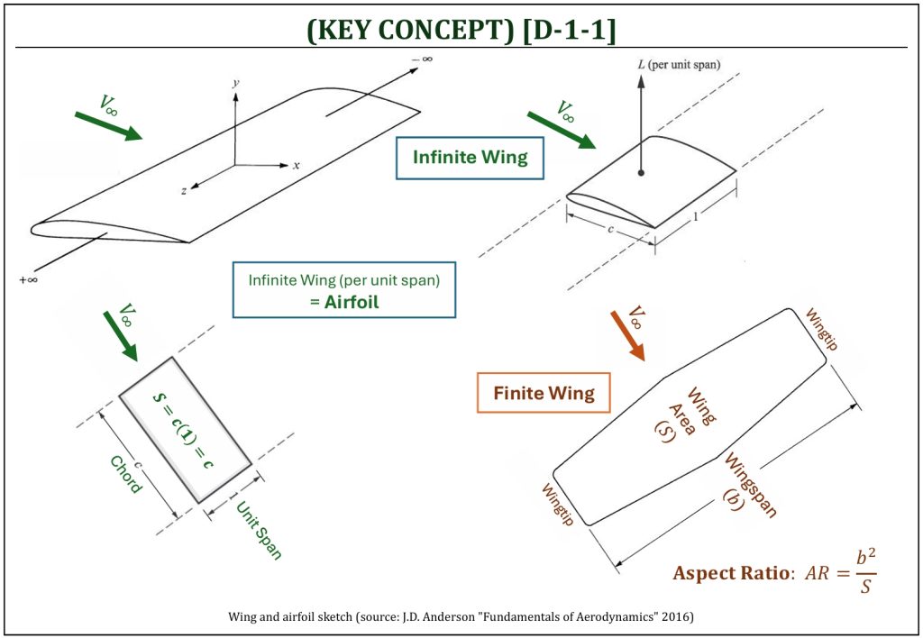
Let us imagine an “infinite” wing (wing span stretches infinity with a constant cross-sectional shape). An airfoil is defined as a “per unit span” geometry of this infinite wing. An airfoil provides section characteristics (2-D) of a finite wing (3-D). Again, imagine a design analysis of a finite wing (3-D). If it is possible to analyze and characterize each cross-section (airfoil) of this wing, it is possible to predict characteristics of this wing as an “integrated results” of each cross-section (airfoil) parameters. This is the fundamental concept of computer simulation based design analysis of a finite wing (3-D).
As a finite wing (3-D) is designed, it is possible to introduce many varieties of spanwise shape modifications. The simplest possible wing design (called, the “Hershey’s-Bar” wing design) is a rectangular shape with constant cross-section. The only design parameter will be the Aspect Ratio (AR). Two common spanwise shape modifications for a 3-D wing design are:
- Geometric twist of a wing is varying angle of attack along the span but retains the same airfoil (wash “in” or “out“).
- Aerodynamic twist of a wing is varying airfoil (cross section of the wing) along the span but retains the angle of attack.
Wing washout
Wing Washout and Stall Recovery
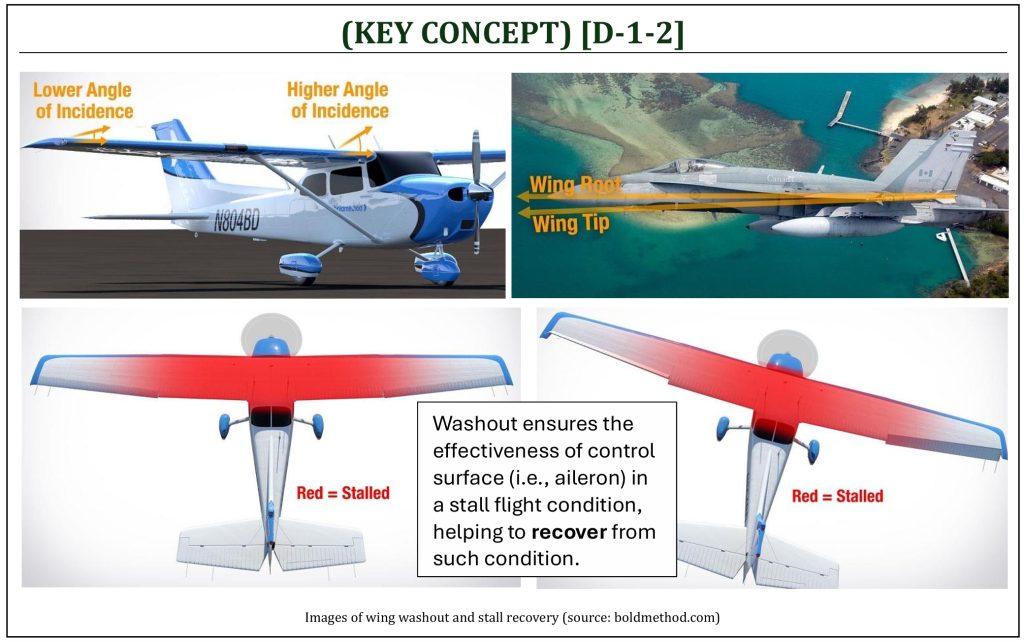
At first glance, it looks like aircraft wings are straight across the wingspan, especially for a lightweight aircraft (i.e., Cessna 172) with a straight rectangular wing. However, almost all aircraft have wing “washout” built into the wing. The angle of incident is lower at the root of a wing, while the angle of incident is slightly higher at the wingtip. The reason is that the control surface (i.e., aileron) is usually at the wingtip of the wing. The root of the wing will experience a higher angle of attack (α) than the wingtip always. When an aircraft is at a near-stall flight condition, it is always desired that the root of the wing (not the wingtip) stalls first. When an aircraft stalls at the root of the wing first, it means that there would still be enough airflow over the wingtip to prevent ant rapid rolling motion during a stall. This makes an aircraft more stable at the near-stall condition (more resistance against entering a “spin“). Also, a root stall ensures some aileron effectiveness during the stall, it provides spin recovery control capability, especially during a banked turning flight. If the aircraft does not have washout, it would cause the entire wing stall at once, or even would cause the wingtip stall (i.e., the instantaneous loss of aircraft control).
Wingtip Vortices and Induced Drag
Wingtip Vortices and Change of Local Flow Direction of a Wing
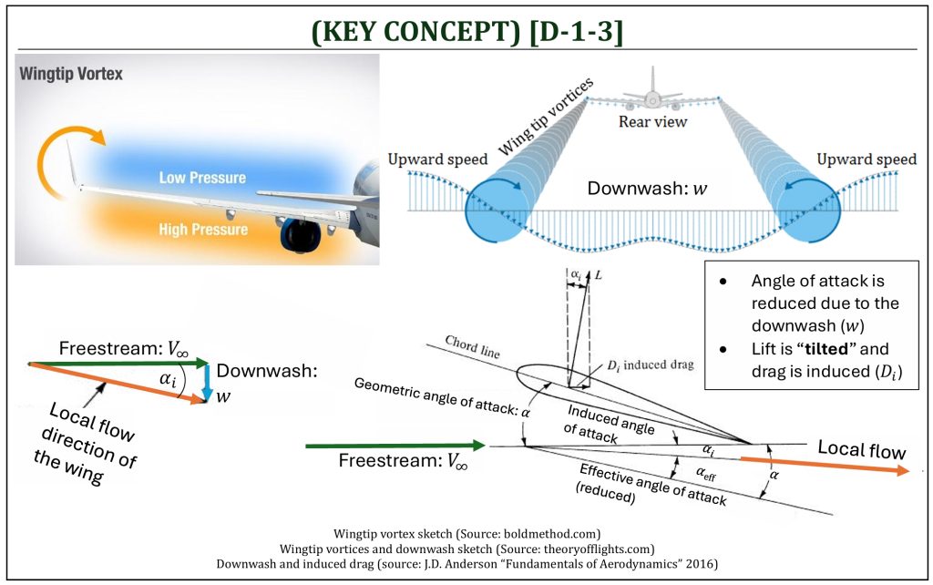
For a finite wing, the pressure difference between top and bottom surfaces of wing causes a pair of trailing circular motion flows, called the “wing tip vortices.” The wing tip vortices tend to drag the surrounding air, and this secondary movement induces a small velocity component in the downward direction at the wing, called the “downwash” (w). The existence of downwash creates an additional drag on wings that cannot be expected on 2-D airfoil (called, the “induced drag“). Even if a careful and detailed design (selection of 2-D airfoil) is completed, one can still do a poor job designing a 3-D wing (may result in very high induced drag). The quality of wing performance depends on how to minimize the induced drag by carefully designing a 3-D shape of the wing. Induced drag will typically depend on:
-
Aspect Ratio (AR) of the wing
-
How efficient is your wing (called, the “span efficiency factor“), in which depends on wing’s taper, sweep, wingtip design, twist, dihedral, etc. etc.
-
Lift coefficient (CL) of the wing: IRONICALLY . . . if the wing produces more lift, it actually also increases the induced drag . . . hence, the induced drag is often called, the “drag due to lift” (a portion of the lift turns directly into the drag).
In summary, the downwash (w) generated by the wing tip vortices will have several important consequences for a 3-D wing:
-
Angle of attack of the airfoil sections of the wing (defined as the “effective” angle of attack: αeff) is now referenced from the local flow direction, which is effectively reduced by the amount of αi (called the “induced” angle of attack) in comparison to the “geometric” angle of attack of the wing (α) referenced to the freestream (V∞).
-
There is an introduction to a new component of aerodynamic drag, called the “induced drag.” Because of the local relative wind is tilted downwards, the lift vector itself is tilted backwards, hence it contributes a certain component of force parallel to the freestream (V∞). This component of lift now becomes a drag: this is a “drag due to lift” (induced drag).
Induced Drag (Drag due to Lift)
3-D wing spanwise lift distribution typically depends on the following wing design parameters (obviously at each wingtip, lift will become zero):
- Varying the chord length along the span (wing “taper“)
- Varying the angle of attack along the span (“geometric twist“)
- Varying the airfoil along the span of the wing (“aerodynamic twist“)
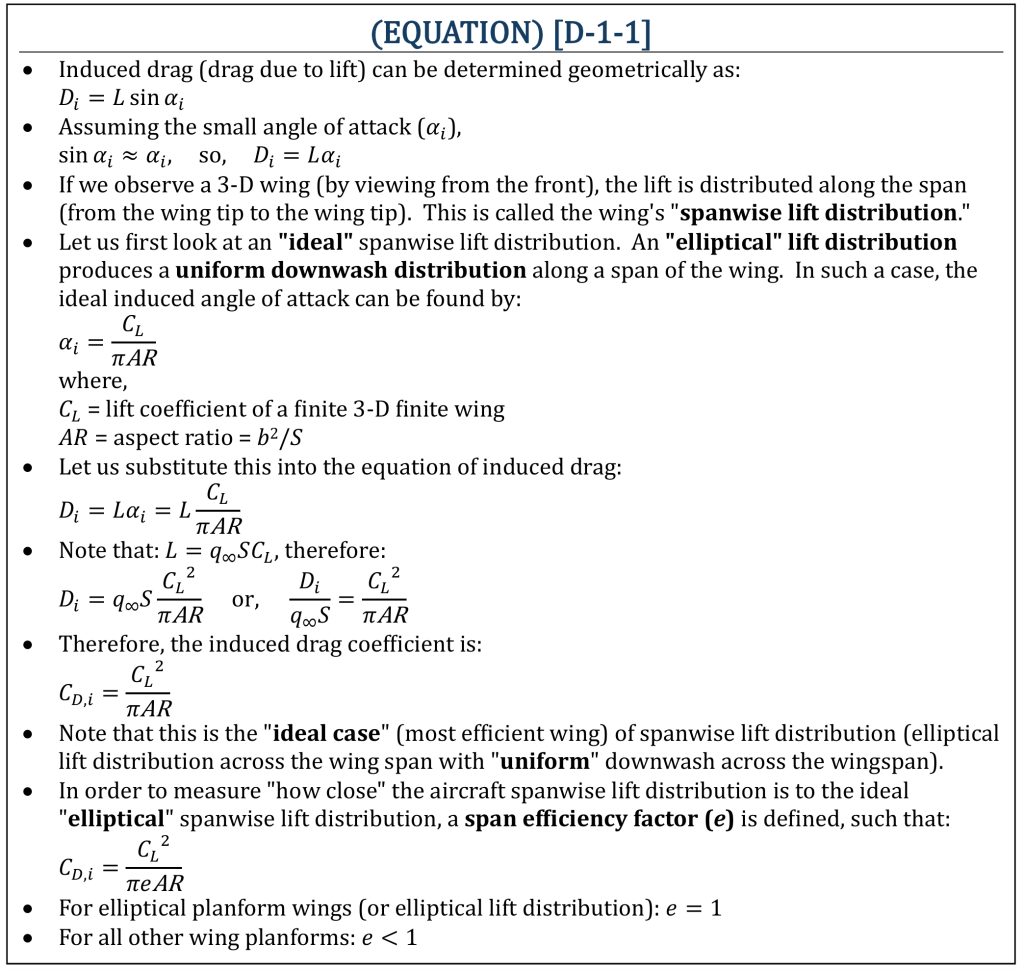
An “elliptical” lift distribution (means that the shape of the lift distribution is mathematically the equation of ellipse) produces a uniform downwash distribution along a span of the wing (the ideal case of lift distribution). An elliptical lift distribution can “potentially” be achieved by having an elliptical wing planform. However, not all airplanes can have elliptic planform shape. Also, the presence of a fuselage usually prohibits such an ideal spanwise lift distribution (a pure “elliptical” lift distribution is nearly impossible to achieve in reality).
The drag of a finite wing
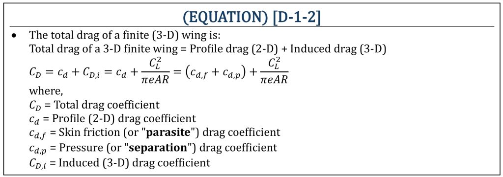
Total Drag of a 3-D Finite Wing
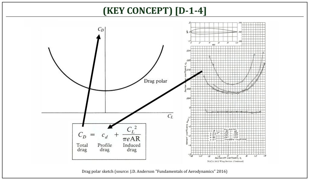
When a total drag is determined for a finite 3-D wing, it is important to include all contributing components of drags. The induced drag (CD,i) is often called the “drag due to lift” (3-D effect) and can only determine after the 3-D wing geometry is defined. The profile drag (cd) is a drag on a 2-D airfoil, from which includes: (i) skin friction drag (also called the “parasite” drag) and (ii) pressure drag (also called the drag “due to flow separation“).
Total Drag Coefficient
The plot of lift coefficient (CL) v.s. drag coefficient (CD) is commonly called the “drag polar” plot and it indicates an important relationship between lift and drag, as follows:
-
The drag polar provides important information of how much drag is associated with a given increase of lift.
-
In aircraft design, usually several varieties of drag polar plots will need to be presented (i.e., clean, flap up or down, gear up or down for take-off and/or landing configurations).
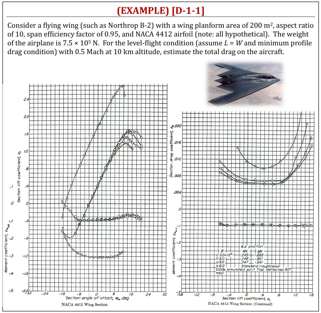
Estimated Total Drag of a Finite 3-D Wing
The lift of a finite wing
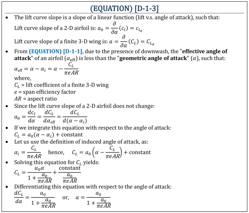
Lift Curve Slope of Airfoil (2-D) v.s. Finite Wing (3-D)
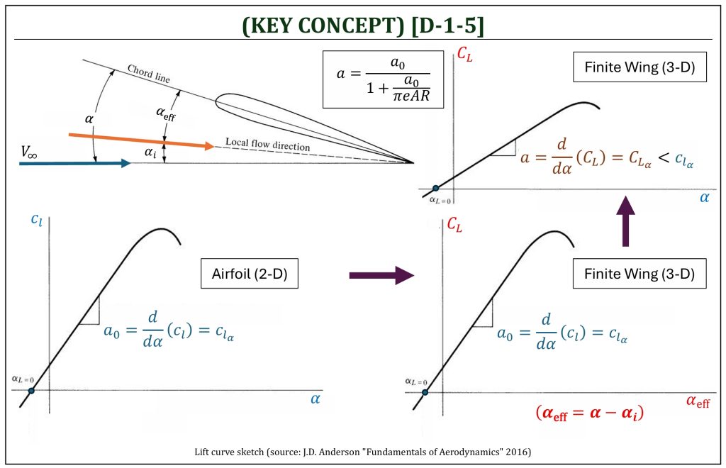
The lift coefficient of a finite 3-D wing is also not the same against the lift coefficient of a 2-D airfoil. The existence of downwash (w) induces another negative side effect on a finite 3-D wing. The change of local flow direction, due to downwash, will reduce the “geometric” angle of attack (α) into the lower angle, called the “effective” angle of attack (αeff). If the lift coefficient of a finite 3-D wing (CL) is plotted against the geometric angle of attack, therefore, the lift curve slope (a) becomes lower value than it was expected in a 2-D airfoil (a0). For a “thin” airfoil, the lift curve slope of a 2-D airfoil is 2π (1/rad) or 0.1097 (1/deg).
Change in the Lift Curve (1)
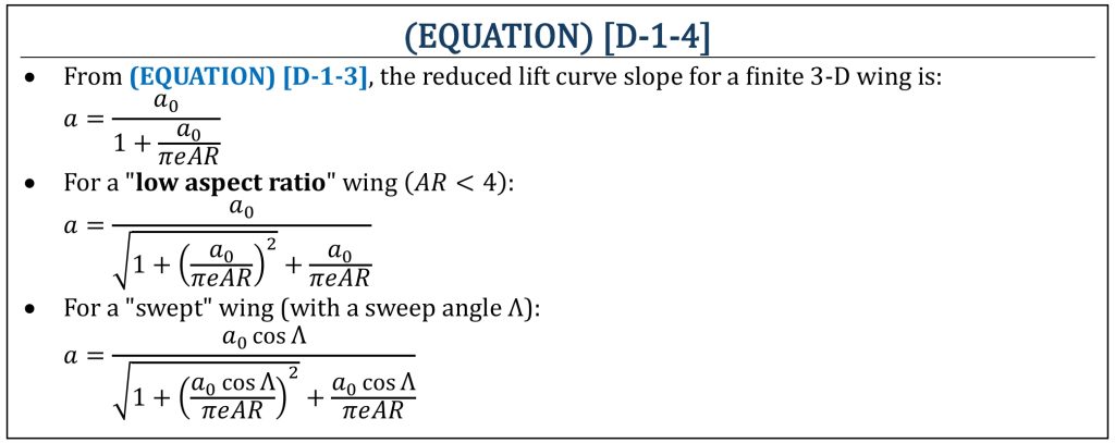
Further, the reduction of the lift curve slope will be affected by the presence of wing sweep and also the design of extremely “low” aspect ratio (AR < 4). Often, the wing sweep and low aspect ratio wing design is desired for a high-speed aircraft. However, these will be associated with the reduced lift curve slope of a wing, resulting in a poor low-speed performance of an aircraft.
Change in the Lift Curve (2)
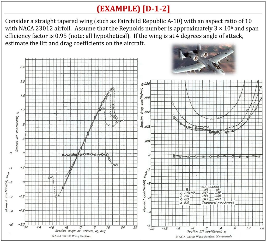
Estimated Lift and Drag of a Finite 3-D Wing
References
- NASA (www.nasa.gov)
- BoldMethod (www.boldmethod.com)
- Theory of Flights (https://theoryofflights.blogspot.com)
- Aeronautical Lecture Note (https://aeronauticallecture.blogspot.com)
- Fundamentals of Aerodynamics by J.D. Anderson, 5th ED, McGraw Hill, 2016
- Aerodynamics for Engineers by J. J. Bertin & M. L. Smith, 3rd ED, Cambridge University Press, 1997
- Aerodynamics for Engineering Students by E. L. Houghton & P. W. Carpenter, 4th ED, Edward Arnold, London, 1993
Media Attributions
If a citation and/or attribution to a media (images and/or videos) is not given, then it is originally created for this book by the author, and the media can be assumed to be under CC BY-NC 4.0 (Creative Commons Attribution-NonCommercial 4.0 International) license. Public domain materials have been included in these attributions whenever possible. Every reasonable effort has been made to ensure that the attributions are comprehensive, accurate, and up-to-date. The Copyright Disclaimer under Section 107 of the Copyright Act of 1976 states that allowance is made for purposes such as teaching, scholarship, and research. Fair use is a use permitted by copyright statute. For any request for corrections and/or updates, please contact the author.
