16 Your First Network
Mathew J. Heath Van Horn, PhD
A user’s experience with network devices varies widely. Gamers are probably familiar with port forwarding on their home router, but may not understand why these actions are needed. Others may have never been interested in how the magic network box in their home works.
This exercise helps all users get familiar with using the GNS3 environment. We used a typical home environment because some users have probably encountered this type of setup before. However, our testers found that even the most novice users could follow these instructions to gain an understanding of using GNS3.
We had to take some liberties since many home network devices are all-in-one solutions, but learners should focus on using the tools and not how close it resembles “real life”.
Estimated time for completion: 15 minutes
Learning Objectives
- Create a typical home network in the GNS3 network
- Become familiar with labels and symbols in the GNS3 network
Prerequisites
- Chapter 2 – Setting Up a GNS3 Environment
- Chapter 4 – Installing an OpenWRT Router
- Chapter 6 – Adding a Virtual Machine to GNS3
Deliverables
- One screenshot of the completed GNS3 Environment
Resources
- N/A
Contributors and testers
- TBD
Phase I – Background Information
This LAB is designed to resemble a typical home network. Some adjustments will need to be made because you are unable to see the device or the wireless signals. So, we will take this opportunity to familiarize you with the setup and then you can add your own devices.

The typical all-in-one device in this lab is split apart for better visualization. Remember, a home or small business Internet access point is typically an all-in-one device. One physical box contains the modem, router, switch, and wireless access point. The figures below compare a typical home environment with our lab environment. The details are unimportant to most people, but you aren’t most people; you want to understand how these components work together. Look at both images, the left image is an all-in-one device, but the right one splits the components into individual components. You can trace the Internet route from the ISP to the PC in both images.

Phase II – Setup
These steps are necessary to prepare the playing field. There are quite a few of them, but they are simple. Complete them one at a time, and you will have a working learning environment in no time.
- Start the GNS3 application
- Create a new project
- Start by clicking File > New Blank Project on the upper left-hand side
- For this example, we are using the name LAB_01, but you can name your lab anything you like
- Select OK
- Under the Servers Summary section in the bottom-left-hand corner of the workspace, verify that both the host machine and GNS3 VM are connected by looking for the two green lights

Figure 3 – GNS3 Working Environment is ready to go NOTE: This can take some time depending on the hardware being used. It will be gray before it turns green. If the VM does not start automatically, restart GNS3 and click Help > Setup Wizard to reestablish the link to VirtualBox as outlined in Chapter 2. Do not manually start the GNS3 VM before launching GNS3.
- Connect the OpenWrt router to your simulated ISP
- Complete Chapter 4
- On the left side of the GNS3 environment, you can see various tools. Click on Browse all devices as shown here
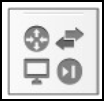
- A sub-menu will appear. Click the picture of a cloud with the word NAT next to it and drag it to the workspace

Figure 4 – Device icons 
Figure 5 – Add a NAT cloud to GNS3 NOTE: Whenever you are asked to choose a server, use the dropdown menu to select the GNS3 VM (GNS3 VM) option.
- Change the name from “NAT1” to “ISP” by double-clicking on the name and pressing OK

Figure 6 – Change NAT cloud name to ISP - Again, click on the Browse all devices
- Drag the device called OpenWrt to the workplace

Figure 7 – add OpenWRT router - The default symbol for the OpenWrt router is the universal symbol for routers, but it can be hard to see at times. Change the symbol by right-clicking on the router and then selecting Change Symbol on the menu

Figure 8 – Changing the Router Symbol - Select the Affinity-square-red option and look for the router symbol, then click on OK

Figure 9 – Select the red router symbol - Double-click on the router name and change it from “OpenWrt-1” to “Router“
- Add a network switch
- Click on the Browse all devices button again
- This time, drag the Ethernet switch to the workspace
- Use the GNS3 VM to host the switch
- Rename the device to “Switch”
- Change the symbol to the Affinity-square-red option for the switch, by right-clicking on the switch and selecting the change symbol option. The workspace should now look similar to the following

Figure 10 – add a switch
- Add a VM with an Internet browser
- Add a VM to GNS3 (we are using Ubuntu Mate, but any VM with a browser should work)
- Allow GNS3 to configure VirtualBox network settings
- Go to File > Preferences
- Navigate to the VirtualBox VMs section
- Double-click on your imported VM
- Under the Network tab, check the box that says Allow GNS3 to use any configured any VirtualBox adapters
- Rename the device to “PC” and your workspace should look like the following

Figure 11 – the network built so far NOTE: We generally use GNS3’s built-in virtual personal computer simulators (VPCS) because using too many VirtualBox VMs can drag down your system’s performance. However, the VPCS does not have a browser to use the GUI interface of the OpenWrt router.
- Link the devices together
- Return to the GNS3 workspace
- On the left side of the GNS3 workspace, click on the Add a link button

- Click on the ISP cloud and then click on the nat0 port in the sub-menu

Figure 12 – Select NAT interface - Click on the Router and then select the Ethernet1 port in the sub-menu. It is VERY IMPORTANT that this cable is connected to port Ethernet1. This is like plugging (screwing) in a cable from the ISP to your home router/switch/modem port that is commonly labeled “Internet”
- Click on the Router and then click on the Ethernet0 port in the sub-menu. This is like plugging a cable into your home router/switch/modem port that is commonly labeled “1” or “PC”
- Click on the switch and select any red (unused) port
- Now, click on the switch and select another unused port and attach it to the PC’s Ethernet0 port
- Show the interface labels by clicking on the Show/Hide interface labels button

- Your workspace should now look like the following

Figure 13 – All devices connected NOTE: Notice that some of the ends show red; this means that the device is turned off or the interface has been disabled.
- Now, press the big green arrow to start all the devices
 . All cable points should eventually turn green as all the devices boot up

Figure 14 – all connections are green
Phase III – Interface with the Home Router
Most home routers are configured by using a PC or laptop. We are going to use our virtualized PC to do the same thing.
- Navigate to your VM instance on your Windows taskbar and log in. Remember, in this example, we are using Ubuntu Mate

Figure 15 – Ubuntu Mate - Access the OpenWrt router management webpage
- Open a browser application (ex. Firefox)
- In the navigation bar type 192.168.1.1 and press Enter
NOTE: Most home routers have a default access login of 192.168.1.1. A piece of trivia you might want to file away for your future pentesting efforts!
- You should be at the OpenWrt GUI interface

Figure 16 – Web interface for OpenWRT - The username is “root” and there is no password, so just click Login
- It will take you to the status overview section. You can scroll through this information and see that devices are connected to the router. The network information is the ISP, and the DHCP leases show the VM you are using now

Figure 17 – OpenWRT network leases - If you click around on the OpenWrt router, you can see it has many of the same settings as a Linksys or TP-Link router. Don’t change any settings at this time. We want to add more devices
Phase IV – Add More Devices to the Home Network
Rarely do home networks have only a single device. So we are going to add a few more.
- Click on the Browse all devices button and drag a VPCS device to the workspace

Figure 18 – Add a VPCS NOTE: This device is very lightweight and does not require nearly as many resources as a VirtualBox VM. Don’t forget to use the GNS3 VM when asked
- Use the techniques learned earlier and make the following changes
- Change the VPCS symbol to a laptop
- Change the name to “Laptop”
- Connect a cable from the laptop to the switch

Figure 19 – Changing to laptop
- Laptops are typically wireless, so let’s change the connecting line to reflect this
- Right-click on the cable and select Style
- On the submenu change the border style to Dash Dot Dot.
- Press Apply and OK to close the submenu
- Turn on the laptop by right-clicking and selecting Start
- Add the laptop to the network
- Right-click on the laptop and click on Console
- Read the opening statements. Note that if you get lost, you can always enter the question mark to get assistance
- At the prompt type the following command to request an IPv4 address and press Enter
> ip dhcp
- After a few seconds, you will get a message reporting which IP address was assigned

Figure 20 – VPCS (laptop) showing DHCP connection NOTE: If you get lost, you can always enter a question mark [?] to get assistance such as available commands and their syntax.
- While there is no browser application to open, you can still test Internet connectivity via the ping command
> ping www.google.com

Congratulations!
You have built your first network in GNS3!
End of Lab
Deliverables
One screenshot is needed of your GNS3 environment:
- Click on the Add a note button at the top of the workspace and put your name, class, and section on your workspace

- Select the Take a screenshot button to save a screenshot of your workspace and submit it per the instructor’s instructions to receive credit for completing this activity

- Example output…

Figure 22 – Example
Homeworks
Assignment 1 – Add more devices
- Add another VPCS and change the label connection and picture to resemble a Cell Phone
- Add another VPCS and change the device’s label and picture to resemble a desktop printer
- RECOMMENDED GRADING CRITERIA
- Screenshot of the new GNS3 working environment with everything labeled