28 Static Networking Part 2
Jacob Christensen and Kyle Wheaton
Up to this point, we have been using one router in our working environments that use DHCP. However, you will rarely work on a network with only one router because the whole point of an enterprise network is to connect multiple LANs into a single cohesive network.
In this lab, we will create and connect three LANs via three routers. We introduce you to static routing solutions so you can become familiar with routing procedures. Static routing is impractical mainly because it is very manpower intensive to maintain and prone to human error.
Estimated time for completion: 60 minutes
Learning objectives
- Successfully create three functional LANs:
- Gray (DHCP Server)
- Red (Switch + 2 PCs)
- Blue (Switch + 2 PCs)
- Configure three routers to use static routing so all devices can communicate
Prerequisites
Deliverables
4 screenshots are required to receive credit for this lab
- Screenshot of GNS3 workspace with everything labeled
- Screenshot of the DHCP configuration
- Wireshark Screenshots of a Red host successfully pinging:
- Blue Host
- Gray Host
Resources
- MikroTik RouterOS Documentation – IP Routing – https://help.mikrotik.com/docs/display/ROS/IP+Routing
Contributors and Testers
- Dante Rocca, Cybersecurity Student, ERAU-Prescott
Phase I -Building the Topology
The following steps are to create the baseline for completing the lab. It makes assumptions about learner knowledge from completing previous labs. To reduce the amount of stress on the PC, we will be using Linux boxes for DHCP.
By the end of this chapter, your network should look like the following:

- Open GNS3
- Create a new project and name it whatever you like. We named ours Lab 28
- Build a small network with the following specifications
- Class B Supernet – 10.0.0.0/16
Host Range Host Lower Bound 10.0.0.1 Host Upper Bound 10.0.255.254 NOTE: Our supernet is the total IP address space we are allowed to use for this network. We will subnet this as necessary to fit our needs for each LAN. If you still confused how subnetting works, there are plenty of online tools that can help augment your learning!
- Subnet – Red
- One switch – Ethernet switch
- Two client machines – VPCS
- Minimize wasted address space for 300 hosts
Network Information Network 10.0.0.0 Netmask 255.255.254.0 (/23) Broadcast 10.0.1.255 Gateway 10.0.0.1 DHCP Lower Bound 10.0.0.100 DHCP Upper Bound 10.0.1.250 NOTE: I am choosing to reserve the first usable host for my gateway addresses. In addition, my DHCP range does not include every single host address available (mostly because I like clean numbers). These are not hard and fast rules. Feel free to adjust as necessary.
- Subnet – Blue
- One switch – Ethernet switch
- Two client machines – VPCS
- Minimize wasted address space for 150 hosts
Network Information Network 10.0.2.0 Netmask 255.255.255.0 (/24) Broadcast 10.0.2.255 Gateway 10.0.2.1 DHCP Lower Bound 10.0.2.100 DHCP Upper Bound 10.0.2.250
- Subnet – Gray
- One DHCP server – Ubuntu 22.04.X LTS
NOTE: In this example, the server will have a static IP address of 10.0.3.6.
- Minimize wasted address space for 6 hosts
Network Information Network 10.0.3.0 Netmask 255.255.255.248 (/29) Broadcast 10.0.3.7 Gateway 10.0.3.1
- One DHCP server – Ubuntu 22.04.X LTS
- Subnet – Backbone
- Three routers – MikroTik CHR
- Full-mesh topology
NOTE: The term full-mesh simply means that each node is connected to every other node.
- Minimize wasted address space for each router-to-router connection
Connection Network Router1 <-> Router2 10.0.4.0/30 Router1 <-> Router3 10.0.5.0/30 Router2 <-> Router3 10.0.6.0/30
- Class B Supernet – 10.0.0.0/16
- Connect each LAN to its own router
- Label and organize your network as necessary

Figure 2 – GNS3 working environment
Phase II – Configuring the Backbone Network
Before any of the clients can receive IP addresses, we need to ensure that the routers can communicate with each other. This phase will focus on configuring MikroTik routers and establishing static routes.
- Login to Router1 and open its console
- Set static IP addresses for all active network interfaces

Figure 3 – Set static addresses for each interface Interface Network IPv4 Address ether1 -> Red 10.0.0.0/23 10.0.0.1 ether2 -> Router2 10.0.4.0/30 10.0.4.1 ether3 -> Router3 10.0.5.0/30 10.0.5.1 NOTE: Refer to Chapter 18, Phase II for additional information on how to configure IP address in MikroTik.
- Configure Router1 to act as a relay for the DHCP discover packets

Figure 4 – Set the router for DHCP relay traffic > ip dhcp-relay add name=Red-Relay interface=ether1 dhcp-server=10.0.3.6 local-address=10.0.0.1 disabled=no
NOTE: You only need to configure DHCP forwarders for networks directly connected to the relay. In this case, only the Red subnet is attached to this router, so only one relay needs to be made. Refer to Chapter 24, Phase II for additional information.
- Statically update Router1’s routing table with routes to the Blue and Gray networks

Figure 5 – Add routes to Blue and Grey networks NOTE: Two routes need to be created for every subnet, with each specifying the same destination via different gateways (Router2 and Router3). This is a form of redundancy that ensures network functionality even in the event that either path goes offline. When building networks, it is essential to minimize single points of failure to ensure maximum availability and reliability. For example, these two commands would be used for the RED router:
“Any packets from the red network needing to go to the blue network, send them to Router2.”
> ip route add dst-address=10.0.2.0/24 gateway=10.0.4.2 distance=1
“Any packets from the red network needing to go to the blue network, send them to Router3, which will forward the packets to Router2.”
> ip route add dst-address=10.0.2.0/24 gateway=10.0.5.2 distance=2
- Add all routes to the Blue subnet
> ip route add dst-address=10.0.2.0/24 gateway=10.0.4.2 distance=1
> ip route add dst-address=10.0.2.0/24 gateway=10.0.5.2 distance=2
NOTE: The distance option specifies the number of additional routers required to reach the destination network. The route with the shortest number of hops will take priority over the other. This is another reason people do not use static networking, as dynamic networking performs this calculation automatically.
- Add all routes to the Gray subnet
> ip route add dst-address=10.0.3.0/29 gateway=10.0.5.2 distance=1
> ip route add dst-address=10.0.3.0/29 gateway=10.0.4.2 distance=2
- Add all routes to the Blue subnet
- Set static IP addresses for all active network interfaces
- Login to Router2 and open its console
- Set static IP addresses for all active network interfaces

Figure 6 – Set static IPs for router 2’s interfaces Interfaces Network IPv4 Address ether1 -> Blue 10.0.2.0/24 10.0.2.1 ether2 -> Router1 10.0.4.0/30 10.0.4.2 ehter3 -> Router3 10.0.6.0/30 10.0.6.1 - Configure Router2 to act as a relay for DHCP discover packets

Figure 7 – Set router 2 to act as a DHCP relay > ip dhcp-relay add name=Blue-Relay interface=ether1 dhcp-server=10.0.3.6 local-address=10.0.2.1 disabled=no
- Statically update Router2’s routing table with routes to the Red and Gray networks
- Add all routes to the Red subnet
> ip route add dst-address=10.0.0.0/23 gateway=10.0.4.1 distance=1
> ip route add dst-address=10.0.0.0/23 gateway=10.0.6.2 distance=2
- Add all routes to the Gray subnet
> ip route add dst-address=10.0.3.0/29 gateway=10.0.6.2 distance=1
> ip route add dst-address=10.0.3.0/29 gateway=10.0.4.1 distance=2

Figure 8 – Add routes to Red and Grey networks on router 2
- Add all routes to the Red subnet
- Set static IP addresses for all active network interfaces
- Login to Router3 and open its console
- Set static IP addresses for all active network interfaces
Interfaces Network IPv4 Address ether1 -> Gray 10.0.3.0/29 10.0.3.1 ether2 -> Router1 10.0.5.0/30 10.0.5.2 ether3 -> Router2 10.0.6.0/30 10.0.6.2 NOTE: We will not configure any DHCP relays on this device since there is no DHCP-dependent LAN that is directly connected to it. The Gray subnet will only consist of statically assigned host addresses.

Figure 9 – Set static IPs on router 3 - The Gray Network does not have to request DHCP addresses through a router. Therefore, there is no need to set up a DHCP relay
- Statically update Router3’s routing table with routes to the Red and Blue networks
- Add all routes to the Red subnet
> ip route add dst-address=10.0.0.0/23 gateway=10.0.5.1 distance=1
> ip route add dst-address=10.0.0.0/23 gateway=10.0.6.1 distance=2
- Add all routes to the Blue subnet
> ip route add dst-address=10.0.2.0/24 gateway=10.0.6.1 distance=1
> ip route add dst-address=10.0.2.0/24 gateway=10.0.5.1 distance=2

Figure 10 – Add routes to Red and Blue network on router 3
- Add all routes to the Red subnet
- Set static IP addresses for all active network interfaces
- Verify that all three routers can ping each other before continuing to the next section
Phase III – Configure the DHCP Server
Now that the network is set up, we can configure our server and test the reliability of the routes.
- Start the DHCP server and login
- Configure the network interface with the static IPv4 address 10.0.3.6
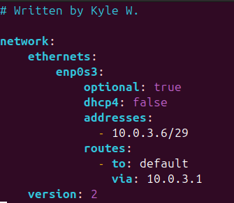
Figure 11 – Static IP on DHCP relay server - Modify the DHCP daemon configuration file to support the Red and Blue networks
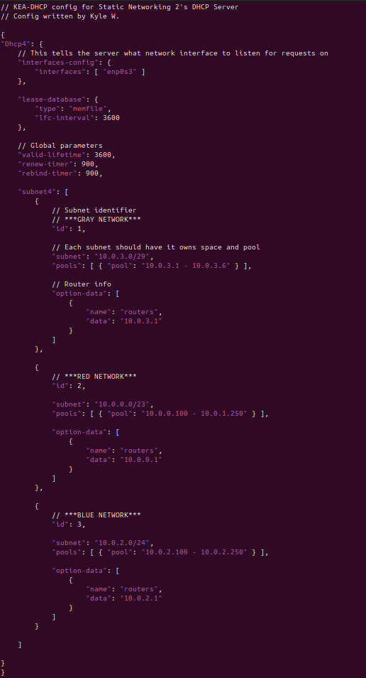
Figure 12 – KEA DHCP support for Red and Blue networks
- Configure the network interface with the static IPv4 address 10.0.3.6
- Start PC1 and open its console
- Test the DHCP service by requesting a new IP address
> ip dhcp
- Test the reliability of the network by cutting the Router1-Router3 link

Figure 13 – Cut wire in network - Request a new IP address
> ip dhcp
- Test the DHCP service by requesting a new IP address
- Repeat step 2 with a client device from the Blue network
NOTE: Try cutting the Router2-Router3 link instead. We are trying to see if the routers can successfully redirect packets via the longest path!
Congratulations! You were able to create small network with multiple routers by manually administering the routing tables. Hopefully by the end of this exercise you realize how tedious and error-prone this can be as network sizes increases. Luckily, the next few chapters will introduce new protocols that can automate this process for a much friendlier experience
End of Lab
Deliverables
4 screenshots are required to receive credit for this lab
- Screenshot of GNS3 workspace with everything labeled
- Screenshot of the DHCP configuration
- Wireshark Screenshots of a Red host successfully pinging:
- Blue Host
- Gray Host
Homeworks
Assignment 1 – Add another LAN and router to our enterprise
- Add a Green network to the enterprise
- It is projected to use 73 hosts
- The new router needs to connect to both Router1 and Router2 for redundancy
- The Green network needs to get DHCP addresses from the DHCP server
- Hint: don’t forget to update the old routers with new paths as well!
- RECOMMENDED GRADING CRITERIA
- Screenshot of GNS3 Workspace with all devices labeled
- Screenshot of the DHCP configuration
- Wireshark Packet Captures where a Green host can ping
- Red Host
- Blue Host
- Gray Host
- Sample network environment:

Figure 14 – Assignment 1 network
Assignment 2 – Create a full mesh network
- Building off of Assignment 1
- Add a Purple network to the enterprise
- It is projected to use 600 hosts
- Add network paths so each router has a link to every other router. (e.g. as it stands, Router3 has no direct connection to Router4)
- RECOMMENDED GRADING CRITERIA
- Screenshot of GNS3 Workspace with all devices labeled
- Wireshark capture on the following links showing that an ICMP packet from a Blue host takes different paths to reach the Purple host (You may have to disconnect some connections to force the change in path)
- Router1 <-> Router5
- Router2 <-> Router5
- Router3 <-> Router5
- Router4 <-> Router5
- Sample network environment:

Figure 15 – Assignment 2 network