29 Dynamic Networking – Routing Information Protocol
Jacob Christensen and Mathew J. Heath Van Horn, PhD
As demonstrated in the previous lab, routers need to be told about distant networks in order to communicate with devices 1+ hops away. Doing this task manually is tedious and highly prone to human error, especially as networks start increasing in size. As a result, the Routing Information Protocol (RIP) was developed to allow routing devices to advertise their routing tables with their surrounding neighbors autonomously. Not only did this save configuration time, but it allowed routers to essentially re-calibrate themselves even as devices were added or removed over time.
Estimated time for completion: 15 minutes
Learning Objectives
- Implement the RIPv2 network routing protocol
- Practice using DHCP from a remote server
- Determine a network topology from a captured network packet
Prerequisites
Deliverables
3 Screenshots are required to consider this lab complete:
- Screenshot of GNS3 workspace (LANS labeled with correct IPs and Subnets)
- Screenshot of DHCP configuration settings
- Screenshot of Wireshark packet showing RIPv2 network advertisement for all networks
Resources
- MikroTik RouterOS Documentation – RIP – https://help.mikrotik.com/docs/display/ROS/RIP
- MikroTik Router OS Documentation – RouterOSv7 changes to RIP – https://help.mikrotik.com/docs/display/ROS/Moving+from+ROSv6+to+v7+with+examples
Contributors and Testers
- Dante Rocca, Cybersecurity Student, ERAU-Prescott
- Kyle Wheaton, Cybersecurity Student, ERAU-Prescott
Phase I – Building the Network Topology
The following steps are to create a baseline for completing this lab. It makes assumptions about learner knowledge from completing previous labs.
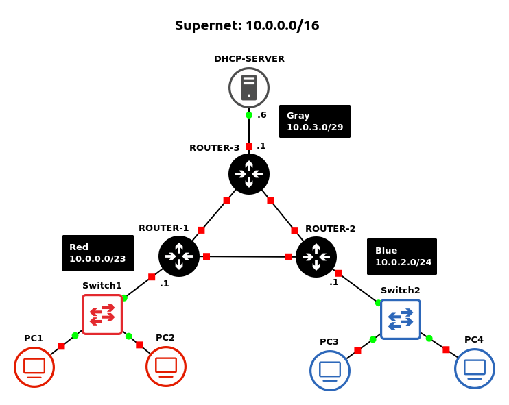
By the end of this lab your network will look like the following:
- Open GNS3
- Open the previous Chapter 26 lab
- Save it as a new project: LAB_13
- Modify the network environment:
- Remove the manually assigned static routes from Router1
> ip route remove 0,1,2,3
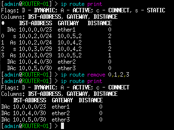
Figure 2 – Removing static routes - Repeat for the other two routers
- Remove the manually assigned static routes from Router1
- Label and organize your network as necessary
Phase II – Configuring RIPv2 on MikroTik RouterOS
- Initialize a Wireshark capture between Router1 and Router2
- Create a new RIPv2 instance on Router1
> routing rip instance add name=RIP-ROUTER-01 redistribute=connected,rip
> routing rip interface-template add interfaces=all instance=RIP-ROUTER-01
- Create a new RIPv2 instance on Router2
> routing rip instance add name=RIP-ROUTER-02 redistribute=connected,rip
> routing rip interface-template add interfaces=all instance=RIP-ROUTER-02
- Focus on the Wireshark capture window
- You should start to see RIPv2 Request and Response messages being exchanged to the IP 224.0.0.9 over port 520
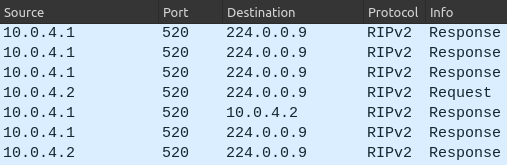
Figure 3 – Wireshark packet capture filtered for RIP - Opening any one of these packets will reveal the routing table being distributed
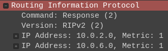
Figure 4 – RIP packet analysis - The recipient routers will use this information to update their own routing tables
> ip route print
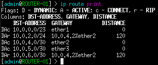
Figure 5 – Updated routing table
- You should start to see RIPv2 Request and Response messages being exchanged to the IP 224.0.0.9 over port 520
- Configure RIPv2 on Router3
- Test the network’s new ability to dynamically update its routes
- Try requesting a new IP address on PC1 and PC3
NOTE: Did you remember to configure Router1 for DHCP-Relay?
- View the route taken from PC1 to PC3
> trace 10.0.2.X -P 1
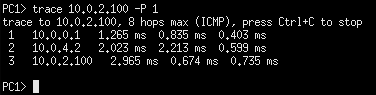
Figure 6 – Tracing path to PC3 - Cut the path that the ICMP packet took to test if RIP can dynamically update network paths
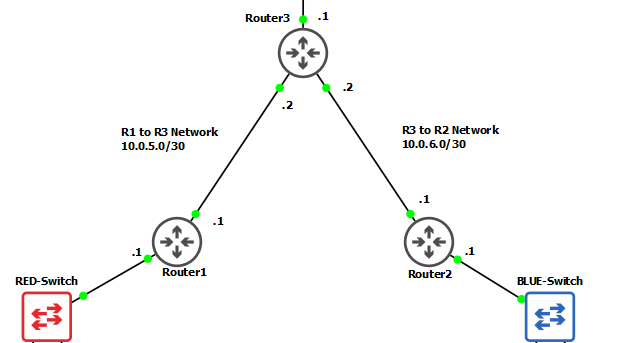
Figure 7 – Cutting path from Router 1 to Router 2 > trace 10.0.2.X -P 1
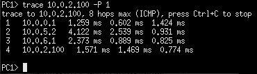
Figure 8 – Tracing route to PC3
- Try requesting a new IP address on PC1 and PC3
Hopefully this exercise proved how significantly easier routing protocols are compared to manually assigning routes in networks.
End of Lab
Deliverables
3 Screenshots are required to consider this lab complete:
- Screenshot of GNS3 workspace (LANS labeled with correct IPs and Subnets)
- Screenshot of DHCP configuration settings
- Screenshot of Wireshark packet showing RIPv2 network advertisement for all networks
Homeworks
Assignment 1 – Update the network build in Assignment 1 from the previous chapter
- Configure DHCP to support the network
- Replace static routes with RIPv2
- RECOMMENDED GRADING CRITERIA
- Screenshot of GNS3 Workspace with all devices labeled
- Screenshot of the DHCP configuration
- Screenshot of RIPv2 packets
- Wireshark Packet Captures where a Green host can ping
- Red Host
- Blue Host
- Gray Host
- Sample network environment:

Figure 9 – Assignment 1 network
Assignment 2 – Update the network build in Assignment 2 from the previous chapter
- Configure DHCP to support the network
- Replace static routes with RIPv2
- RECOMMENDED GRADING CRITERIA
- Screenshot of GNS3 Workspace with all devices labeled
- Trace route command showing that an ICMP packet from a Blue host takes different paths to reach the Purple host (You may have to disconnect some connections to force the change in path)
- Router2 –> Router5
- Router2 –> Router1 -> Router5
- Router2 –> Router3 -> Router1 -> Router5
- Router2 –> Router3 -> Router1 -> Router4 -> Router5
- Sample network environment:

Figure 10 – Assignment 2 network