30 Dynamic Networking – Open Shortest Path First
Mathew J. Heath Van Horn, PhD and Jacob Christensen
Open Shortest Path First (OSPF) is quite complicated to implement, but it makes things very simple for users. Its essence is that routers share information with each other so that when a data packet needs to go from Point A to Point B, all the routers know the fastest path through the network. The “fastest path” can be decided by the physical distance between routers (speed of light energy loss), electrical distance (router hops), and availability and reliability. This means you can’t just look at a network diagram and make assumptions about speed. In this lab, we will build an OSPF network with several paths. We will look at how the OSPF builds a network topology and shares the information amongst the routers. We will also watch how the familiar ICMP packets traverse the network.
Estimated time for completion: 30 minutes
Learning objectives
- Successfully configure an enterprise network to use OSPF routing
- Use Wireshark to identify packets specifically associate with OSPF
- Implement a DHCP Relay solution to an enterprise network
- Use CIDR subnetting techniques to minimize the IP network space waste
Prerequisites
Deliverables
- 5 screenshots are required to receive full credit for this assignment
- GNS3 working environment will have all devices on and labeled correctly
- A router display of all the IP routes – all four router IDs should be visible
- Wireshark showing OSPF Hello Packets
- Wireshark shows ICMP packets between PC1 and PC3 using one path
- Wireshark shows ICMP packets between PC1 and PC3 using a different path
Resources
- MikroTik RouterOS Documentation – OSPF – https://help.mikrotik.com/docs/display/ROS/OSPF
- IBM – Packet Types for OSPF – https://www.ibm.com/docs/en/i/7.1?topic=concepts-packet-types-ospf
Contributors and Testers
- Dante Rocca, Cybersecurity Student, ERAU-Prescott
- Kyle Wheaton, Cybersecurity Student, ERAU-Prescott
Phase I – Terminology
OSPF relies on many terms to describe the relationship between the routers and the routing processes. We will use many of these in this lab, so we will list them here. The list is from the MikroTik RouterOS manual but will be summarized. so you don’t have to flip back and forth between websites.
- Adjacency – A logical connection between a router and a designated router and a backup designated router. No routing information is exchanged unless adjacencies are formed.
- Area Border Router (ABR) – A router that is connected to multiple areas and is responsible for summarizing and update suppression between network areas.
- Autonomous System (AS) – Routers that use a common routing protocol to exchange information.
- Autonomous System Boundary Router (ASBR) – A term used to describe a router that is connected to an external network and imports the external routes into the OSPF topology.
- Back-up Designated Router (BDR) – A hot standby for the designated router and receives all routing updates from adjacent routers, but does not flood with updates.
- Broadcast – Network protocols that allow broadcasting (e.g. Ethernet)
- Cost – Each link in the network is assigned a cost, a value that is dependent upon the speed of the media. Also known as the interface output cost since the time inside a router is not counted.
- Designated Router (DR) – A router unique to broadcast network protocols that are used to minimize the number of adjacencies formed.
- Interface – The router’s physical interface (e.g. ether1). Also known as a link in OSPF parlance.
- Link State – The status of a link between two routers. It defines the relations between a router’s interface and its neighboring routers.
- Link State Advertisement (LSA) – A specialized data packet that contains link-state and routing information and is shared between routers.
- Neighbor – A connected OSPF router with adjacent routers in the same area.
- Non-broadcast multi-access (NBMA) – Routers that allow access, but do not broadcast their information.
- Point-to-Point – A network solution that eliminates the need for DRs and BDRs.
- Router ID – IP address used to identify the OSPF router. Can be manually or automatically assigned.
Phase II – Setup
The purpose of this lab is to set up and configure OSPF. However, to get to that point, some initial configuration is required. If you saved your configuration from Static Routing or RIPv2, you can reuse it. However, you gain more experience and suffer fewer “I forgot to reset XXXX” problems if you start from scratch.
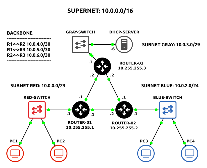
By the end of this lab, your network will look like the following
- Open GNS3
- Open the previous Chapter 27 lab
- Save it as a new project: LAB_14
- Remove RIP from the network environment
- In Router1, remove RIPv2 advertisements from all interfaces
> routing rip interface-template remove 0
- Terminate the RIPv2 instance
> routing rip instance remove 0
- In Router1, remove RIPv2 advertisements from all interfaces
- Assign Router1 a new loopback address to be used as device identifiers for OSPF
- Create a new loopback interface
> interface bridge add name=loopback
Command Meaning interface Access the interface menu directly bridge every ethernet frame received on this point gets transmitted to all other points add create a new interface name= what follows will be a name for this new interface loopback This self-documenting name allows humans to know the purpose of this bridge interface NOTE: Loopback interfaces are useful in that they are always online. They cannot go up and down like a physical interface.
- Assign it a unique IPv4 address – 10.255.255.1
> ip address add address=10.255.255.1/32 interface=loopback
Command Meaning ip address access the ip address menu directly add create a new IP address address= what follows will be the new IP address 10 10 is the start of the backbone IP space 255.255 255 can have several meanings such as “all”, wildcard, no change, etc. In this case, it is a notation saying that this is not a network address for use by the network. 1 this indicates it is router 1 /32 CIDR notation means that only 1 IP address is allowed. It serves as another notation about non-network address interface= what follows is the interface that will use this IP address loopback the interface name. In this case, it is referring to the bridge interface we created earlier NOTE: Loopback addresses can be anything (with some exceptions) as long as they are unique to the device. Since we are using them as device identifiers, it is important to be able to quickly differentiate between a routing IP address and a loopback address. For the purpose of documentation and organization, we are using the format 10.255.255.X for the loopback addresses on this network, where X represents the router’s number (ex 1, 2, and 3). This is not a hard-and-fast rule… feel free to adjust as necessary.
- Create a new loopback interface
- Repeat steps 2 and 3 above on both Router2 and Router3. Remember to change the values for each router.
- Update your network diagram with new router ID labels
Phase III – OSPF
OSPF is a link-state routing protocol that finds the shortest path between two network points and then uses this path to send packets. In our current configuration, there is no “shortest path” per se, we are just looking to get OSPF working so you can see it in action.
OSPF configuration in MikroTik Routers follows a basic format:
- Create a loopback interface
- Enable the OSPF routing protocol
- Configure the OSPF area
- Configure the OSPF network
- Start a Wireshark packet capture on the Router1-Router2 link
- Configure OSPF on Router1
- Create an instance of OSPF and assign the router’s loopback address to serve as the router’s ID
> routing ospf instance add name=Bob version=2 router-id=10.255.255.1
Command Meaning routing ospf instance access the routing ospf instance menu directly add create a new OSPF instance name= what follows is the name we are giving this instance Bob The name, it could be anything that helps humans understand why it is here: marketing, default, building-17, etc. We are using Bob because why not Bob? We are only going to have 1 instance, so it doesn’t matter. version=2 version 2 indicates that we are using OSPF IPv4 networks, version=3 would indicate IPv6 router-id= what follows is the ID number of the router 10.255.255.1 Not a real IP address meaning router 1 on network space 10.0.0.0 - Create the OSPF area by typing
> routing ospf area add name=backbone area-id=0.0.0.0 instance=Bob
Command Meaning routing ospf area access the routing ospf area menu directly add create a new area name= what follows is the name we are giving this area backbone this is our main area area-id= what follows is the ID number for the area name – NOTE: 0.0.0.0 is always the backbone instance=Bob what follows is the instance we are going to use, in this case, we will use the instance ‘Bob’ that we created earlier - Add each interface connected to Router1 to the OSPF backbone area
> routing ospf interface-template add area=backbone interfaces=all
NOTE: There are several additional ways to create the interface template by….
1. Assigning interface names individually
> routing ospf interface-template add area=backbone interfaces=loopback
> routing ospf interface-template add area=backbone interfaces=ether1
2. Assigning specific networks instead of interfaces
> routing ospf interface-template add area=backbone network=x.x.x.x/x
- Create an instance of OSPF and assign the router’s loopback address to serve as the router’s ID
- In Wireshark, you should now see OSPF Hello packets broadcast at a regular interval of every 10 seconds (further dissected in Phase III)
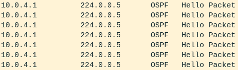
Figure 2 – Wireshark packet capture - Repeat the above steps to configure OSPF for Router2 and Router3
NOTE: Remember, in this example, Router 2’s ID is 10.255.255.2 and Router3’s ID is 10.255.255.3.
- You will know when you are successful if you see the following OSPF packets in Wireshark
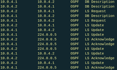
Figure 3 – OSPF routing data exchange - Stop the Router1-Router2 Wireshark packet capture
NOTE: Do not close the window yet! We will come back to this in the next section.
- Wait a minute for OSPF to fully exchange routing tables for the entire network…

Figure Zzzzzz - Test the environment
- Request an IP address to devices in both the red and blue subnets to verify DHCP is operational
- From the PC1 console, trace the route taken to PC3
> trace 10.0.2.100 -P 1
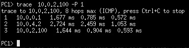
Figure 4 – Tracing connection between PC1 and PC3 - Cut the connection between Router1 and Router2
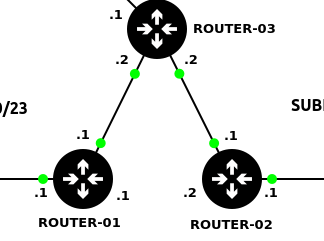
Figure 5 – Cutting Router1-Router2 link - Retrace the PC1-PC3 route to verify it can dynamically update the optimal network path
> trace 10.0.2.100 -P 1
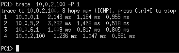
Figure 6 – Tracing connection between PC1 and PC3
OSPF Troubleshooting
The following router commands are useful in troubleshooting errors you might encounter. Below is the expected output for Router1.
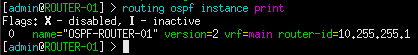
1. All created OSPF instances. In this example, there should only be one per router.
> routing ospf instance print
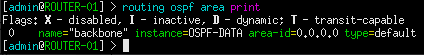
2. All created OSPF areas. In this example, there should only be one backbone area per router.
> routing ospf area print
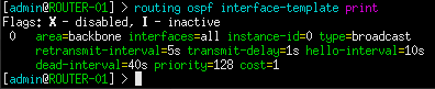
2. Instances set to be configured with OSPF. Your output may vary depending whether you specified individual interfaces or networks.
> routing ospf interface-template print
3. All current OSPF neighbors currently sharing routing information. There should be two neighbors listed: Router2 and Router3. Pay attention to the router-id values to identify which is which.
> routing ospf neighbor print
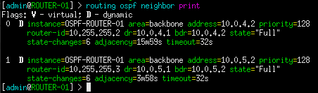
NOTE: If the Router1-Router2 link is still cut, there will only be one neighbor shown until this connection is restored.
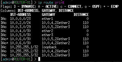
5. All routes currently known by the host router. This should contain every subnet ID on this network.
> ip route print
Phase IV – Dissecting OSPF Traffic
OSPF is a noisy protocol when no constraints are made. You should see many different kinds of packets appearing on the Wireshark capture.
- Focus on the previous Router1-Router2 Wireshark capture
NOTE: You can always generate more OSPF traffic by deleting then restoring any router-adjacent connection.
- Filter only for OSPF packets
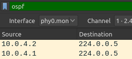
Figure 12 – Filtered Wireshark capture - [Hello Packet]
These packets are sent every 10 seconds (default) out of configured interfaces. The Hello Packets are used to discover OSPF neighbors and help build adjacency. Notice that the destination for the Hello Packets is 224.0.0.5. This is the broadcast address for the OSPF protocol.
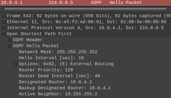
Figure 13 – OSPF Hello - [DB Description]
Database description packets are distributed after the OSPF handshake between two routers has been established. Here, they will advertise the current state of their internal OSPF database. In the example below, Router2 is telling Router1 that it currently has five links to offer: three directly connected and two remote.
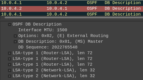
Figure 14 – OSPF database descriptor - [LS Update]
Link state update packets are used exchange network information between OSPF neighbors. This will occur any time routing information is altered, such as a cable being cut, an interface going offline, or the addition of new links. The example below shows Router2 advertising the networks 10.0.2.0/24 and 10.255.255.2/32 to Router1.
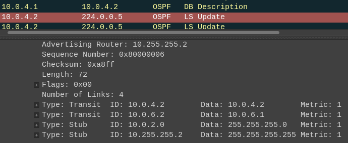
Figure 15 – OSPF link-state update - [LS Request]
After an LS Update is received, the router will transmit a link state update packet for further information about the network. This will then be followed by additional LS Update packets contain the requested data.
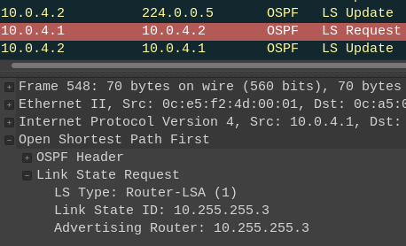
Figure 16 – OSPF link-state request - [LS Acknowledge]
An acknowledgment of given after every LS Update is received.
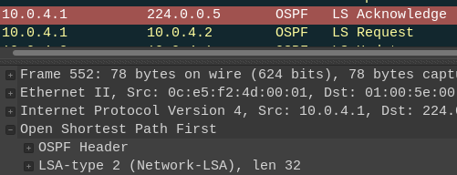
Figure 17 – OSPF link-state acknowledgement
- Filter only for OSPF packets
End of Lab
Deliverables
5 screenshots are required to receive full credit for this assignment
- GNS3 working environment will have all devices on and labeled correctly
- A router display of all the IP routes – all four router IDs should be visible
- Wireshark showing OSPF Hello Packets
- Wireshark shows ICMP packets between PC1 and PC3 using one path
- Wireshark shows ICMP packets between PC1 and PC3 using a different path
Homeworks
Assignment 1 – Update the network build in Assignment 1 from the previous chapter
- Configure DHCP to support the network
- Replace RIPv2 routing with OSPF
- RECOMMENDED GRADING CRITERIA
- Screenshot of GNS3 Workspace with all devices labeled including Router IDs
- Screenshot of the DHCP configuration
- Screenshot of OSPF packets
- Wireshark Packet Captures where a Green host can ping
- Red Host
- Blue Host
- Gray Host
- Sample network environment:

Figure 18 – Assignment 1 network
Assignment 2 – Update the network build in Assignment 2 from the previous chapter
- Configure DHCP to support the network
- Replace RIPv2 routing with OSPF
- RECOMMENDED GRADING CRITERIA
- Screenshot of GNS3 Workspace with all devices labeled including Router IDs
- Trace route command showing that an ICMP packet from a Blue host takes different paths to reach the Purple host (You may have to disconnect some connections to force the change in path)
- Router2 –> Router5
- Router2 –> Router1 -> Router5
- Router2 –> Router3 -> Router1 -> Router5
- Router2 –> Router3 -> Router1 -> Router4 -> Router5
- Sample network environment:

Figure 19 – Assignment 2 network
Assignment 3 – Preparation for BGP lab
- Create the following OSPF full-mesh network
- This will be used in the setup for the next chapter – Border Gateway Protocol Networking
- Network environment
< insert image >