42 Network Hardening – OSPF Encrypted Authentication
Jacob Christensen; Arjun Nath; and Isha Patel
In a previous chapter, learners built, configured, and implemented a network that is dynamically routed OSPF into their networks via MikroTik routers. This allowed routers to find the shortest path from Point A to Point B and send information through that path. However, OSPF by default has no forms of authentication. An attacker with a malicious router running OSPF could disrupt and manipulate network and routing information. OSPF packets are easily viewable in plaintext and can contain information that could help an attacker exploit a network.
In this chapter, we will implement router-to-router encrypted authentication to ensure valid router identity before updating networking tables. This will help secure OSPF and prevent unauthorized modification of routes, redirection of traffic, and unauthorized exploitation of network information.
Learning Objectives
- Learn how to securely authenticate OSPF traffic
Prerequisites
Deliverables
- Screenshot of GNS3 environment
- Screenshot of OSPF interface-templates showing authentication
- Screenshot of trace command showing rouge router has been thwarted
Resources
Contributors
- Dante Rocca, Cybersecurity student, ERAU-Prescott
- Jungsoo Noh, Cybersecurity Student, ERAU-Prescott
Phase I – Building the Network Topology
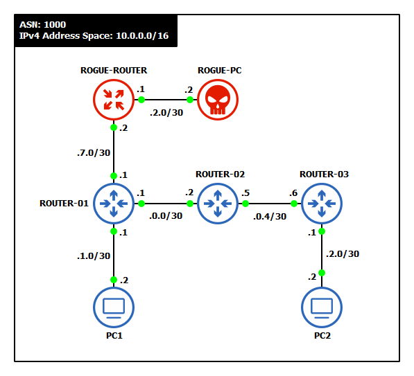
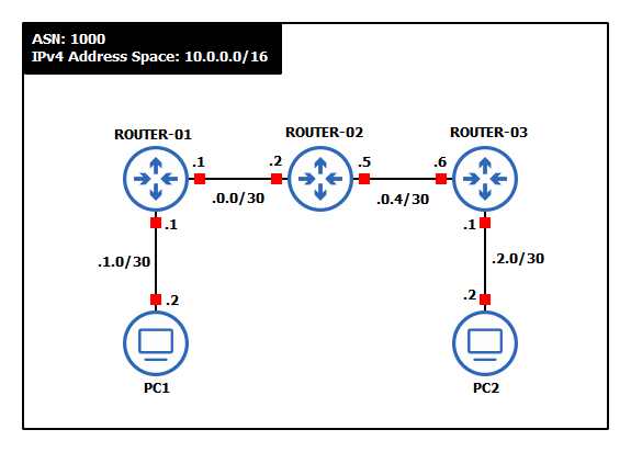
This lab is an extension of the OSPF Networking chapter. If you have not completed it yet, it is recommended that you do so first before continuing. By the end, your network should resemble the following topology:
- Start GNS3
- Create a new project and name it
- Build one OSPF-networked Autonomous System with the following specifications:
- Use a randomly generated IPv4 network address space with a 16-bit CIDR mask
NOTE: This example uses 10.0.0.0/16 for its supernet IP space and /30 for device-to-device subnets.
- Three routers – MikroTik CHR
- Two client machines – VPCS or TinyCore Linux
- Use a randomly generated IPv4 network address space with a 16-bit CIDR mask
- Assign static IP addresses to the clients and router interfaces. We used the following
Device Interface Network IPv4 Address ROUTER-01 loopback 10.255.255.1/32 10.255.255.1 ether1 -> PC1 10.0.1.0/30 10.0.1.1 ether2 -> ROUTER-02 10.0.0.0/30 10.0.0.1 ROUTER-02 loopback 10.255.255.2/32 10.255.255.2 ether2 -> ROUTER-01 10.0.0.0/30 10.0.0.2 ether3 -> ROUTER-03 10.0.0.4/30 10.0.0.5 ROUTER-03 loopback 10.255.255.3/32 10.255.255.3 ether1 -> PC2 10.0.2.0/30 10.0.2.1 ether3 -> ROUTER-02 10.0.0.4/30 10.0.0.6 PC1 e0 -> ROUTER-01 10.0.1.0/30 10.0.1.2 PC2 e0 -> ROUTER-03 10.0.2.0/30 10.0.2.2 - Configure OSPF to dynamically exchange network information
- Create a new OSPF instance
> routing ospf instance add name=<instance_name> version=2 router-id=<loopback_IP>
- Create a new backbone area
> routing ospf area add name=backbone area-id=0.0.0.0 instance=<instance_name>
- Add all interfaces to the backbone
> routing ospf interface-template add area=backbone interface=all
- In Wireshark, you should see OSPF Hello, Description, Request, Update and Acknowledgement packets
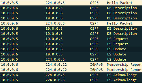
Figure 2 – OSPF output in Wireshark - PC1 should be able to ping PC2

Figure 3 – PC1 pinging PC2 - We can also see the path that it taken to PC2 with the VPCS trace command
> trace 10.0.2.2 -P 1

Figure 4 – Tracing the route to PC2 NOTE: Notice how the output from trace shows that the route to PC2 is three routers (three “hops”) away, as expected.
- Create a new OSPF instance
- Label and organize your network as necessary
Phase II – Rogue Router Network Poisoning
OSPF is a routing protocol that is prone to insecurity due to its constant search for the shortest open path. Think of it as a navigation app telling you to walk through a shady alley to cut a few minutes off your route. Let’s set up a rogue router and PC to help demonstrate this.
- Add two rogue devices to the network
- One router – MikroTik CHR
- One client – VPCS or TinyCore Linux
- Assign/update static IP addresses to the clients and router interfaces
Device Interface Network IPv4 Address ROGUE-ROUTER loopback 99.99.99.99/32 99.99.99.99 ether1 -> ROUTER-01 10.0.7.0/30 10.0.7.2 ether2 -> ROGUE-PC 10.0.2.0/30 10.0.2.1 ROGUE-PC e0 -> ROGUE-ROUTER 10.0.2.0/30 10.0.2.2 ROUTER-01 ether3 -> ROGUE-ROUTER 10.0.7.0/30 10.0.7.1 NOTE: Notice that ROGUE-PC is on the same subnet and assigned the same IP address as PC2.
- Label and organize the new network as necessary
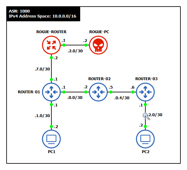
Figure 6 – New network topology - Start a Wireshark capture between ROUTER-01 and ROGUE-ROTUER and see how 10.0.7.1 is already broadcasting OSPF neighbor requests

Figure 7 – OSPF Hello - Create a new OSPF instance on the attacker’s router to advertise the rogue PC’s subnet
- From PC1, execute the trace command again to PC2

Figure 8 – Tracing network route to PC2 NOTE: It appears that OSPF automatically updated the “optimal” route to the 10.0.2.0/30 subnet to redirect it through ROGUE-ROUTER. The attacker has successfully manipulated the network to route all traffic destined for PC2 to themselves.
Phase III – Enabling OSPF Authentication
Notice how each router immediately starts exchanging its routing tables when they are connected to another OSPF session. While this is very convenient when building a network, an attacker could exploit this to their advantage. If a rogue/malicious router were to enter the network with OSPF configured, it could inject false routing information, disrupt, or redirect traffic. For this reason, it is vital to authenticate new routers on the network before accepting routing updates from them.
- Remove the cable connecting the rogue devices to the network
- Start a Wireshark capture between ROUTER-01 and ROUTER-02
- On ROUTER-01, print the interfaces that are currently configured with OSPF
> routing ospf interface-template print

Figure 9 – Printing OSPF interfaces - Enable router-to-router authentication
- Add an authentication key (password) to the first entry in the list
> routing ospf interface-template edit 0
- Type auth-key for the value name

Figure 10 – Edit authentication - In the redirected text editor, type any secure password of your choice
- Press Ctrl + o at the same time to save and close the editor
- Add an authentication key (password) to the first entry in the list
- Secure the password as a cryptographic hash (SHA-256)
- Edit the first entry again
> routing ospf interface-template edit 0
- Type auth for the value name

Figure 11 – Edit authentication - In the text editor, replace simple with sha256
- Press Ctrl + o at the same time to save and close the editor
- Edit the first entry again
- Reprint the interfaces and notice the change to entry zero

Figure 12 – Updated OSPF interfaces - Analyze the network traffic
- In Wireshark, select any OSPF Hello packet with a source IP from ROUTER-01
- Expand the OSPF Header section in packet details
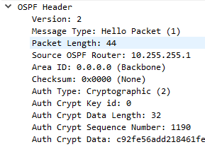
Figure 13 – OSPF packet details NOTE: Now the router will not exchange network information with other routers that do not supply the correct pre-shared key (PSK).
- Repeat steps 1 through 6 with ROUTER-02 and ROUTER-03
- Once two neighbors share the same PSK, you should start to see OSPF exchanges again
Phase IV – Testing Against Rogue Attackers
After all that authentication configuration setup, let’s go ahead and test our network to see if it was successful. If so, we should see that any attempts to route packets outside of our configured network to any rogue points should fail.
- Reconnect the rogue router to ROUTER-01
- Wait a minute for all OSPF to successfully exchange/update routes

Figure 14 – Waiting waiting waiting… - From PC1, execute the trace command to PC2

Figure 15 – Tracing the network path to PC2 NOTE: Despite ROGUE-PC having the “shortest path” (least number of hops), PC1 can network to PC2! With our new authentication in place, OSPF did not update any routing tables with false information this time. This is just one layer of defense when it comes to network security.
End of Lab
Deliverables
Three screenshots are necessary to earn credit for this exercise
- Screenshot of GNS3 environment
- Screenshot of OSPF interface templates showing authentication
- Screenshot of trace command showing rouge router has been thwarted
Homeworks
Assignment 1: Rebuild the OSPF network from chapter 30 with authentication
- Use the same topology from the chapter
- Add authentication to the network
Assignment 2: Business expands
- Add a Green subnet
- Add a rogue subnet that imitates the Green subnet
- Show that the rogue subnet does not affect the network, thanks to authentication
RECOMMENDED GRADING CRITERIA: Same as the deliverables


