39 Network Hardening – Network Segmentation and Isolation
Mathew J. Heath Van Horn, PhD
Many networks are worried about exterior facing security holes. The network interior is largely overlooked as needing security management. However, many advanced persistent threat actors use the application layer to gain access to the interior network and then pivot to other internal network targets. e.g. an APT gains access to the web server, where they can cause mischief, but without inside the network security, that web server access could give way to the research, employee, and accounting servers.
To prevent this, we can create obstacles to slow the threat actor down long enough to counter their attacks. Think how hedgerows in WW II Europe slowed the Allied advance on Germany (Hedgerow History1) (HedgerowHistory2). In an enterprise network, the cybersecurity person’s hedgerows used against threat actors are virtual local area networks (VLANs) and they enhance network security through network segmentation and isolation.
LEARNING OBJECTIVES
- Adding a switch to a network environment
- Segment a homogenous network into several isolated networks
- Use DHCP to test network connectivity
- Develop a firewall filter to complete network segmentation
PREREQUISITES
Deliverables
- Wireshark packets from PC 1 showing successful pings to PC 5 and PC 3
- Screenshot of VLAN table for Switch 1
- Screenshot of VLAN table for Switch 2
- Screenshot of PC5 unable to ping 99.99.99.1 and 99.99.99.2
Resources
- MikroTik Documentation – Bridging and Switching – https://help.mikrotik.com/docs/display/ROS/Bridging+and+Switching#BridgingandSwitching-BridgeHardwareOffloading
- Wilmer Almazan / The Network Trip – “Mikrotik VLANs – CRS3XX Step by Step – Mikrotik Tutorial” – https://www.youtube.com/watch?v=YLtGQAQ8iS0
Contributors and Testers
- Sarah Davis, Cybersecurity Student, ERAU-Prescott
- Calvin Lindemann, Cybersecurity Student, ERAU-Prescott
- Eliana Seitz, Cybersecurity Student, ERAU-Prescott
- Morgan Finch, Cybersecurity Student, ERAU-Prescott
- Tyler Jane McClure, Cybersecurity Student, ERAU-Prescott
Phase I – Setup
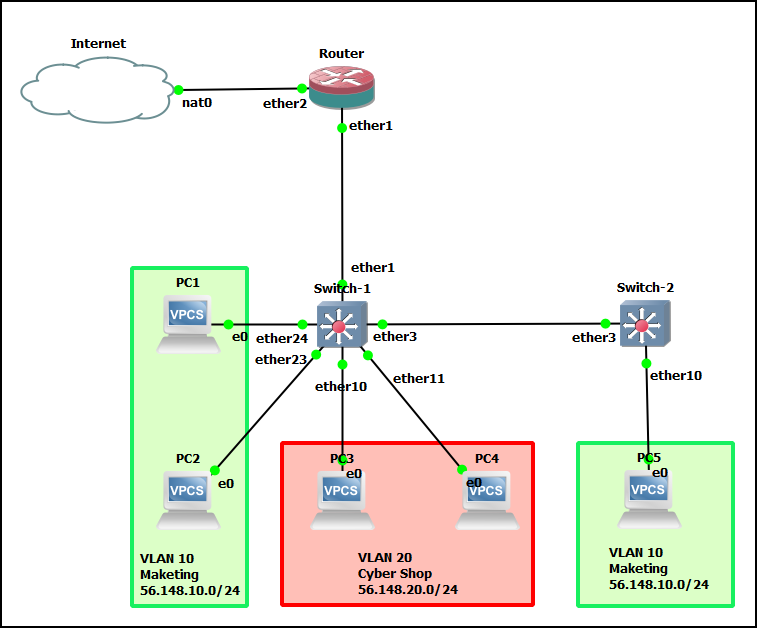
In this lab, you will build the following GNS3 network…
Phase II – Adding a Switch to GNS3
MikroTik’s RouterOS operating system works the same for both switches and routers. Their physical switches have an extra circuit that allows for OSI Layer 2 switching functions. This means that if were to configure a MikroTik router as a switch in GNS3, it wouldn’t work because the extra circuit isn’t present. However, we can approximate the same settings. Others have struggled with this problem and have taken the MikroTik router image and modified it to support switching.
- Start GNS3 so it can boot while we download the appliance
- Create a new project
- In GNS3, navigate to File–>New Template
- Select Install an appliance from the GNS3 server and click Next
- Under Switches, select MikroTik CRS328-24P-4S+ and click Install
NOTE: This is a multi-layer switch, but we are going to treat it as a Layer 2.
- Select Install the appliance on the GNS3 VM and click Next
- Leave the Qemu settings as their default and click Next
- Highlight the latest image (.img) version and click Download
NOTE: GNS3 will remind you to unzip the downloaded sub-image. You need to do this before you can import it.
- Again, highlight the image version you just downloaded and click Import
- Select the image file and click Open
- Highlight the appliance you want to install and click on Next
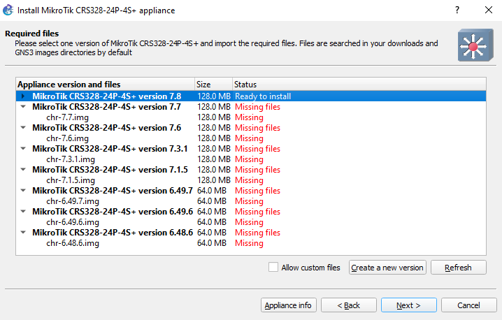
Figure 2 – Ready to install - Select Yes on the popup window
- Read about how the image is to be used and click Finish
- In GNS3, navigate to either the switch icon or the all devices icon, and you can see the MikroTik CRS328 switch has been added
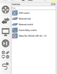
Figure 3 – Completed Installation
Phase III – Preconfiguring the Switch
There isn’t much to do in this phase. However, because we are using a MikroTik cloud router as a multi-layer switch and restricting it to only using OSI Layer 2, a few tweaks need to be made.
- Drag the MikroTik switch to the design area
- Start the MikroTik switch and open its console
- This has the same first boot steps as the MikroTik router
- Login: admin
- Password: <blank, just hit enter>
- Select n when asked to see the software license
- When asked for a new password choose something you will remember, in this book we typically use Security1
- Change the switch name by typing (where <new name> means your chosen name for the device)
> system identity set name=<new_name>
- Create two switches in this way.
Phase IV – Create the bridge
A bridge is a device responsible for dividing a network into various segments. These segments might be geographical (house, garage, workshop) or functional (marketing, accounting, printers). This segmentation creates network domains so that if a packet collision occurs, the collision will not affect the rest of the network. The bandwidth assigned to the bridge can be adjusted to reduce the number of packet collisions. This also helps if a threat actor is deliberately trying to cause collisions on our network in DoS or DDoS attack type. It won’t stop the attack, but it will prevent it from affecting more than one part of the network.
A bridge device is software-controlled, which allows many switches to be configured to act as bridges. Bridges forward packets with no error checking and generally have no buffer for unsent packets like switches often do.
- The hardware platforms for MikroTik switches generally have more than one bridge, but because our emulated hardware doesn’t have the switch chips, we can only use one, which makes things easy to set up, but it might look goofy since we use the name “bridge1” frequently.
- To create the bridge type
> interface bridge add name=bridge1
- Create the same bridge for Switch 2. For the bridge use the name ‘bridge1’ as well
Phase V – Plan the Network
In the opening figure, you can see we want to design a network separated into three functional areas. We will build a very simple LAN containing three VLANs:
- VLAN 10: 56.148.10.0/24 Marketing
- VLAN 20: 56.148.20.0/24 Cyber
- VLAN 99: 99.99.99.0/24 Management
Remember: Switches are Layer 2, they do not recognize IP headers (Layer 3). Therefore, we need a router to facilitate communications between the VLANs.
Furthermore, there are some specialty terms we need to be familiar with:
- Tagged – This means the interface handles traffic from more than one source (Trunked)
- Untagged – This means the interface handles traffic for only one source (Access Point)
- PVID – Port VLAN ID for access ports to tag all ingress traffic with a VLAN ID
These tags are used by the bridge filters to direct the packets to the appropriate VLAN without having to deconstruct the packet header which saves a lot of time. We don’t tag trunked traffic because there could be many different tagged packets in this path.
- Add all the devices shown in the first diagram. Connect the cables. Feel free to use any interfaces you desire, but we used the following:
Device Interface Destination Router ether1 switch1 – ether1 ether2 Internet Switch 1 ether1 router – ether1 ether3 switch2 – ether3 ether24 PC1 ether23 PC2 ether10 PC3 ether11 PC4 Switch 2 ether3 switch1 – ether3 ether10 PC5 - Identify the VLANs, PVID, Tagged, and Untagged interfaces. Remember, tagged interfaces are trunks (multiple endpoints), and untagged interfaces are access points (single endpoint)
VLAN PVID Switch 1
TaggedSwitch 1 Untagged Switch 2
TaggedSwitch 2 Untagged VLAN 10 PVID10 ether1 ether23 ether3 ether10 ether3 ether24 VLAN 20 PVID20 ether1 ether10 ether11 VLAN 99 PVID99 ether1 ether3 bridge bridge
Phase VI – Implement the network
Once you have worked out your network with pencil and paper, it makes implementation MUCH easier. I know you won’t believe me, but when you take 4-5 hours to set up your devices and I take 30 minutes, maybe you’ll learn this life lesson. Anyway, take your pencil-paper plan and implement it on your equipment step by step.
- Start all devices
- Configure the router
- Open the router console and add the VLANs by typing
> interface vlan add name=VLAN10 vlan-id=10 interface=ether1 disabled=no
> interface vlan add name=VLAN20 vlan-id=20 interface=ether1 disabled=no
> interface vlan add name=VLAN99 vlan-id=99 interface=ether1 disabled=no
NOTE: It seems like we reuse labels and names a lot. However, when learning network segmentation, it is better to be repetitive instead of using trendy names and numbers because there is less chance of fat-fingering or misremembering something:
> interface vlan add name=death-star vlan-id=826 interface=ether1 disabled=no
- Add an IP address to each of the VLANs by typing
> ip address add address=56.148.10.1/24 interface=VLAN10
> ip address add address=56.148.20.1/24 interface=VLAN20
> ip address add address=99.99.99.1/24 interface=VLAN99
- Open the router console and add the VLANs by typing
- Add ports to the bridge
- Configure Switch-1 – Add ports by typing
> interface bridge port add bridge=bridge1 interface=ether1
> interface bridge port add bridge=bridge1 interface=ether3
> interface bridge port add bridge=bridge1 interface=ether23 pvid=10
> interface bridge port add bridge=bridge1 interface=ether24 pvid=10
> interface bridge port add bridge=bridge1 interface=ether10 pvid=20
> interface bridge port add bridge=bridge1 interface=ether11 pvid=20
NOTE: Remember, on Switch-1:
– ether1 and ether3 are trunk ports – no tags at this time (e.g. pvid), or we will lose packet traffic
– ether23 and ether24 are part of VLAN 10 – Marketing – so as a mental reminder they are part of VLAN 10, we use a pvid of 10
– ether10 and ether11 are part of VLAN 20 – Cyber Shop – so as a mental reminder, they are part of VLAN 20, we use a pvid of 20 - Configure Switch-2
- Create the bridge
> interface bridge add name=bridge1
- Assign the interfaces to the bridge
> interface bridge port add bridge=bridge1 interface=ether3
> interface bridge port add bridge=bridge1 interface=ether10 pvid=10
- Create the bridge
- Configure Switch-1 – Add ports by typing
- Create the VLAN tables
- Configure Switch-1
> interface bridge vlan add bridge=bridge1 tagged=ether1,ether3 untagged=ether23,ether24 vlan-ids=10
> interface bridge vlan add bridge=bridge1 tagged=ether1,ether3 untagged=ether10,ether11 vlan-ids=20
- Create the VLAN table in Switch2 by opening the console and typing
> interface bridge vlan add bridge=bridge1 tagged=ether3 untagged=ether10 vlan-ids=10
- Configure Switch-1
- Set VLAN filtering to both switches by typing in each console
> interface bridge set bridge1 vlan-filtering=yes
- Check your VLAN table on Switch-1 by typing
> interface bridge vlan print
- Take a screenshot of the VLAN table for both Switch-1 and Switch-2
Phase VII – Management LAN
Management of Enterprise Infrastructure is not as easy as GNS3 makes it look. Most of the time, you will never have the ability to plug in a monitor, keyboard, and mouse into a network device. Therefore you need a means to access the device settings. So for us to remote into these devices in the future, we are going to create a management network.
Normally, we would need to assign an IP address to each port. But since bridges listen on every port, we are going to take advantage of this by doing the following:
- Create a VLAN bridge, assign all trunks to it (ether1, ether3, and bridge1), and tag all management packets with a VLAN ID of 99. (Segmentation is the name of the game. Threat agents can attack management LANs as well!)
- Add an interface to the vlan, using the existing bridge1 interface, name it, then declare which tagged packets will use it.
- Finally, assign an IP address just like any physical interface.
- Create the Management VLAN
- Configure Switch-1 by typing
> interface bridge vlan add bridge=bridge1 tagged=bridge1,ether1,ether3 vlan-ids=99
> interface vlan add interface=bridge1 name=VLAN99 vlan-id=99
> ip address add address=99.99.99.2/24 interface=VLAN99
- Configure Switch-2 by typing
> interface bridge vlan add bridge=bridge1 tagged=bridge1,ether3 vlan-ids=99
> interface vlan add interface=bridge1 name=VLAN99 vlan-id=99
> ip address add address=99.99.99.3/24 interface=VLAN99
- Configure Switch-1 by typing
- Test connectivity on the management LAN by pinging the Router (99.99.99.1) and Switch-1 (99.99.99.2) from Switch-2 (99.99.99.3)
Phase VIII – Testing the whole thing with DHCP
To test the whole environment without having to pass a lot of notional packets, we can use DHCP to verify connectivity. MicroTik routers have the capability of acting like a DHCP server and are RFC 2131 compliant. For this example, we will use the following DHCP Settings:
| Interface | Address | Pool |
| VLAN10 | 56.148.10.1/24 | 56.148.10.10 – 56.148.10.250 |
| VLAN20 | 56.148.20.1/24 | 56.148.20.10 – 56.148.20.250 |
Notes:
- The server’s IP must not be within the pool!
- The server will not look to deconflict with devices having static IP addresses. You’re smarter than the machine, don’t cross the IP streams!
- Navigate to the router. Remember, we already set the static IP address for VLAN99 on the router at the beginning of this lab to 99.99.99.1/24
- Type the following and answer the questions accordingly
> ip dhcp-server setup
- dhcp server interface: VLAN10
- dhcp address space: 56.148.10.0/24 (should be filled out, just hit enter)
- gateway for DHCP network: 56.148.10.1 (should be filled out, just hit enter)
- addresses to give out: 56.148.10.10-56-148.10.250 (change the default)
- dns servers: 8.8.8.8,8.8.4.4 (no spaces)
- lease time: 1800 (should be filled out, just hit enter)
- Repeat Step 2 for VLAN20 with the VLAN20 details
- Open the consoles on the respective VPCS and get a DHCP IP by typing
> ip dhcp
- Note the IP address assigned. PCs on VLAN 10 should get IP addresses from the 56.148.10.0/24 pool and PCs on VLAN 20 should get IP addresses from the 56.148.20.0/24 pool
- Open a Wireshark packet capture and from PC1, ping PC5 and PC3 and screenshot the successful results
- Now from PC 5, ping 99.99.99.1 and notice that it is successful. From PC3 Ping 99.99.99.1 and notice that it is successful. This behavior is not desirable. Remember, our 99.99.99.0 network is our control network, users should not have access to it
Phase IX – Setting up router firewall
Marketing users and Cyber Shop users should not have access to the network management LAN. We need to stop this access by applying firewall rules on our router.
- Navigate to the router console and type
> ip firewall address-list add address=56.148.10.0/24 list=users
> ip firewall address-list add address=56.148.20.0/24 list=users
> ip firewall address-list add address=99.99.99.0/24 list=management
- Now type
> ip firewall filter add action=drop chain=forward dst-address-list=management src-address-list=users
- From PC5 try to ping 99.99.99.2 and it should not work. But when you ping 99.99.99.1 it does work. That is because when we ping 99.99.99.2 our packets are flagged as ‘forwarding’ packets
- Return to the router and type
> ip firewall filter add action=drop chain=input dst-address-list=management src-address-list=users
- Return to PC5 and try to ping 99.99.99.1 and it should timeout
End of Lab
Deliverables
Four screenshots required
- Wireshark packets from PC 1 showing successful pings to PC 5 and PC 3
- Screenshot of VLAN table for Switch 1
- Screenshot of VLAN table for Switch 2
- Screenshot of PC5 unable to ping 99.99.99.1 and 99.99.99.2
Homeworks
Assignment 1 – Add Switch 3 and connect it to Switch 2. Add two PCs, one from VLAN 10 and one from VLAN 20.
Assignment 2 – Add Switch 4 and connect to Switch 2. Add three PCs, two from VLAN 50 (accounting) and one from VLAN 20.
Recommended Grading Criteria
- Screenshot of Wireshark showing the DHCP addition of the new PCs
- Screenshot of one of the new PCs successfully pinging PC1
- Screenshot of one of the new PCs unable to ping the management VLAN
