24 Dynamic Host Configuration Protocol – MikroTik DHCP Relay
Mathew J. Heath Van Horn, PhD; Jacob Christensen; and Kyle Wheaton
Typically, larger networks are segmented into smaller LANs. However, one concern that can arise from this is the issue of distributing IP addresses across individual subnets. This is because DHCP discover packets are designed to be broadcasted within local networks. While a network administrator could configure a dedicated DHCP server for each LAN, we demonstrated in Static Networking Part 1 that this can quickly become tedious to configure and maintain. Luckily, DHCP relays can be configured to re-transmit IP requests to remote servers. This way, one server can lease addresses to multiple networks at once. In this chapter, we will configure a DHCP relay with a MikroTik router to service two networks.
Estimated time for completion: 60 minutes
Learning Objectives
- Create three functional LANs
- RED – PCs
- BLUE – PCs
- GRAY – DHCP Server
- Configure a router to serve as a functional DHCP relay
- Configure a DHCP server successfully
Prerequisites
Deliverables
- Screenshot of GNS Workspace with labels
- Screenshot of Wireshark DHCP
- LAN1 end devices requesting and receiving IP addresses
- LAN2 end devices requesting and receiving IP addresses
Resources
- MikroTik RouterOS Documentation – DHCP Relay – https://wiki.mikrotik.com/wiki/Manual:IP/DHCP_Relay
- Internet Systems Consortium – The DHCPv4 Server – https://kea.readthedocs.io/en/kea-2.6.2/arm/dhcp4-srv.html#the-dhcpv4-server
Contributors and Testers
- Dante A. Rocca, Cybersecurity Student, ERAU-Prescott
- Kyle Wheaton, Cybersecurity Student, ERAU-Prescott
Phase I -Build the Network Topology
The following steps are to create a baseline environment for completing the lab. It makes assumptions about learner knowledge from completing previous labs.
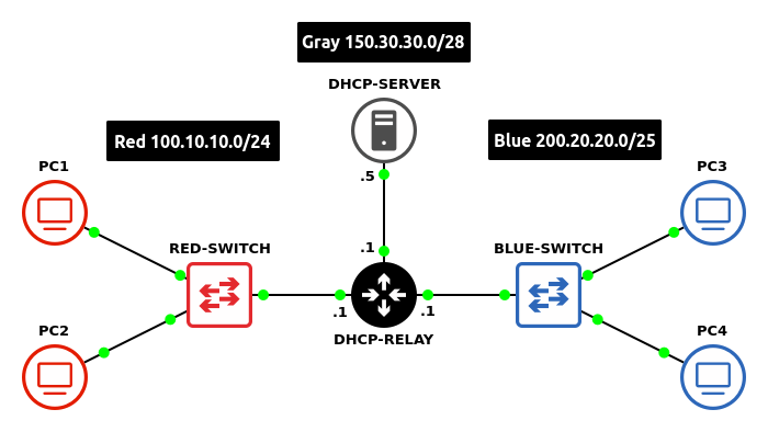
By the end of this lab your network should look like the following:
- Start GNS3
- Create a new project: LAB_08
- Build a small network will the following specifications:
- Subnet – Red
- One switch – Ethernet switch
- Two client machines – VPCS
- Minimize wasted address space for 250 hosts
Network Information Network 100.10.10.0 Netmask 255.255.255.0 (/24) Broadcast 100.10.10.255 Gateway 100.10.10.1 DHCP Lower Bound 100.10.10.2 DHCP Upper Bound 100.10.10.254
- Subnet – Blue
- One switch – Ethernet switch
- Two client machines – VPCS
- Minimize wasted address space for 100 hosts
Network Information Network 200.20.20.0 Netmask 255.255.255.128 (/25) Broadcast 200.20.20.127 Gateway 200.20.20.1 DHCP Lower Bound 200.20.20.2 DHCP Upper Bound 200.20.20.126
- Subnet – Gray
- One DHCP server – Ubuntu Server / Windows Server / Tiny Core / MikroTik CHR
NOTE: This example will use 150.30.30.5 as the server’s static IP address.
- Minimize wasted address space for 10 hosts
Network Information Network 150.30.30.0 Netmask 255.255.255.240 (/28) Broadcast 150.30.30.15 Gateway 150.30.30.1
- One DHCP server – Ubuntu Server / Windows Server / Tiny Core / MikroTik CHR
- Subnet – Red
- Add a MikroTik router to the workspace
- Connect all three networks to the router
- Configure the router with static IP addresses on all active interfaces (Chapter 18, Phase II, Step 4)
NOTE: This example uses the following router ports:
– ether1 -> Red LAN
– ether2 -> Blue LAN
– ether3 -> Gray LAN
- Label and organize your network as necessary

Figure 2 – Final network topology
Since the server is not in the same network as our clients, the router needs to serve as a relay point for the “DHCP Discover” packets.
- Setup the relay
- Open the MikroTik console
- Configure the Red subnet’s relay path
> ip dhcp-relay add name=Red-Relay interface=ether1 dhcp-server=150.30.30.5 local-address=100.10.10.1 disabled=no
Command Description ip dhcp-relay Access the DHCP relay menu. add name=Red-Relay Name this group of configuration settings “Red-Relay”. interface=ether1 Assign the ether1 interface to listen for DHCP requests. dhcp-server=150.30.30.5 DHCP request packets will forwarded to 150.30.30.5. local-address=100.10.10.1 DHCP response packets will arrive with the address 100.10.10.1. disabled=no The default setting is to disable configurations unless otherwise specified. - Configure the Blue subnet’s relay path
> ip dhcp-relay add name=Blue-Relay interface=ether2 dhcp-server=150.30.30.5 local-address=200.20.20.1 disabled=no
NOTE: Don’t forget to disable the DHCP client that is listening by default on ether1!
> ip dhcp-client remove 0
- Verify that the router’s settings are configured properly

Figure 3 – Ensuring router is configured properly > ip address print
> ip dhcp-relay print
Phase III – Configure the Linux DHCP Server
We are going to configure our DHCP server in a similar fashion as we’ve done in previous labs.
Backing up your files…
ALWAYS MAKE A BACKUP! In the following section and the chapters going forward, rewriting configuration files will be commonplace. Whether or not you are someone who makes mistakes, it is always good practice to make backup copies of everything you change. When something goes wrong (and it will), you will be thankful for having these.
Create a backup folder in your home directory:
> mkdir ~/backups
Verify the directory was created:
> ls ~ | grep backups
Copy an existing file to the directory:
> cp /path/to/file/example.txt ~/backups
Verify the backup was made:
> ls ~/backups
If you ever need to restore your backup:
> cp ~/backups/example.txt /path/to/file
- Start the Ubuntu Server VM
- Configure the server to have a static host address

Figure 4 – /etc/netplan/*.yaml file > sudo vi /etc/netplan/50-cloud-init.yaml
> sudo netplan apply
NOTE: Ensure that the server’s IP is NOT the same address as its gateway and is WITHIN the range of available hosts for your subnet! Also, notice that the configuration provided includes the addition of a default gateway. This is important for the server to know how to respond to DHCP request packets. Check if you have a default route set in your server:
> ip route
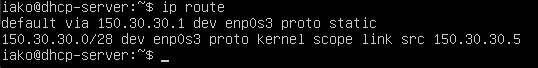
Figure 5 – Server default gateway The above image illustrates that the enp0s3 interface is assigned the address 150.30.30.5 on the 150.30.30.0/24 network with a gateway address pointing towards 150.30.30.1.
- Modify the DHCP daemon configuration file to support all three subnets
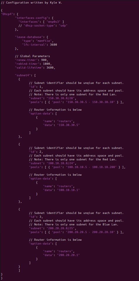
Figure 6 – Configuration of the DCHP service using KEA > sudo vi /etc/kea/kea-dhcp4.conf
NOTE: Declare the Gray subnet. Although there are no clients to service here, it is good practice to help the server understand the layout of our network.
- Ensure that the daemon is enabled and active
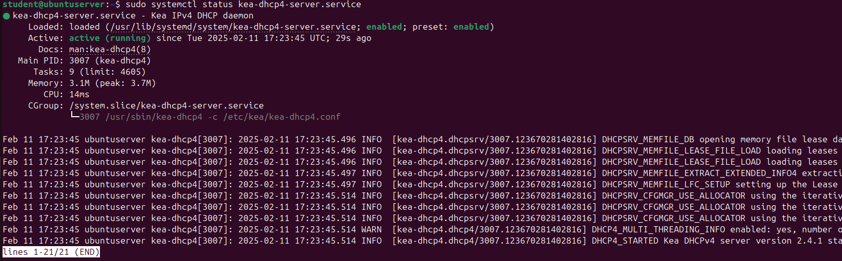
Figure 7 – KEA server status
Phase IV – Connect Devices
With the router configured and the DHCP server running, all that is left is to connect devices to see if everything works.
- Start capturing packets on the PC1-Relay connection
- In PC1’s terminal, request a new IP address
NOTE: If using a Tiny Core VM, it should automatically request an IP address at startup.
- Look for the DHCP broadcast packets on Wireshark (you should see the same packets from when you completed the DHCP labs)
- You can check the VPCS’s assigned IP address in its console
> show ip
- If you want to see more traffic, just add more end devices or renew current leases
- In PC1’s terminal, request a new IP address
- Repeat for the Blue clients
- Ensure that all three subnets can ping each other and have full connectivity
There are many moving pieces in this lab and future labs. You might have to do some troubleshooting. Here are some tips offered by our testers.
RTFQ (Read the “Full” Question): This trips up a lot of people. There are many devices, many IP addresses, many different commands. Whether it be configuring Windows, Linux, or GNS3, it is easy to slip up. Read slowly and the lab will work.
SERVER TROUBLESHOOTING: Testers have found that simply restarting the service resolved many of the common errors you many encounter.
> systemctl restart example.service
However, if a problem persists, you can check the logs for a more detailed explanation:
> journalctl -xeu example.service
or…
> journalctl _PID=1234
Obviously replace “example.service” and “1234” with the appropriate service name/process identifier of the daemon you are trying to troubleshoot.
TYPOS: From personal experience, most errors have typically stemmed from hard-to-catch typos. For example, subnet looks a lot like subent at a glance. Step away and come back later with a fresh mind.
MISCONFIGURED IP ADDRESSES: Does ping not work? Try not to get frustrated. Check, double check, and triple check that your IP addresses and subnet masks all make sense!!! Remember, no client can have an IP address ending in “.0” and no two machines can have the same addresses. Also, ensure that the addresses you are assigning to your hosts are within the range of your subnet! A /29 network cannot accommodate for the same number of machines as a /24 network.
REBOOT: If all else fails, try rebooting the system. GNS3, VirtualBox, and different OSs can really tax your bare-metal host machine. Sometimes a reboot can help clear up an odd issue.
MOST IMPORTANTLY… do not skip over errors. Read them carefully. If things are not working as they are supposed to, go back to a previous lab where you were successful and think about how you were able to make it work previously.
End of Lab
Deliverables
Three screenshots are required to receive credit for this exercise
- Screenshot of GNS Workspace with all equipment labeled
- Screenshot of Wireshark DHCP
- LAN1 end devices requesting and receiving IP addresses
- LAN2 end devices requesting and receiving IP addresses
Homeworks
Assignment 1 – Add another network
- Use a randomly generated IP address space
- Minimize wasted address space for 500 hosts
- Connect it to the Relay
- Make sure to change the router settings and DHCP server appropriately
- Label and organize your network as necessary
- RECOMMENDED GRADING CRITERIA
- Screenshot of GNS3 environment with every device labeled
- Screenshot of Wireshark showing DHCP handshake from a device on the new network
- Screenshot of the updated DHCP daemon configuration file
Assignment 2 – Add two networks
- Same as Assignment 1 but with two networks