17 Hubs and Switches
Raechel Ferguson
Hubs are not often used in modern network environments, but learning how they operate still provides a solid foundation to enterprise networks. Alternatively, switches are ubiquitous in network implementations. Finally, learners can use this exercise to gain more experience with GNS3 and VirtualBox.
Estimated time for completion: 15 minutes
Learning Objectives
- Understand how hubs function in a network
- Understand how switches function in a network
- Gain further experience using GNS3
- Introduce the use of Wireshark
Prerequisites
deliverables
Six screenshots are required:
- GNS3 workspace
- With Hub
- With Switch
- Wireshark capture between PC3 and the specified network device
- PC1 pinging PC2 (hub)
- PC2 pinging PC3 (hub)
- PC1 pinging PC2 (switch)
- PC4 pinging PC3 (switch)
Resources
- NOTE: Each source will be referenced with its corresponding number in superscript (EX: 1 ) at the end of a step
- 1.“Wireshark Introduction.” Chapter 1. introduction. Accessed May 27, 2024. https://www.wireshark.org/docs/wsug_html_chunked/ChapterIntroduction.html.
- 2. Bombal, David. “GNS3 Tips: Using the GNS3 Hub and Switch with Wireshark (Part 1).” YouTube, November 28, 2016. https://www.youtube.com/watch?v=lHcF6KXMPJ0.
- 3. Bombal, David. “GNS3 Tips: Using the GNS3 Hub and Switch with Wireshark (Part 2).” YouTube, November 28, 2016. https://www.youtube.com/watch?v=27KdkT0yIxg&t=2s.
- 4. Bombal, David. “GNS3 Tips: Using the GNS3 Hub and Switch with Wireshark (Part 3).” YouTube, November 28, 2016. https://www.youtube.com/watch?v=kgFxGM9E3tI&t=1s.
Contributors and testers
- Mathew J. Heath Van Horn, PhD
- Alec Parish, Student, ERAU-Prescott
Phase I – Setup
We complete the setup first so that we can focus on the learning activities later on. Your network should look like the following image:

- Start GNS3
- Create a new blank project: We named ours LAB_02 for this example
- Verify the GNS3 VM is running by looking for the green light under the Servers Summary section

Figure 2 – GNS3 server summary
- Add a hub to the GNS3 workspace 2
- Click on Browse all devices

- Drag the Ethernet hub device into the workspace
NOTE: When given the option, always choose GNS3 VM as the server to host devices.
- Click on Browse all devices
- Add the PCs to the network
- Click on Browse all devices 2
- Drag a VPCS device to the main workspace 2
- Repeat this three more times so you have four VPCS devices in the workspace 2
- Add labels and change device symbols as you see fit

Figure 3 – GNS3 Workplace
Phase II – Assign an IP address for each of the PCs
We will learn more about networking addresses later on. However, for now, just know that an IP address is like a mailing address or a person’s name. It is used to identify “This Device” amongst a sea of other IT devices. We are going to name our devices, but instead of using names like “Todd” or “Main Street”, we are giving the device a name like “192.168.10.56”.
- Our network space for this lab is 192.168.1.0/24
Note: 192.168.1.0 is the subnet identification, and/24 is the subnet mask. Saying 192.168.1.0/24 tells professionals that IP addresses between 192.168.1.1 and 192.168.1.254 are being used. Do not worry about these terms right now; they will be discussed at length in two more chapters. Just type what is listed, and you’ll be fine.
- Click Start/Resume all nodes to power on all devices

- Assign an IP address to PC1 2
- Right-click on PC1 and select Console 2
- At the PC1 prompt, assign it an IP address of 192.168.1.1 with a subnet mask of /24 2
> ip 192.168.1.1/24

Figure 4 – VPCS assign IP address - At the PC1 prompt type “save” to keep the IP configuration the next time the PC is rebooted
> save
- After a few seconds, the newly entered IP address will be assigned to PC1
> show ip

Figure 5 – Display currently assigned IP address - In the GNS3 workspace add a text label of “192.168.1.1” next to PC1
- Repeat Step 3 to configure IP addresses for the remaining PCs
| Device | IPv4 Address with mask |
|---|---|
| PC1 | 192.168.1.1/24 |
| PC2 | 192.168.1.2/24 |
| PC3 | 192.168.1.3/24 |
| PC4 | 192.168.1.4/24 |
Phase III – Connect the devices
We have to connect the devices to the hub in order for the devices to ‘talk’ to each other. Even wireless devices have a connection, we can’t see it with our eyes, but there is a connection.
- Connect PC1
- On the left side of the GNS3 workspace click the Add a link option 2

- Click on PC1 and select Ethernet0 port in the sub-menu 2
- Click on the hub and select any open Ethernet port available 2
- Click the Show/Hide interface labels to view the connections

- On the left side of the GNS3 workspace click the Add a link option 2
- Repeat step 1 for the remaining PCs
Figure 7 – Finalized GNS3 network NOTE: You can right-click anywhere in the workspace to deselect the cable.
Phase IV – Observe the network communications
We can use a common network monitoring tool called Wireshark to view how the networked devices ‘talk’ to each other. Think of electricity in a home. To ‘see’ the electricity, we use a tool called a voltmeter. Wireshark is a great tool for watching live network packets as they are transmitted.
- Start a Wireshark capture between PC1 and the hub
- Hover your mouse over the connection between the two devices 3
- Right-click the cable between the two devices and select Start capture 3
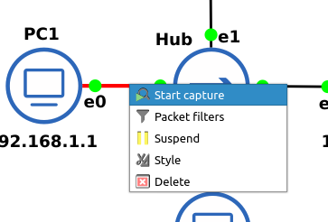
Figure 8 – Opening wireshark on the link between Hub and PC2 - A new Wireshark window will open 3
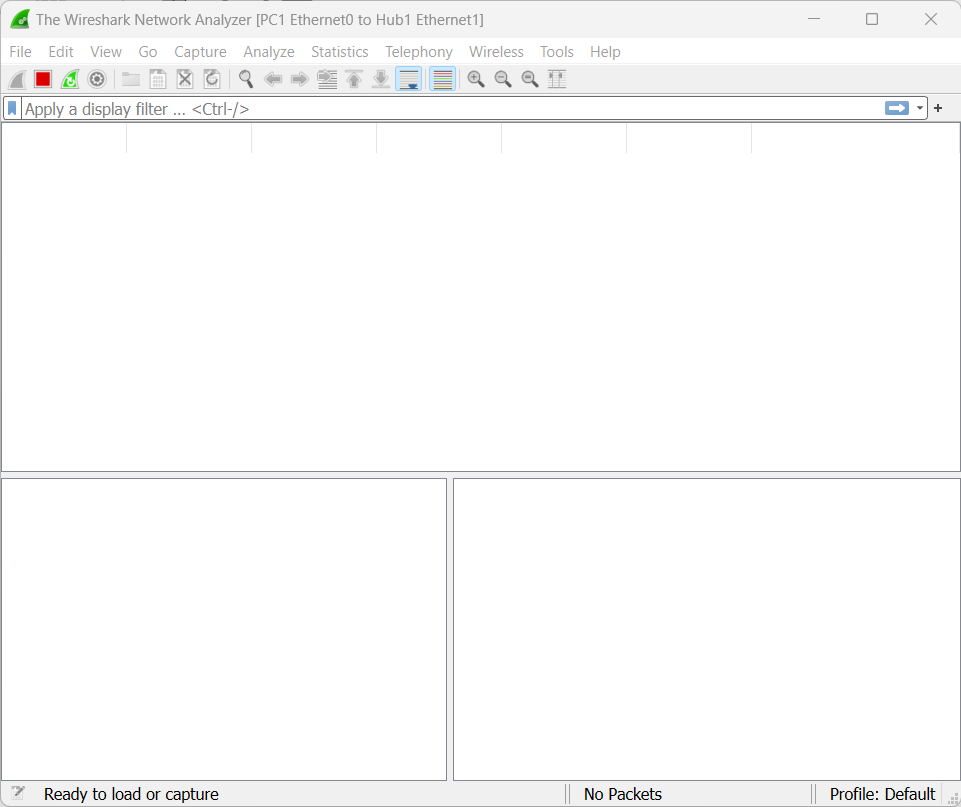
Figure 9 – A new Wireshark is open - A magnifying glass will appear on the wire to show you where the network sniffing is taking place

- Now open the PC1 console and ping the IP address for PC2
> ping 192.168.1.2

Figure 10 – PC1 pinging PC2 - Now watch for the ICMP ping requests and replies in the Wireshark window 1,3

Figure 11 – Captured ICMP packets in Wireshark
NOTE: Don’t be overwhelmed by the information and options available within Wireshark. We are only looking at a small fraction of all possible network traffic. One benefit of using these simulated network environments is to focus only on important information so that we can build up to observing more complicated packet streams in the future.
Phase V – Observe Hub Operations
Hubs are unique in that when any Ethernet packet is sent to them, they retransmit it to every device connected to them. Any PC on the network can see the ethernet packets of every device using the network. This eavesdropping is one reason hubs are rarely used anymore. We will watch how PC1 can eavesdrop on the packets sent between PC2 and PC3.
- Ensure you have an active Wireshark capture on the PC1-Hub connection 3
- Open the console on PC2 and ping PC3
> ping 192.168.1.3
- In Wireshark, observe the packets between PC2 and PC3 1,3

Figure 12 – Captured ICMP packets in Wireshark - Feel free to experiment; try capturing packets between any PC and the hub and then ping different PCs
Phase VI – Replace the hub with a switch
Switches vary widely in function and purpose. However, the one thing they have in common is what makes them different from hubs. Switches only forward Ethernet packets from the source to the destination. We are going to watch what our packets do when we replace a hub with a switch
- Replace the hub with an Ethernet switch
- Right-click on the hub and delete it from the workspace 4
- Click on Browse all devices 4
- Drag the device labeled Ethernet switch to the workspace 4
- Reconnect the computers to the switch by attaching cables
NOTE: Again, don’t worry about what interfaces to use. I personally use interface 1 for PC1, and interface 2 for PC2, etc., but it doesn’t matter for this lab.
- Start a Wireshark capture between the PC3-Switch connection 4
- From the PC1 console, ping PC3
> ping 192.168.1.3
- On Wireshark, you should see the same ICMP request and reply packets as you did earlier 1,4
- From the PC1 console, ping PC2
> ping 192.168.1.2
- Notice how, unlike the hub, you will not see the ping conversation between PC1 and PC3 in the Wireshark capture 1,4
- Feel free to experiment by watching different connections and pinging different devices
End of Lab
Deliverables
Six screenshots are required to receive credit for this exercise:
- Two GNS3 networks with device connections green and neatly labeled
- Ethernet hub being used
- Ethernet switch being used
- Wireshark capture between PC3 and the associated network device
- PC1 pinging PC2 [hub]
- PC2 pinging PC3 [hub]
- PC1 pinging PC2 [switch]
- PC4 pinging PC3 [switch]
Homeworks
Assignment 1 – Build a GNS3 network using 4 PCs and 1 hub
| Device | IP Address with mask |
| PC1 | 56.121.149.10/24 |
| PC2 | 56.121.149.20/24 |
| PC3 | 56.121.149.30/24 |
| PC4 | 56.121.149.40/24 |
Assignment 2 – Build a GNS3 network using 4 PCs and 2 hubs. Connect Hub 1 to Hub 2 and follow the connection table below.
| Hub Number | Device | IP Address with mask |
| 1 | PC1 | 120.107.148.50/24 |
| 1 | PC2 | 120.107.148.75/24 |
| 2 | PC3 | 120.107.148.200/24 |
| 2 | PC4 | 120.107.148.240/24 |
Recommended binary grading criteria:
- Screenshot of GNS3 Working environment where:
- All connections are made according to instructions
- All connections are properly labeled with the correct IP address
- Interface labels are turned on
- Screenshot of Wireshark packet captures taken from the PC3-Hub link:
- PC1 successfully pinging PC2
- PC1 successfully pinging PC4