27 Domain Name System Part 3 – Dynamic DNS
Kyle Wheaton and Jacob Christensen
In Chapter 25, we manually configured our DNS entries with the IP addresses that were statically assigned to our client devices. However, it is uncommon to use static IP assignments, especially in networks with hundreds or even thousands of clients! If we can get our DHCP and ADNS servers to communicate with each other, then IPs can automatically be assigned and our zone files can automatically be populated. This practice is called Dynamic DNS (DDNS).
This lab will expand on the work in Chapter 25 and Chapter 26 to learn how to configure and manage DDNS in a small network environment.
Estimated time for completion: 60 minutes
learning objectives
- Learn how DDNS works on an enterprise network
- Learn how to work with multiple services (DHCP and DNS) on one network
prerequisites
- Chapter 20 – DHCP Linux
- Chapter 24 – DHCP Relay
- Chapter 25 – Domain Name System Part 1
- Chapter 26 – Domain Name System Part 2
deliverables
- Screenshot of BLUE1 (PC1) successfully pinging BLUE2 (PC2) by name
- Screenshot of BLUE2 (PC2) successfully pinging BLUE3 (PC3) by name
- Screenshot of BLUE1 (PC1) successfully performing a DNS query and resolution with the NS1 server via Wireshark monitoring
- Screenshot of Live stream of NS1 reports of the DHCP handshake and zone logs when (BLUE3) PC3 is rebooted
resources
- BIND9 Administrator Reference Manual – https://bind9.readthedocs.io/en/v9.18.16/
- MikroTik RouterOS Documentation – https://help.mikrotik.com/docs/display/ROS/RouterOS
- Configuring Dynamic DNS with BIND9 – https://doncrawley.com/soundtraining.net/files/configuringdynamicdnswithbind9.pdf
- Internet Systems Consortium – The DHCP-DDNS Server – https://kea.readthedocs.io/en/latest/arm/ddns.html
- Tech Tutorials- How to Setup Dynamic DNS (DDNS) using Kea and Bind on Debian or Ubuntu – https://www.techtutorials.tv/sections/linux/how-to-setup-ddns-using-kea-and-bind/
Contributors and testers
Mathew J. Heath Van Horn, PhD, ERAU-Prescott
Kyle Wheaton, Cybersecurity Student, ERAU-Prescott
Phase I – Building the Network Topology
This lab is an extension of the previous two chapters. If you have not completed them yet, it is recommended that you do so first before continuing. By the end your network should look like the following:

- Preliminary step – ensure the KEA server is installed
- Before cloning your Linux Server to be a dedicated DHCP server, ensure that kea-dhcp-ddns-server is installed. It most likely is if you already have KEA installed, but you want to check to prevent HUGE headaches later on. You can check this by starting the VM and in the terminal type
> apt list installed isc-kea-dhcp-ddns-server
- If it is not installed, take the following steps
- Turn off the VM
- Navigate to settings and change the network interface to be NAT
- Start the VM and in the terminal, type the following to install the KEA server
> apt install isc-kea-dhcp-ddns-server
- Once installed, shutdown the VM and switch the network adapter back to its original settings
- Before cloning your Linux Server to be a dedicated DHCP server, ensure that kea-dhcp-ddns-server is installed. It most likely is if you already have KEA installed, but you want to check to prevent HUGE headaches later on. You can check this by starting the VM and in the terminal type
- Clone the Linux Server and call it DHCP
NOTE: In reality, both DHCP and DNS services can operate from the same machine; however, we are separating them into two distinct devices for clarity between the DHCP and DNS services. When students are learning about these services for the first time, having the services on different virtual machines (VMs) enables them to visualize how the services function. Those with limited resources may want to run both services on one VM, but remember to adjust your commands as needed.
- Start GNS3
- Reuse the network that you built in the last chapter and open it in GNS3
- Save the previous lab as a new project; we called ours LAB_27
- Add the newly cloned DHCP server to the GNS3 environment
- Add a DHCP server to the Red network – Ubuntu server (DHCP1)
- Add a switch to the Red network – Ethernet switch
- Connect NS1 and DHCP1 to the switch so that they are on the same LAN
- Your environment should look similar to this
Figure 1 – Final network topology
- Start the DHCP VM and set the static IP address accordingly (in this case, it is 89.30.80.34/29)
- Configure the router to act as a DHCP relay for the Blue subnet. We did this before in Chapter 24, Phase II, Step 1. You can use the same commands, make sure you adjust the interface and IP addresses for the current project
- Remove the static IP addresses from Tiny Core Linux clients by commenting out the rules for static IP assignment
NOTE: Remember, to comment out the instructions in TinyCore, add a # to the beginning of the line
> sudo vi /opt/bootlocal.sh
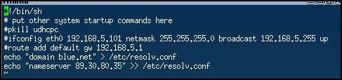
Figure 2 – Removing the static IP address NOTE: Remember to reboot after modifying the bootlocal file
NOTE: Ensure that each client device maintains its unique hostname. If two computers are assigned the same hostname, it will cause issues with the DNS records. To limit future headaches, double-check your hostnames.
- Label and organize your network as necessary
Phase II – Modify the DNS Server
This section assumes that all configurations made in the previous chapter have carried over to this one.
- Start NS1 and login
- Generate a new Transaction Signature (TSIG) key to use to communicate with DHCP1
NOTE: Ensure that you have the bind9-utils package installed! This is most likely already installed if you were using BIND in the previous chapters.
- Change to root
> sudo -i
- Change directories to where the key needs to reside
> cd /etc/bind
- Generate a security key using TSIG (Transaction SIGnatures). This key enhances the security of your DNS operations
> tsig-keygen dhcp-dns > dhcp-dns.key
- You can view your key by typing
> cat dhcp-dns.key
It should look similar to Figure 3 below, however your secret key will be different than the one posted here. Do not give your keys out to others. The following key has been modified from the original string.
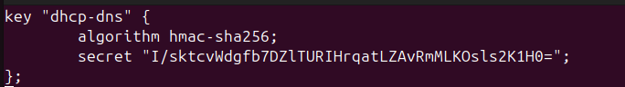
Figure 3 – Generated TSIG key - Leave your root login
> exit
- Change to root
- Modify the file permissions of dhcp-dns[.]key
- Change the owner and group from root to the bind user.
> sudo chown bind:bind /etc/bind/dhcp-dns.key
- Change the file permissions to give read access for the group
> sudo chmod 640 /etc/bind/dhcp-dns.key
- Change the owner and group from root to the bind user.
- Modify the named[.]conf[.]local file
> sudo vi /etc/bind/named.conf.local
- At the beginning of the file, before the zone declarations, include the key
include “/etc/bind/dhcp-dns.key”;

Figure 4 – Include statement of key location - Within each zone declaration (both forward and reverse zones), add the following directive to allow them to be updated with a new policy.
NOTE: The correct amount of spaces may not appear in the CLI text due to formatting, but you can reference the configuration below it. You will notice it starts at character #3 (a.k.a. after 2 spaces), and ‘grant’ begins at character #9.
> update-policy {
grant dhcp-dns wildcard *.red.net A DHCID;
};> update-policy {
grant dhcp-dns wildcard *.80.30.89.in-addr.arpa PTR DHCID;
};
Figure 5 – Update policy for each zone declaration NOTE: The DHCIDs are required by KEA for both forward (A) and reverse (PTR) records. It allows the server(s) to identify unique clients when updates are made to its records.
- Save and exit the editor
- Verify the configuration settings for any errors
> named-checkconf
- At the beginning of the file, before the zone declarations, include the key
- Add a new static entry in the red[.]net zone files for DHCP1
- Modify the forward lookup zone file. Don’t forget to increase the serial count for each save.
> sudo vi /var/lib/bind/db.red.net

Figure 6 – Updating static forward DNS entry - Modify the reverse lookup zone file
> sudo vi /var/lib/bind/db.red.net.rev

Figure 7 – Updating static reverse DNS entry
- Modify the forward lookup zone file. Don’t forget to increase the serial count for each save.
- Remove all client static entries in the blue[.]net zone files
- Modify the forward lookup zone file
> sudo vi /var/lib/bind/db.blue.net

Figure 8 – Purging static forward DNS entries for an internal subnet - Modify the reverse lookup zone file
> vi /var/lib/bind/db.blue.net.rev
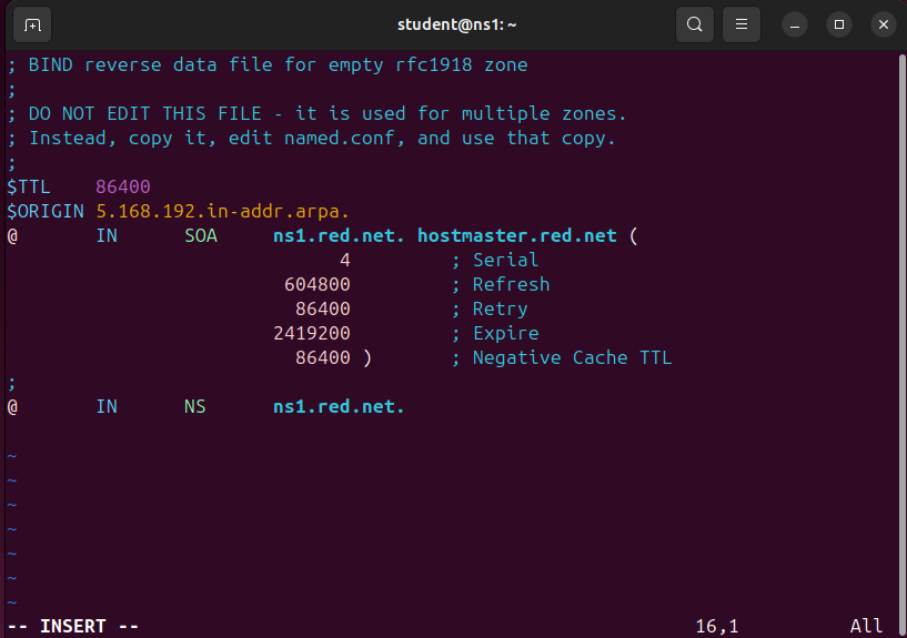
Figure 9 – Purging static reverse DNS entries for an internal subnet
- Modify the forward lookup zone file
- Restart the DNS server and verify that it is running
> sudo systemctl restart named.service
> systemctl status named.service
NOTE: Errors at this stage are likely due to incorrect permissions on the key file. Ensure that both the owner (bind) and group (bind) can read the file.
- Start and enable Systemd’s time synchronization daemon
> sudo systemctl start systemd-timesyncd.service
> sudo systemctl enable systemd-timesyncd.service
Phase III – Configuring the DHCP Server
The following section outlines the configuration of the DHCP daemon for the network. This will also give some practice on transferring files to another machine so the same secret key is on both the DNS and DHCP server.
- Start DHCP1 and login
- Modify the machine’s hostname to dhcp1 and restart the machine from the terminal.
> sudo hostnamectl hostname dhcp1
- Modify the netplan for DNS – Refer to (Chapter 25, Phase III, Step 3)
- Verify that the name server information is correctly pointing towards ns1 (89.30.80.35) and that the current domain is red[.]net
> resolvectl status

Figure 10 – Output of resolve status
- Modify the machine’s hostname to dhcp1 and restart the machine from the terminal.
- Having all elements in a network synchronized to the same time is critical. SNTP clients provide this service. Linux uses Systemd’s timesync daemon to provide SNTP packets. Start it and enable (start on boot) the service by typing
> systemctl start systemd-timesyncd.service
> systemctl enable systemd-timesyncd.service
- Transfer the key file from NS1 to the primary user’s home directory in DHCP1 if you cannot copy-paste the private key.
NOTE: The default user for the machines in this lab is student; be sure to change the following commands as necessary to suit your machine(s). If you are using one machine for both DHCP and DNS you can skip this part. This section can help those who do not have a bidirectional clipboard enabled.
- Login to the NS1 terminal from the DHCP server
> ssh student@89.30.80.35
NOTE: You should see the hostname change to ns1 when you login successfully.
- Switch to the root user
> sudo su
- Use the Secure Copy (SCP) command to make a copy of dhcp-dns[.]key to the primary user of DHCP1
> scp /etc/bind/dhcp-dns.key student@89.30.80.34:/home/student
- Exit from root
> exit
- Exit the SSH session
> exit
- Verify that you see the key in your home directory
> ls -l ~
- Login to the NS1 terminal from the DHCP server
- Modify the permissions for the key file on the DHCP server
- Ensure that the owner and group are both root
> sudo chown root:root ~/dhcp-dns.key
- Change the permissions to remove read access from others
> sudo chmod 640 ~/dhcp-dns.key
- Move the file to the DHCP configuration directory
> sudo mv ~/dhcp-dns.key /etc/kea
- KEA reads keys following a JSON format, however the current dhcp-dns[.]key is not in JSON. Modify the extension of the file from [.]key to [.]json by first going into the /etc/kea directory
> cd /etc/kea
> mv dhcp-dns.key dhcp-dns.json
- Ensure that the owner and group are both root
- Format the file to the following. This file will be used in a later step
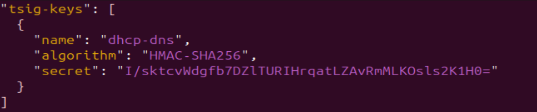
Figure 11 – TSIG key file formatted in JSON NOTE: Ensure it is exactly in this JSON format. Though your key is likely different, transferring it from NS1 allows an easier way to see and copy the “secret” instead of going back and forth between machines to type each character.
- Transfer the key file from NS1 to the primary user’s home directory in DHCP1 if you cannot copy-paste the private key.
- Modify the KEA DHCP configuration file to support both subnets and their domains
> sudo vi /etc/kea/kea-dhcp4.conf
- Include global parameters that apply to all subnets and the new RNDC key file
NOTE: Use your information that applies to your network. Tester HVH used red.net (10.10.10.0/29) and blue.net (192.168.5.0/24). Tester Kyle used red.net (89.30.80.32/29) and blue.net (192.168.5.0/24). Also, remember KEA uses a JSON format. When taking a screenshot of the full file, the text appeared too small, so we broke it up into three parts. Keep in mind that each part is part of the same file
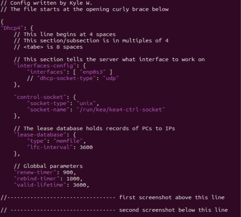
Figure 12 – Part one of long configuration - Add the pools, router data, and the DDNS suffix for each subnet included in our BIND9 DNS server
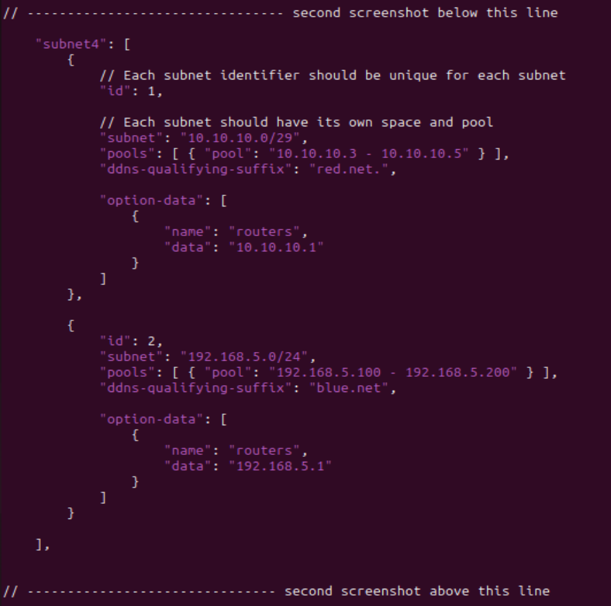
Figure 13 – Part two of long configuration - Add updates for Dynamic DNS (DDNS)
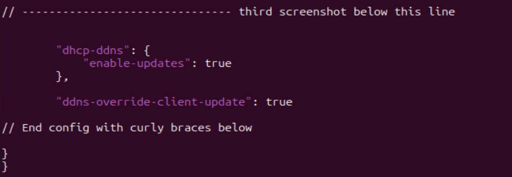
Figure 14 – Part three of long configuration - Check the file for any errors
> kea-dhcp4 -t /etc/kea/kea-dhcp4.conf
NOTE: Read the output of the file check command. There is a difference between errors (something wrong), warnings (something not configured), and info (just information). You will get warnings about QUEUE CONTROL and MULTI-THREADING because we didn’t configure those options.
- Here is an example of the full configuration for reference
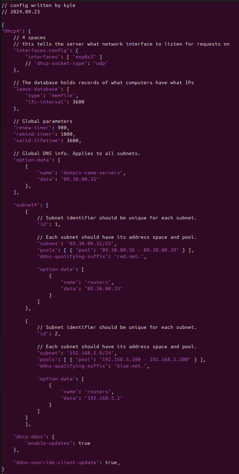
Figure 15 – Full DHCP config - Restart the DHCP service
> sudo systemctl restart kea-dhcp4-server.service
- Check its status
> systemctl status kea-dhcp4-server.service
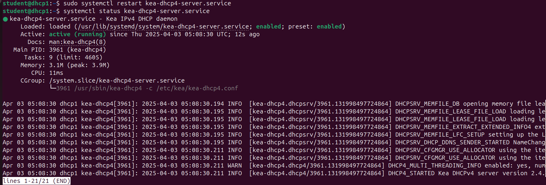
Figure 16 – Status of DHCP service - Ensure that each client in blue[.]net is able to receive an IP address.
- Login to the terminal of PC1
- Verify it was assigned an IP address
> ifconfig

Figure 17 – Tiny Core static IP verification - Repeat for the other two client devices
- Include global parameters that apply to all subnets and the new RNDC key file
Phase IV – Configuring the DDNS file on the DHCP server
The Dynamic DNS (DDNS) file is used by KEA to ensure that updated IP addresses are correctly mapped to their corresponding domain names. Since DHCP leases IP addresses for limited durations, a device’s IP may change over time. In the previous chapters, the A and PTR records were statically configured to map IPs to domain names (e.g., blue.net). However, in this chapter, those records must be dynamically updated as the DHCP server assigns new leases. This process automates both IP address assignment and real-time DNS record updates.
- Edit KEA’s DDNS file
> sudo vi /etc/kea/kea-dhcp-ddns.conf
- Add global parameters to the file. Note that the IP address is a loopback
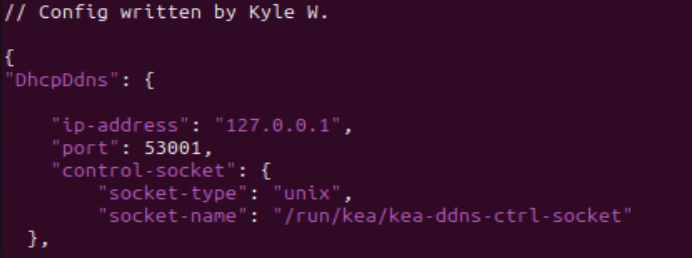
Figure 18 – Beginning of KEA DDNS file - Include the dhcp-dns[.]json file into this configuration below the global parameters
> <?include “/etc/kea/dhcp-dns.json”?>
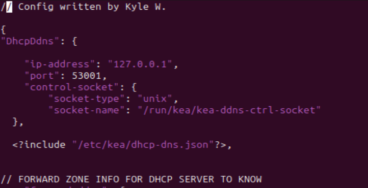
Figure 19 – Addition of include statement under DDNS global parameters 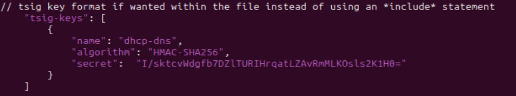
Figure 20 – TSIG key format within DDNS file NOTE: It is best practice to include a file for key(s). However, KEA allows TSIG keys to be in the DDNS file if wanted. It is best practice because messing with a large JSON file has a higher potential for mistakes to be made. This reduces the risk. If you want to include it in the file, use the below configuration for reference.
- Add the forward lookup information
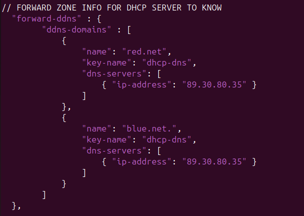
Figure 21 – DDNS forward lookup information - Add the reverse lookup information
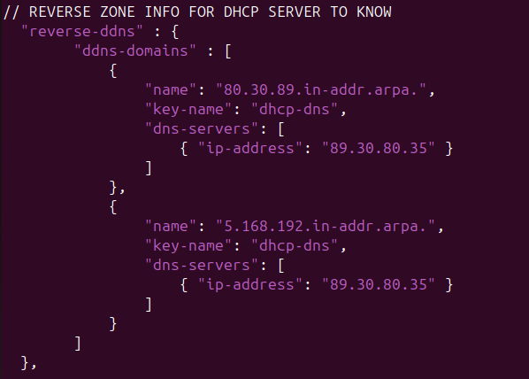
Figure 22 – DDNS reverse lookup information - Add KEA’s default logging information if it is not already there as the last step. We are keeping the default values for everything
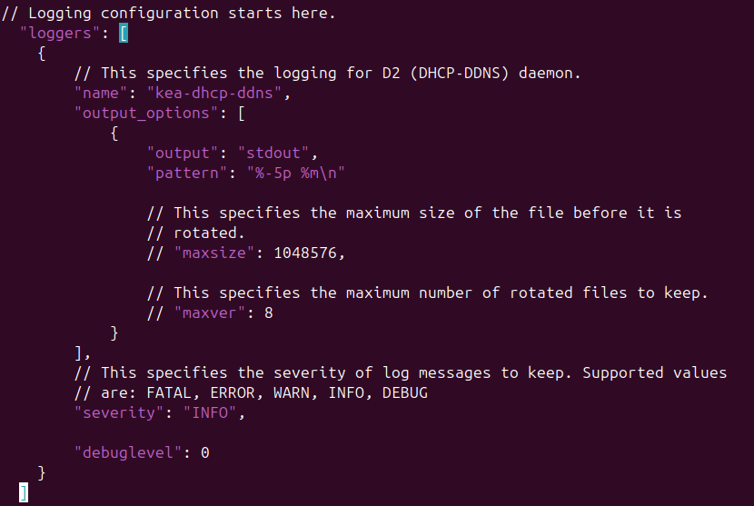
Figure 23 – DDNS default logging information - Final configuration reference
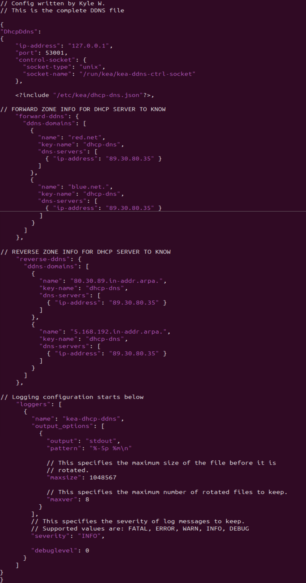
Figure 24 – Final DDNS config
- Add global parameters to the file. Note that the IP address is a loopback
- Modify permissions of the file so KEA can access it
> sudo chown _kea:root kea-dhcp-ddns.conf”
- Check the configuration file for any errors
> kea-dhcp-ddns -t kea-dhcp-ddns.conf
NOTE: If you encounter an error stating “Can’t open include file /etc/kea/dhcp-dns.json,” simply rerun the command with sudo or root privileges. This is because we just changed the file permissions so only root and kea can access it.
- Restart the service and check its status
> sudo systemctl restart kea-dhcp-ddns-server.service
> systemctl status isc-kea-dhcp-ddns-server.service
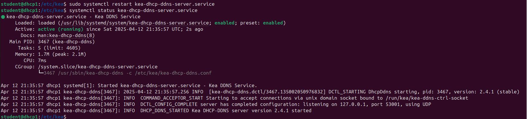
Figure 25 – KEA DDNS service status - Troubleshoot as necessary before proceeding to the next section
Phase V – Wireshark Captures
Now that our network is set up, let’s watch some live packet captures to see what DNS queries look like in action.
- Start a Wireshark capture between NS1 and the switch
- Test the dynamic DNS updates
- In Wireshark, filter for DNS. Then start up one of the TinyCore computers.

Figure 26 – DNS traffic - In the NS1 terminal, start monitoring the system log
> tail -f /var/log/syslog
- Reboot PC1 and watch the logs for the DHCP handshake and zone file mapping

Figure 27 – Output of logs - In the Wireshark window, you should see *DNS Update* packets

Figure 28 – Wireshark DNS updates - Repeat for the other two PC clients
NOTE: You can request new IP address leases in Tiny Core with the following command:
> sudo udhcpc
- In Wireshark, filter for DNS. Then start up one of the TinyCore computers.
- After about 15 minutes, BIND9 will populate the db files with the updated host/IP records
NOTE: By default, this information is stored in a journal file (.JNL) which is located in the same directory as the zone files. The main database files are not frequently updated to increase efficiency.
End of Lab
Deliverables
4 screenshots are needed to receive credit for this exercise:
- BLUE1 (PC1) successfully pinging BLUE2 (PC2) by name as observed on BLUE1 (PC1)
- BLUE2 (PC2) successfully pinging BLUE3 (PC3) by name as observed on BLUE2 (PC2)
- BLUE1 (PC1) successfully performing a DNS query and resolution with the NS1 server via Wireshark monitoring
- Live stream of NS1 reports of the DHCP handshake and zone logs when (BLUE3) PC3 is rebooted
Homeworks
Assignment 1 – Add the GREEN network to the workspace on the existing router
- Minimize wasted address space for 313 machines
- Add 3 Tiny Core machines to prove functionality
- It is okay to turn off the 3 BLUE end devices to save VM resources
- Modify the router, DHCP1, and NS1 to provide the same functionality to the GREEN network that exists on the BLUE network
Assignment 2 – Complete Assignment 1 and then add a PURPLE network
- Minimize wasted address space for 512 machines
- Add 3 Tiny Core machines to prove functionality
- It is okay to turn off the other end devices to save VM resources
- Modify the router, DHCP1, and NS1 to provide the same functionality to the PURPLE network that exists on the BLUE and GREEN networks
RECOMMENDED GRADING CRITERIA: Same as deliverables with appropriate substitutions for added devices.