20 Dynamic Host Configuration Protocol – Linux
Jacob Christensen and Dante Rocca
Dynamic Host Configuration Protocol (DHCP) is an interactive client-server protocol that automatically provides a host (PC, Laptop, Phone, etc) with an Internet Protocol (IP) address upon request. The purpose of this activity is for learners to see DHCP in action instead of just reading about the DHCP handshake theory. A secondary purpose is for learners to experience frustration when hosts do not get a DHCP IP address. Learners can see how the packets move and where they may get hung up while working on making DHCP function correctly on their network. Finally, learners can see Address Resolution Protocol (ARP) in action. While DHCP occurs when a host requests an IP address for an existing MAC address, ARP occurs when a host has an IP address but is unsure what MAC address it belongs to.
Estimated time for completion: 60 minutes
Learning objectives
- Successfully deploy a DHCP solution using Linux on an enterprise network
- Capture and Observe DHCP packets using Wireshark
- Capture and Observe ARP packets using Wireshark
- Successfully add hosts to an enterprise network and receive IP addresses automatically
Prerequisites
Deliverables
- 5 Screenshots:
- Wireshark – DHCP Packets for PC1
- Wireshark – DHCP Packets for PC2
- Wireshark – ARP Packets for PC1/PC2
- GNS3 Workspace
- Configuration of DHCP Daemon
Resources
Contributors and testers
- Mathew J. Heath Van Horn, PhD
Phase I -Build the Network Topology
The following are steps to set up the learning environment to better understand DHCP. Since learners have performed many of these tasks in other labs, we have taken liberties to reduce the number of steps and screenshots for repeated material. If you are confused about what you’ve been asked to do, please review the appropriate chapter of this book.
Your final network will look like the following:

- Start GNS3
- Create a new project and name it whatever you want. For this example, we called it Lab4
- Build a new LAN with an overall network space of 200.200.200.0/24
Self Check:
- Use two VPCS devices for PC1 and PC2
- Add an Ethernet switch
- Add an Ubuntu Server VM and rename it to “DHCP-Server”
NOTE: Ensure that the Allow GNS3 to use any configured VirtualBox adapter check box is selected for all VMs added to GNS3. Refer to Chapter 6 – Adding a Virtual Machine to GNS3
- Connect the server and PCs to the switch
- Label and organize your network as necessary

Figure 2 – Basic network topology
Phase II – Configure the DHCP Server
This lab requires that kea be installed on your VM. Verify this with the following command. Refer to Chapter 7 for instructions on installing the necessary packages from the APT repository. If you are already familiar with DHCP configuration, please feel free to use those and explore other solutions too.
> apt list kea

Ensure that yours also says “[installed]” next to the output.
NOTE: For those who have limited computer power/resources, consider using a TinyCore VM as your primary Linux server, as covered in Chapter 9.
Moving forward, managing Linux boxes will become a staple in our networks. While this might be intimidating for those who are new to CLI environments, be assured that you will quickly learn. However, it is a good idea to refresh basic terminal navigation skills online before continuing.
- Start the DHCP Server and give it a minute or two to boot
- Login: student
- Password: Security1
NOTE: Learners unfamiliar with Linux must know that Linux CLI will NOT move the cursor as you type the password. This is a security countermeasure to prevent shoulder-surfing. Even if an observer can’t see the characters being typed in the password, knowing the number of characters in the password makes brute-force password hacking easier. Therefore, if the cursor doesn’t move, nobody can count the number of characters used in the password by watching the screen.
Making Backups
Creating backups before editing critical files (such as configuration files) is always good practice. When needed, they will save you lots of time and headaches, so make it a habit now so you don’t regret it later.
Make a new backup folder in your home directory.
> mkdir ~/backups
Verify it was successfully created.
> ls ~/ | grep backups

Figure 4 – Backups file created Make a copy of a file to the backups folder (sudo may be necessary depending on the security of the file).
> cp /path/to/file/example.conf ~/backups/
Restore the file if needed.
> cp ~/backups/example.conf /path/to/file/
NOTE: obviously “/path/to/file/” and “example.conf” are placeholders. Adjust them as necessary to your situation.
- Configure the server’s interface with the static IP of 200.200.200.254 on a /24 network
- Identify the network configuration file
> ls /etc/netplan/
NOTE: The netplan configuration file will always be a .YAML in this directory; however, the name may change between releases or user modification. As of writing this textbook, I am using Ubuntu 22.04.X LTS. The default configuration file name for netplan is 00-installer-config.yaml. Adjust as necessary.

Figure 5 – looking for the name of the YAML file - Edit the YAML file to match the example provided below
> sudo vi /etc/netplan/00-installer-config.yaml

Figure 6 – Ubuntu netplan configuration Command Description enp0s3 This is the name of interface you want to configure with options indented after. This can be checked with the command ip address show. Adjust as necessary. optional Determines whether the system should wait to boot until the specified interface is configured. If you are getting an error on boot concerning “waiting for network configuration”, ensure that this value is set to ‘true’. dhcp4 Determines whether the specified interface can dynamically receive IP addresses from a DHCP server. addresses Set static IP address value(s) to the specified interface. NOTE: You can use any preferred text editor, but it is recommended that you become familiar with Vi, which is installed by default on even the most minimal Linux distributions.
Basic commands:
– Press i to enter Insert (editor) mode.
– Press Esc to return to Command mode.
– Type :wq in Command mode to save (write) and exit back to the terminal.
– Type :q! in Command mode to exit without saving. - Apply the changes
> netplan try
NOTE: Proper spacing in this file is critical. If an error is thrown, ensure your file matches the one provided. Double and triple-check for spelling errors.
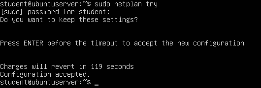
Figure 7 – Try the new netplan you wrote - Verify the IP address of the DHCP Server was taken and that the ethernet card has a state of UP
> ip -c addr
NOTE: Some testers have reported that you might not get the above information when you type ip addr. Some interfaces, even virtual ones, need to think a cable is plugged in. Ensure that a cable is connected from the server to the switch.
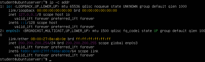
Figure 8 – Showing the IP address has been assigned to the server - In GNS3, add a label next to DHCP Server with its new host address
- Identify the network configuration file
- Modify the DHCP Server configuration file as shown below
> sudo vi /etc/kea/kea-dhcp4.conf

Figure 9 – Example DHCP Daemon Configuration NOTE: You can delete most of the lines in the file by typing dG or you can append it as appropriate. Your choice.
- When editing system services, it is good practice to reload the manager with updated configurations
> sudo systemctl daemon-reload
- Verify that the server is enabled so that it starts on boot
> systemctl is-enabled kea-dhcp4-server
- Enable the service if necessary
> sudo systemctl enable kea-dhcp4-server
- Enable the service if necessary
- Start the DHCP daemon
> sudo systemctl start kea-dhcp4-server
- Verify the server is running (type Q to quit)
> sudo systemctl status kea-dhcp4-server

Figure 10 – DHCP Server Status NOTE: If you get an error, it is likely that there was a syntax error in your configuration file or the unit file was not updated correctly. You can try restarting the service with the following command:
> sudo systemctl restart kea-dhcp4-server
NOTE: If a restart doesn’t work, you can view the details of the failure in the logs by typing the following command
> journalctl -xeu kea-dhcp4-server
Switch Description -x / –catalog Provide more verbose/explanatory log and error messages. -e / –pager-end Jump to the end of the log file. -u / –unit Specify the service to view the logs messages of. - Congratulations! This machine is now acting as the DHCP server for any end-device client (laptop, PC, phone, etc.) that connects to the network
Phase III – Watch DHCP in Action
Remember, DHCP is a network management protocol that allows hosts to obtain IP addresses automatically upon request. It uses the User Datagram Protocol (UDP) and the server listens on port number 67 and the client listens on port 68.
- The end device (also called a client) will send out a discovery request (e.g. “Is anyone out there handing out names?”)
- The server sees the discover request and sends out a DHCP offer (e.g. “Yes, I see you, try 20.20.20.25”).
- The client will then send a request packet (e.g. “Can I really use this name?”).
- Finally, the server will send an acknowledgment packet (e.g., “20.20.20.25 is all yours, man”).

- Navigate to the GNS3 workspace
- Initialize a new Wireshark session on the PC1-Switch link by right-clicking on the link
- Start PC1, open its console, and request a new IP address
> ip dhcp
NOTE: If successful, you should see an output that looks similar to the following:

Figure 11 – DHCP request on VPCS If you are unable to see the DORA (discover, offer, request, acknowledge) string in the VPCS console, either the Linux box is unreachable or the DHCP daemon is offline. Go back and troubleshoot before moving forward. If all else fails, try rebooting the server or restarting GNS3 entirely.
- Now go back to Wireshark and look at the packets captured between PC1 and the switch
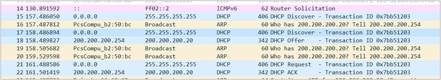
Figure 12 – Observing Wireshark - Filter for only DHCP packets

Figure 13 – Wireshark DHCP handshake - [DHCP Discover]
Look at the Discover packets. There is at least 1, but there could be more depending on lag. In this example, we see on Wireshark that someone on the network basically says “HELLLOOOO! I don’t know who I am (0.0.0.0). Is there anyone out there handing out IP addresses? Please speak to me!”
– Source: 0.0.0.0 (Who am I?)
– Destination: 255.255.255.255 (Who’s out there?)
– MAC Address: 00:50:79:66:68:00 (This is what my face looks like) - [DHCP Offer]
Now, look at the DHCP offer packets. It’s like our DHCP server (200.200.200.254) is saying, “Hey buddy I’m here, and if you need a name you can use this one (200.200.200.###).”
– Source: 200.200.200.254 (I’m here)
– Destination: 200.200.200.20 (Here’s a name that’s available) - [DHCP Request]
Then the next packet should be our no-name PC saying “Oh, me me me, I like the name 200.200.200.###” in a DHCP request packet.
– Source: 0.0.0.0 (I still don’t have an official name yet)
– Destination: 255.255.255.255 (If you’re still out there I want that name) - [DHCP ACK]
Finally, our server acknowledges PC1s eagerness and says, “Ya buddy you are now 200.200.200.### from now on and not just some schmo (0.0.0.0) who looks like 00:50:79:66:68:00.”
– 200.200.200.254 (I’m still here)
– 200.200.200.20 (You’re officially known as host .20 on this network)
- Filter for only DHCP packets
- Repeat the above steps to assign PC2 its own IP address
- Return to GNS3 and update the VPCS labels with the new IP addresses they were assigned
Figure 14 – GNS3 network labeled
Phase IV – Watch ARP in Use
Remember, network packets are passed by MAC addresses in Layer 2 of the OSI Model. Since we manually configured the static IP addresses on the router and the server, the network doesn’t know which IPv4 address goes to which NIC on the individual hosts. The networks now see each other and say, “Who are you?” to each other. In this example, we can see 200.200.200.254 (our DHCP server) asking who has an IPv4 address of 200.200.200.1 (our server) and vice versa. You can see that 200.200.200.254 responds and says “My Layer 2 name is 08:00:27:b2:50:bc”. Don’t worry about the other packets you see currently. Just get used to what ARP looks like so you can understand it when you see it again in the future.
- Return to the PC1-Switch Wireshark capture window and filter for ARP packets

Figure 15 – ARP Packet Capture using Wireshark - [Gratuitous ARP]
After a PC receives an IP address from the subnet’s DHCP server, it may broadcast (ff:ff:ff:ff:ff:ff) to all devices on the network that its MAC address (00:50:79:66:68:01) now belongs to a specific layer 3 address (200.200.200.20). This is known as a “gratuitous ARP response”, since it was sent unprompted by any specific ARP request.
– Source: 00:50:79:66:68:01 (This is my face)
– Destination: ff:ff:ff:ff:ff:ff (Hey everyone who can hear me!)
– IP Address: 200.200.200.20 (This is my name now!) - [Who has?]
If a device wants to know who currently owns an IP address, it may send an ARP request to specific MAC address or broadcast the message to all devices. In this example, the DCHP server (08:00:27:2a:17:11) wants to know if PC1 (00:50:79:66:68:01) still holds the IP address 200.200.200.20. This is known as an ARP request.
– Source: 08:00:27:2a:17:11 (This is my face)
– Destination: 00:50:79:66:68:01 (Hey you there)
– Sender IP Address: 200.200.200.254 (This is my name)
– Target IP Address: 200.200.200.20 (Is this your name?) - [ARP Reply]
In response to an ARP request packet, the device that hold the target IP will respond with an ARP relply.
– Sender IP Address: 200.200.200.20 (This is my name…)
– Source: 00:50:79:66:68:01 (… associated with this face)
- [Gratuitous ARP]
- Use this opportunity to analyze Wireshark packets and get comfortable with how DHCP and ARP work on a live network
End of Lab
Deliverables
5 screenshots are needed to receive credit for this exercise:
- Wireshark – DHCP Packets for PC1
- Wireshark – DHCP Packets for PC2
- Wireshark – ARP Packets for PC1/PC2
- GNS3 Workspace
- Configuration of DHCP Daemon
Homeworks
Assignment 1 – Combined network traffic watching
- Turn off all devices
- Replace the switch with a hub and reconnect all devices
- Monitor any of the PCs with Wireshark and capture ARP, DHCP, and ICMP packets for each PC as you turn devices back on
- RECOMMENDED GRADING CRITERIA
- Screenshot of GNS3 environment with everything labeled
- Screenshot of Server-PC1 ARP from PC2-Hub link
- Screenshot of Server-PC1 DHCP from PC2-Hub link
- Screenshot of Server-PC1 ICMPfrom PC2-Hub link
Assignment 2 – Reconfigure the DHCP server
- Figure out the number of devices that can be attached to the switch
- Generate a random IP address and choose a subnet that will allow the use of all the switch connections with as few wasted IP addresses as possible
- Reconfigure the network to use these new network addresses
- Reconfigure the DHCP settings to issue IPv4 address in this new space
- RECOMMENDED GRADING CRITERIA
- Screenshot of the DHCP configuration file
- Screenshot of the GNS3 workspace
- Screenshot of DHCP of one PC
- Screenshot of ICMP of one PC