22 Dynamic Host Configuration Protocol – MikroTik CHR
Jacob Christensen
Thus far, we’ve explored two approaches to integrating DHCP servers into a network using both Linux and Windows as dedicated servers. This chapter introduces yet another method for deploying DHCP, in the form of a router. This proves particularly handy in scenarios where a quick and easy solution is required. Configuring DHCP in this manner offers rapid deployment and simplicity, making it ideal fit smaller network environments.
Estimated time for completion: 10 minutes
Learning objectives
- Successfully deploy a DHCP solution using a MikroTik router on an enterprise network
- Capture and Observe DHCP packets using Wireshark
- Capture and Observe ARP packets using Wireshark
- Successfully add hosts to an enterprise network and receive IP addresses automatically
Prerequisites
Deliverables
Five screenshots are required:
- Neatly labeled and organized GNS3 workspace
- MikroTik router configuration
- Screenshot of Wireshark
- DHCP packets for PC1
- DHCP packets for PC2
- PC1 pinging PC2
Resources
Contributors and testers
- Dante Rocca, Cybersecurity Student, ERAU-Prescott
- Kyle Wheaton, Cybersecurity Student, ERAU-Prescott
Phase I -Build the Network Topology
The following steps are to create a baseline environment for completing the lab. It makes assumptions about learner knowledge from completing previous labs.
Your final network will look like the following:
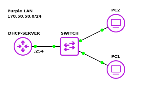
- Start GNS3
- Create a new project: LAB_06
- Build a Class C subnet with the network address 178.58.58.0/24
- Two client devices – VPCS
- One switch – Ethernet switch
- One DHCP server – MikroTik router
NOTE: The MikroTik CHR version used when making this lab was 7.11.3.
- Connect the PCs to the switch
- Connect port ether1 on the router to the switch
- Label and organize your network as necessary
Phase II – Configuring the MikroTik Router
Once the network is built we need to configure the router to act as our DHCP server.
- Start the MikroTik router and open its console
- Change the hostname to reflect the router’s primary purpose
> system identity set name=DHCP-SERVER
- Remove the default DHCP listener on ether1
> ip dhcp-client remove 0
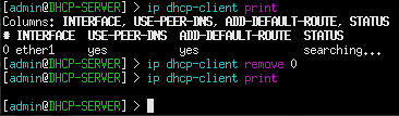
Figure 2 – Removing the DHCP client - Assign a static IP address to its running interface
> ip address add address=178.58.58.254/24 interface=ether1
NOTE: In this example, I have ether1 connected to the switch. Remember to adjust this to be applicable for your environment.
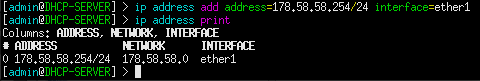
Figure 3 – Assigned IPv4 addresses - Use the built-in setup wizard to configure the DHCP server
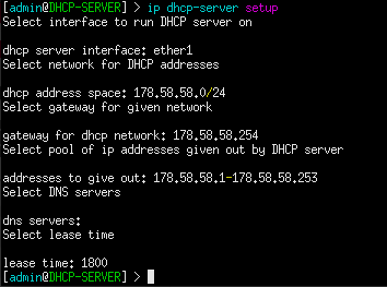
Figure 4 – DHCP Server setup wizard > ip dhcp-server setup
- dhcp server interface: ether1
- dhcp address space: 178.58.58.0/24
- gateway for dhcp network: 178.58.58.254
- addresses to give out: 178.58.58.1-178.58.58.253
- dns servers: (none just hit <Enter> )
- lease time: 1800
- Change the hostname to reflect the router’s primary purpose
- Test the DHCP service on the network
- From PC1, request a new host address
> ip dhcp
- From PC2, request a new host address
> ip dhcp
- From PC1, request a new host address
- From PC1, ping PC2 to test connectivity
End of Lab
Deliverables
Five screenshots are required to receive credit for this exercise:
- GNS3 workspace with all devices labeled
- MikroTik router configuration
- Wireshark capture of PC1 devices getting and receiving DHCP IPv4 addresses
- Wireshark capture of PC2 devices getting and receiving DHCP IPv4 addresses
- Wireshark caputre of PC1 pinging PC2
Homework
Assignment 1 – Create a LAN for 43 hosts with a Mikrotik DHCP server while minimizing unused IP addresses
- Used a randomized network address
- There’s no need to put in all 43 host just show the setup process for the DHCP server and that it is working with at least two hosts
- RECOMMENDED GRADING CRITERIA
- Screenshot of GNS3 Environment
- Screenshot of end devices receiving IP addresses
- Screenshot of DHCP setup process
Assignment 2 – Use the Mikrotik router as both a DHCP server and a router
- Add another LAN attached to the same Mikrotik router
- Ensure devices on both LANs use the Mikrotik router as a DHCP server
- Ensure devices on both LANs can contact each other
- RECOMMENDED GRADING CRITERIA
- Screenshot of GNS3 Environment
- Screenshot of an end device on the first LAN receiving an IP address
- Screenshot of an end device on the second LAN receiving an IP address
- Screenshot of a device on one LAN pinging a device on the other LAN