31 Dynamic Networking – Border Gateway Protocol
Jacob Christensen and Mathew J. Heath Van Horn, PhD
Although OSPF has fast convergence rates, it can put a lot of strain on computing resources as networks become larger, making it better suited within a LAN or autonomous system (AS). The Border Gateway Protocol (BGP) on the other hand is the only networking protocol currently in use that can handle the Internet’s ever-increasing size and complexity while minimizing overhead.
Estimated time for completion: 65 minutes
Learning objectives
- Learn how to implement BGP in an enterprise network
- Be able to identify and understand BGP packets in Wireshark
prerequisites
deliverables
- Screenshot of GNS3 Workspace with all devices labeled
- Wireshark capture of the TCP and BGP packets being exchanged
- Wireshark view of the keep alive messages
- Wireshark view of the update packets with the NLRI view
resources
contributors and testers
- Kyle Wheaton, Cybersecurity student, ERAU-Prescott
A note from the authors:
At the beginning of this book, we focused on how end devices communicate with each other. We used overly-simplistic definitions, but they helped organize our focus on the topics covered. If we abstract ourselves into a video-game perspective looking down on our sims, we can zoom in and out and break our network functions into some abstract views. This is still an oversimplification of how networks work, but it helps us conceptualize what we have learned and where we are going in our learning.
- 100′ level
- Immediate area or workspace, such as an office work center or a living room
- LAN – End devices connected to each other by a switch or a hub
- We see many end devices
- 500′ level
- Multiple individual workspaces connected such as an office department or a home
- Network – LANs connected to each other by a router
- We see fewer end devices
- 5,000′ level
- We use routers to extend our connectivity such as neighborhoods or a corporate enterprise
- Enterprise Network – Routers connected to each other within one enterprise
- We see one end device

In this chapter, we are going to zoom out once again to about 20,000′ and look at how our enterprise connects to other enterprises. We will abstract our Enterprise Network and now call it an Autonomous System. At this point, our video-game view would not see any end devices or LAN devices such as switches and routers.
However, we still think learners need to see how end devices share information with each other through the network. Therefore, in this chapter, we are going to abstract some of the intermediary functions we have already learned. Here are some things to keep in mind as you complete this lab:
- A host machine is used to represent an entire LAN
- A router is used to represent an entire Network
- A border router is used to represent an Enterprise Network (Autonomous System)
Phase I – Building the Network Topology
The following steps are to create a baseline for completing the lab. It makes assumptions about learner knowledge from completing previous labs.
Terminology used in this lab:
- Autonomous System (AS) – A network or cluster of networks following the same routing policies. Typically, each AS is controlled by a single entity.
- Autonomous System Number (ASN) – A 16-bit integer assigned to an AS for identification purposes.
- Autonomous System Border Router (ASBR) – Routers at the edge of an AS that connects to external networks.
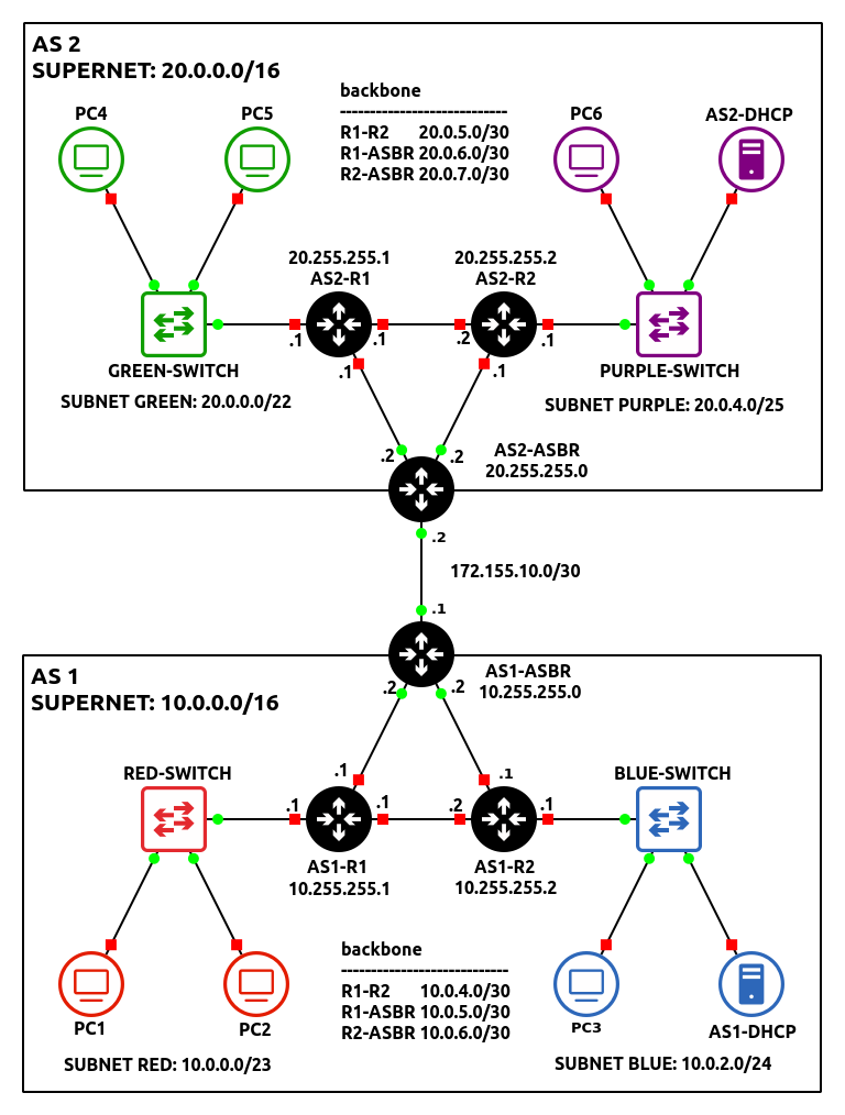
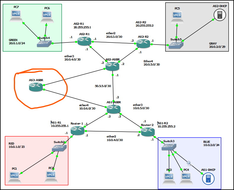
By the end of this chapter, your network topology should look like the following:
- Start GNS3
- Open the previous Chapter 30 lab
- Save it as a new project and name it anything you like. We named ours Lab 31
- Modify the network environment to function as AS-1
- Remove the Gray subnet
- Replace PC4 with a DHCP server
- Router3 will now act as the networks border router (AS1-ASBR)
NOTE: In this example, AS1-ASBR’s Router ID will be 10.255.255.0. If you are reusing a previously configured router, and want to change the router-id value, ensure to adjust your previous loopback/OSPF configurations as necessary.
- Adjust OSPF to only operate only on internal facing ethernet ports
NOTE: Remember that the purpose of a border router is to manage packets that are leaving (egress) or entering (ingress) through a network. With this in mind, some of its ports will be categorized as internal and external. Below is a simplified example of the network we are trying to build to illustrate this idea clearly.
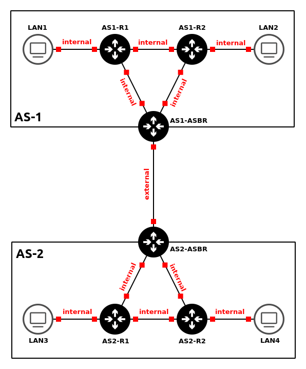
Figure 3 – Internal vs external links In the previous chapter, we configured OSPF to operate on ALL active interfaces.
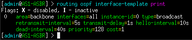
Figure 4 – OSPF configured on all interfaces However, here we only want to share routes that are within the AS-1 network. Therefore, OSPF should only be configured to operate on internal interfaces. In this example, when we look at the console for AS1-R3/AS1-ASBR, we see that ether2 is connected to AS1-R1 and ether3 is connected to AS1-R2. These are inward-facing (internal) ports. In contrast, ether1 will be used as the network’s outward-facing (external) interface. Below is my OSPF interface configuration for AS1-ASBR.
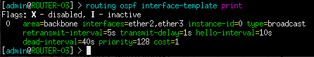
Figure 5 – OSPF configured on select interfaces - Configure AS1-DHCP to service both the Red and Blue subnets
NOTE: Remember to adjust and/or remove your DHCP relays on each router as you modify the network.
- Ensure that all devices can receive IPv4 addresses
- Ensure that all devices can ping one another
- Assign default routes for each internal router that points to AS1-ASBR’s inward-facing addresses
NOTE: In most cases, it is impossible for a router to know the location and hop distance of every single network at all times. Sometimes networks are just too big to store that much information in a single routing table. Because of this, default routes are used to forward packets automatically with unknown/foreign destination addresses (represented as 0.0.0.0/0) to another router who might know the answer. In the context of this network, our internal routers (AS1-R1 and AS1-R2) should only contain records of subnets within the 10.0.0.0/16 supernet, thanks to our OSPF configuration. Therefore, packets trying to reach outside this network should be sent to the border gateway router (AS1-ASBR), which might contain this information.
- Type the following commands in AS1-R1
NOTE: We are assigning two default routes because AS1-ASBR has two inward-facing interfaces. If one does go down, the other will serve as a backup for redundancy. Remember, route priority is based on distance value.
> ip route add dst-address=0.0.0.0/0 gateway=10.0.5.2 distance=1
> ip route add dst-address=0.0.0.0/0 gateway=10.0.4.2 distance=2
- Type the following commands in AS1-R2
> ip route add dst-address=0.0.0.0/0 gateway=10.0.6.2 distance=1
> ip route add dst-address=0.0.0.0/0 gateway=10.0.4.1 distance=2
- Type the following commands in AS1-R1
- Label and organize your network as necessary
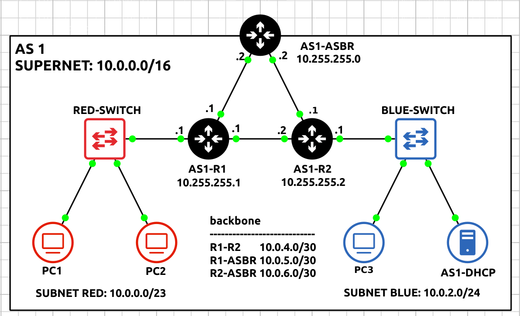
Figure 6 – AS1 network complete
- Build a small network analogous with the following specifications to function as AS-2:
- Class B Supernet – 20.0.0.0/16
Host Range Host Lower Bound 20.0.0.1 Host Upper Bound 20.0.255.254 - Subnet – Green
- One switch – Ethernet switch
- Two client machines – VPCS
- Minimize wasted address space for 1000 hosts
Network Information Network 20.0.0.0 Netmask 255.255.252.0 (/22) Broadcast 20.0.3.255 Gateway 20.0.0.1 DHCP Lower Bound 20.0.0.2 DHCP Upper Bound 20.0.3.254
- Subnet – Purple
- One switch – Ethernet switch
- One client machine – VPCS
- One DHCP server – Ubuntu / Windows / MikroTik CHR
- Minimize wasted address space for 100 hosts
Network Information Network 20.0.4.0 Netmask 255.255.255.128 (/25) Broadcast 20.0.4.127 Gateway 20.0.4.1 DHCP Lower Bound 20.0.4.3 DHCP Upper Bound 20.0.4.126
- Subnet – Backbone
- Three routers – MikroTik CHR
- Full-mesh topology
- Minimize wasted address space for each router-to-router connection
Connection Network AS2-R1 <-> AS2-R2 20.0.5.0/30 AS2-R1 <-> AS2-ASBR 20.0.6.0/30 AS2-R2 <-> AS2-ASBR 20.0.7.0/30
- Configure OSPF to only operate only on internal facing ethernet ports
- Configure AS2-DHCP to service both Green and Purple subnets
- Ensure that all devices can receive IPv4 addresses
- Ensure that all devices can ping one another
- Assign default routes for each internal router that points to AS2-ASBR
- Type the following command in AS2-R1
> ip route add dst-address=0.0.0.0/0 gateway=20.0.6.2 distance=1
> ip route add dst-address=0.0.0.0/0 gateway=20.0.5.2 distance=2
- Type the following command in AS2-R2
> ip route add dst-address=0.0.0.0/0 gateway=20.0.7.2 distance=1
> ip route add dst-address=0.0.0.0/0 gateway=20.0.5.1 distance=2
- Type the following command in AS2-R1
- Label and organize your network as necessary
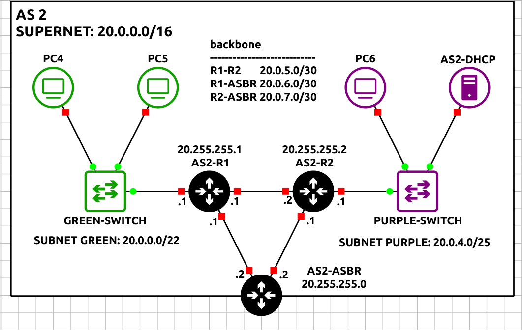
Figure 7 – AS2 network complete
- Class B Supernet – 20.0.0.0/16
Phase II – Configuring BGPv4 on MikroTik RouterOS
BGPv4, the routing protocol for connecting independent autonomous systems (AS), is used between border routers to relay any information necessary by each AS. It’s vital to understand that BGP is utilized by many ASNs because they may not all be part of the same entity, as well as to give administrators more control over how data is transferred between destinations.
- At this point, you should two small networks that resemble the following figure:
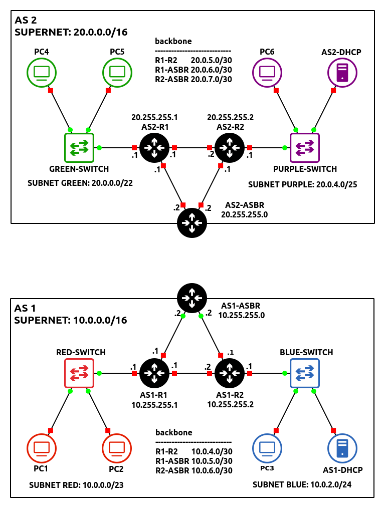
Figure 8 – Both networks in GNS3 - Connect two ASBR’s together using a random network of your choice
NOTE: In this example, ether1 of both border routers are connected over the 172.155.10.0/30 network. Don’t forget to update the interface IP addresses!
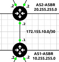
Figure 9 – Connecting AS1 and AS2 - Initialize a Wireshark packet capture between the two AS networks
- Create a new BGP instance on AS1-ASBR
> routing bgp connection add name=HOST-TO-AS2 as=1 local.role=ebgp router-id=10.255.255.0 remote.address=172.155.10.2 output.redistribute=connected,ospf
Command Definition name Name of the new connection instance. This can be anything, but it should represent its function for best practice. as ASN integer of the local autonomous system. local.role Specifies whether BGP is being used internally (ibgp) or externally (ebgp). Since we are connecting two different AS-es, eBGP is preferred. router-id The identification of the local router for the receiving router to recognize. remote.address Specifies the remote interface address of the receiving router. output.redistribute Specified which routes to be shared with any connected BGP neighbors - In Wireshark, you should now see TCP SYN packets attempting to establish a BGP session with AS2-ASBR
NOTE: You should NOT see any OSPF Hello packets on this link!!
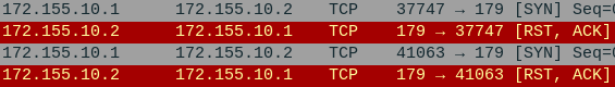
Figure 10 – Wireshark packet capture - Create a new BGP instance on AS2-ASBR
> routing bgp connection add name=HOST-TO-AS1 as=2 local.role=ebgp router-id=20.255.255.0 remote.address=172.155.10.1 output.redistribute=connected,ospf
- You will know when you are successful if you see the following packets in Wireshark
NOTE: Looking at Wireshark, you should notice a TCP handshake occur between the two routers followed by two OPEN messages and a steady stream of KEEPALIVE messages. This means that the connection was successful and both routers are able to communicate with each other. After every BGP packet, the recipient will respond with an obligatory TCP ACK segment, acknowledging a successful transmission of data.
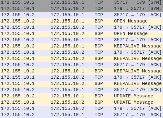
Figure 11 – Wireshark packet capture - You should also start to see UPDATE messages containing Network Layer Reachability Information (NLRI)
NOTE: Looking at the details of this packet will reveal the network addresses being distributed by BGP. In the example below, AS2-ASBR is telling AS2 about the nine subnets on its network.
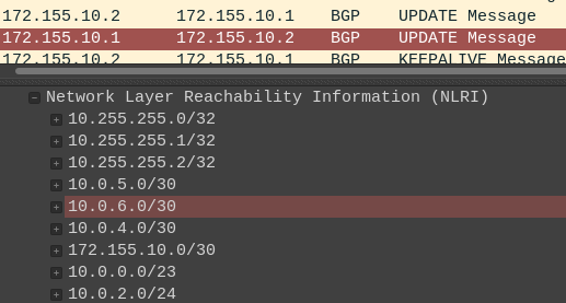
Figure 12 – BGP Update packet analysis
Phase III – Testing the BGP Connection
Now that we have a BGP session started, hopefully we have cross-network communication working.
- From PC1, trace the path to any device on the Green subnet
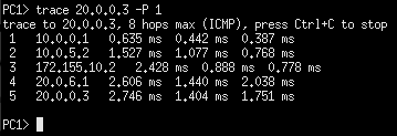
Figure 13 – PC1 tracing path to PC4 - Cut some links PC1 used to test the integrity of both networks
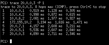
Figure 14 – PC1 re-tracing path to PC4
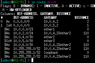
Congratulations! You made a small enterprise network that can dynamically update using various routing protocols. You may be asking yourself, whats the point of BGP? Couldn’t we have simply used OSPF to create the same results? Look at the routing table on AS1-R1:
Now compare this with the routing table on AS1-ASBR:
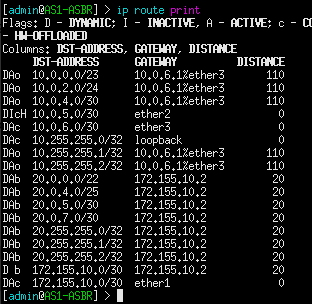
Notice how AS1-R1 only cares about the routes in its local AS, while the border router takes on the burden of inter-network communication. This is the power of BGP: to offload some networking tasks to dedicated machines, so that other routers can perform more efficiently in their given area.
BGP Troubleshooting
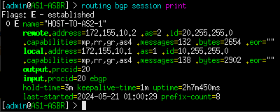
The following router commands are useful in troubleshooting errors you might encounter. Below is the expected output for AS1-ASBR.
1. View established sessions. In this example, there should only be one on both border routers. If there is no output, that means that the neighboring router failed to connect either due to faulty configuration or no configuration at all.
> routing bpg session print
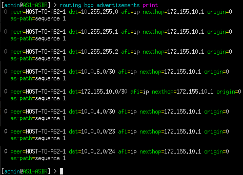
2. View routes currently being advertised to peers. Remember, we only want to advertise connected and OSPF routes. If a specific network is missing, verify that the problem router is configured properly. Check interface IP addresses and OSPF configuration.
> routing bgp advertisements print
3. View all routes currently known by the router.
> ip route print
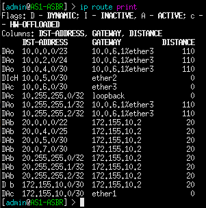
NOTE: Also be sure to verify that all internal routers are assigned default routes that point to their associated ASBR.
End of Lab
Deliverables
4 Screenshot are needed to earn credit for this exercise:
- Screenshot of GNS3 Workspace with all devices labeled
- Wireshark capture of the TCP and BGP packets being exchanged
- Wireshark view of the ‘keep alive’ messages
- Wireshark view of the “update” packets with the NLRI view
Homeworks
Assignment 1 – Eliminate the single point of failure. AS1 and AS2 are only connected by one network path. This is bad practice. Add another BGP router (AS3) and add it to the backbone.
- RECOMMENDED GRADING CRITERIA
- Screenshot of GNS3 Workspace with all devices labeled
- Wireshark capture of the TCP and BGP packets being exchanged with the new router
- Wireshark view of the ‘keep alive’ messages with the new router
- Wireshark view of the “update” packets with the NLRI view of the new router
Assignment 2 – The Red and Green Teams must relocate their services to a different building. Rebuild the Red and Green team network architecture, attaching them to AS3-ABSR, and disable the legacy connections. This move is temporary, so use the routers to generate DHCP for the users.
- RECOMMENDED GRADING CRITERIA
- Screenshot of GNS3 Workspace with all devices labeled
- Screenshot of a successful trace route from a Green PC to a Blue PC
- Screenshot of a successful trace route from a Green PC to a Gray PC
- Screenshot of AS3-ABSR routing table
Figure 00 – Contact us via prmaster@erau.edu
